Page 207 of 273
204 Tires, wheels
Te ch n ica l
data Instruments
and controlsOperation DrivingInstrument
cluster displayPractical hintsCar care Index
6.Holding the jack, unfold pin (1) and handle (2).
Insert pin fully into the tube hole up to the stop.
Crank handle clockwise until jack base (3) meets
the ground. Place jack on firm ground. Position the
jack so that it is always vertical (plump-line) as seen
from the side (see arrow), even if the vehicle is
parked on an incline.
7.Jack up the vehicle until the wheel is clear of the
ground. Never start engine while vehicle is raised.8.Unscrew upper-most wheel bolt and screw in
alignment pin (4) supplied in the tool kit. Remove
the remaining bolts. Keep bolt threads protected
from dirt and sand.
9. Remove wheel. Grip wheel from the sides. Keep
hands from beneath the wheels.
Page 210 of 273
207 Tires, wheels
Te ch n ica l
data Instruments
and controlsOperation DrivingInstrument
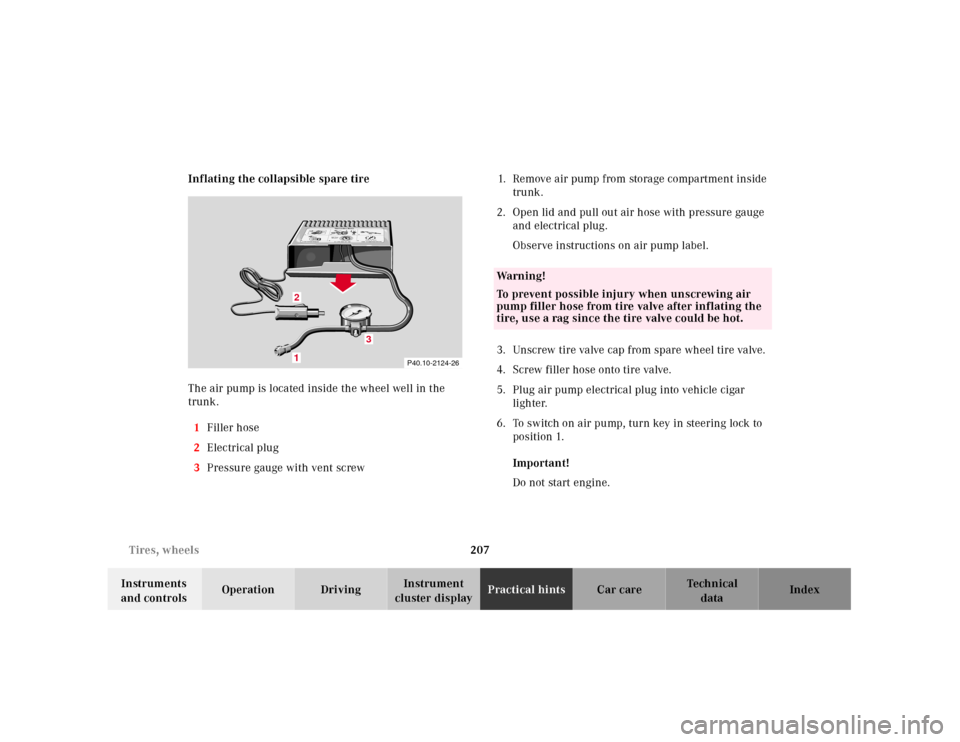
cluster displayPractical hintsCar care Index Inflating the collapsible spare tire
The air pump is located inside the wheel well in the
trunk.
1Filler hose
2Electrical plug
3Pressure gauge with vent screw1.Remove air pump from storage compartment inside
trunk.
2.Open lid and pull out air hose with pressure gauge
and electrical plug.
Observe instructions on air pump label.
3.Unscrew tire valve cap from spare wheel tire valve.
4.Screw filler hose onto tire valve.
5.Plug air pump electrical plug into vehicle cigar
lighter.
6.To switch on air pump, turn key in steering lock to
position 1.
Important!
Do not start engine.
P40.10-2124-26
1
0
45 6max. 6 min
A 170 584 01 38 AIR COMPRESSOR 23
Mercedes-Benz
2
3
2 1
1
2,5 bar
36 psi1
0 23
4
5
620PSI
BAR40
60
80
LUFTPRESSER12
12
3
Wa r n i n g !
To prevent possible injury when unscrewing air
pump filler hose from tire valve after inflating the
tire, use a rag since the tire valve could be hot.
Page 211 of 273
208 Tires, wheels
Te ch n ica l
data Instruments
and controlsOperation DrivingInstrument
cluster displayPractical hintsCar care Index
7.Operate air pump (approximately 5 minutes) until
pressure gauge displays 36 psi (2.5 bar).
8.To switch off air pump, turn key in steering lock to
position 0.
9.Unscrew filler hose from tire. Reinstall tire valve
cap.
Note:
Excessive tire air pressure should be released using the
vent screw.Storing spare wheel in wheel well
Deflate spare tire:
1.Unscrew valve stem removal tool, which is a part of
the valve cap, from tire valve.
2.Using the valve stem removal tool, open tire valve
slightly by turning the tire valve insert
counterclockwise to release air pressure.
3.When the tire air pressure has been released,
remove tire valve insert (protect it from dirt and
sand) using the previously removed tire valve cap.
4.Once all air is out of the tire, and the tire has
collapsed to its original shape, reinstall the tire
valve insert and valve cap.
Place spare wheel in wheel well and secure it with air
pump holder. Turn pump holder clockwise to its stop.
Page 214 of 273
211 Battery
Te ch n ica l
data Instruments
and controlsOperation DrivingInstrument
cluster displayPractical hintsCar care Index Therefore, we strongly recommend that you have the
battery charge checked frequently, and corrected if
necessary, especially if you use the vehicle less than
approximately 200 miles (300 km) per month,
mostly for short distance trips, or if it is not used for
long periods of time.
Only charge a battery with a battery charger after the
battery has been disconnected from the vehicle’s
electrical circuit.
Always disconnect the battery negative lead first and
connect last.
When removing and connecting the battery, always
make sure that all electrical consumers are off and the
key is in steering lock position 0. The battery must
always be securely installed when the vehicle is in
operation. During removal and installation always
protect the disconnected battery positive (+) terminal
with the cover attached to the battery.
While the engine is running the battery terminal clamps
must not be loosened or detached, otherwise the
generator and other electronic components will be
damaged.Battery recycling
Batteries contain materials that can harm the
environment with improper disposal.
Large 12 Volt storage batteries contain lead.
Recycling of batteries is the preferred method of
disposal.
Many states require sellers of batteries to accept old
batteries for recycling.
Page 218 of 273
215 Towing the vehicle
Te ch n ica l
data Instruments
and controlsOperation DrivingInstrument
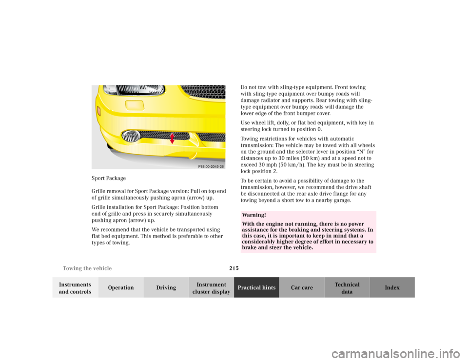
cluster displayPractical hintsCar care Index Sport Package
G r il l e re m ova l f or S p or t Pa cka g e v e rs i on : P u l l on t op e n d
of grille simultaneously pushing apron (arrow) up.
Grille installation for Sport Package: Position bottom
end of grille and press in securely simultaneously
pushing apron (arrow) up.
We recommend that the vehicle be transported using
f lat bed equipment. This method is preferable to other
types of towing.Do not tow with sling-type equipment. Front towing
with sling-type equipment over bumpy roads will
damage radiator and supports. Rear towing with sling-
type equipment over bumpy roads will damage the
lower edge of the front bumper cover.
Use wheel lift, dolly, or f lat bed equipment, with key in
steering lock turned to position 0.
Towing restrictions for vehicles with automatic
transmission: The vehicle may be towed with all wheels
on the ground and the selector lever in position “N” for
distances up to 30 miles (50 km) and at a speed not to
exceed 30 mph (50 km / h). The key must be in steering
lock position 2.
To be certain to avoid a possibility of damage to the
transmission, however, we recommend the drive shaft
be disconnected at the rear axle drive f lange for any
towing beyond a short tow to a nearby garage.
P88.00-2045-26
Wa r n i n g !
With the engine not running, there is no power
assistance for the braking and steering systems. In
this case, it is important to keep in mind that a
considerably higher degree of effort in necessary to
brake and steer the vehicle.
Page 219 of 273
216 Towing the vehicle
Te ch n ica l
data Instruments
and controlsOperation DrivingInstrument
cluster displayPractical hintsCar care Index
Important!
When towing the vehicle, please, note the following:
With the automatic central locking activated and the
key in steering lock position 2, the vehicle doors lock if
the left front wheel as well as the right rear wheel are
turning at vehicle speeds of approximately 9 mph
(15 km / h) or more.
To prevent the vehicle door locks from locking,
deactivate the automatic central locking.Note:
To signal turns while being towed with hazard warning
f lash er in u se, turn key in steering l ock to position 2 a nd
activate combination switch for left or right turn signal
in usual manner – only the selected turn signal will
operate. Upon canceling the turn signal, the hazard
warning flasher will operate again.
Caution!
If the vehicle is towed with the front axle raised, the
engine must be shut off (key in steering lock position 0
or 1). Otherwise, the ESP will immediately be engaged
and will apply the rear wheel brakes. Switch off the
tow-away alarm as well as the ESP, see page 37 and 170.
Page 220 of 273
217 Towing the vehicle
Te ch n ica l
data Instruments
and controlsOperation DrivingInstrument
cluster displayPractical hintsCar care Index Transmission selector lever, manually unlocking
In the case of power failure the transmission selector
lever can be manually unlocked, e.g. when towing the
vehicle.To do so, insert a pin (1), e.g. ball point pen, into the
covered opening below the position “D” of the shift
pattern. While pushing the pin down, move selector
lever from position “P”.
Af ter remova l of t he pin f rom th e opening , t he cover will
not close fully. Only after moving the selector lever to
positions “D+” and “D–” does the cover return to its
closed position.
P27.60-2101-26
1
Page 222 of 273
219 Exterior lamps
Te ch n ica l
data Instruments
and controlsOperation DrivingInstrument
cluster displayPractical hintsCar care Index Headlamp assembly
1Bulb socket for turn signal, parking and
standing lamp
2Headlamp cover with locking tab3Electrical connector for low beam headlamp bulb
4Electrical connector for high beam headlamp bulb
2
P82.10-2351-26
1
P82.10-2352-26
3
4