2001 MERCEDES-BENZ ML430 trip computer
[x] Cancel search: trip computerPage 4 of 317

1 Contents
IntroductionProduct information .......................... 7
Roadside assistance ......................... 10
Where to find it ................................ 14
Reporting Safety Defects ................ 16Instruments and controlsInstruments and controls ............... 18
Center console .............................. 20
Overhead control panel ............... 21OperationVehicle keys ...................................... 24
Start lock-out .................................... 25
General notes on the
central locking system ............... 26
Central locking system ................... 26
Radio frequency
remote control .............................. 26
Unlocking the liftgate .................. 28
Panic button .................................. 28
Mechanical keys ........................... 29Doors ................................................. 30
Central locking switch .................... 32
Automatic central locking .......... 32
Emergency unlocking in case
of accident ................................... 33
Liftgate .............................................. 34
Antitheft alarm system ................... 35
Tow-away alarm and
glass breakage sensor ............... 36
Seats, front ....................................... 37
Manual seats ................................ 39
Power seats ................................... 40
Head restraint ...............................41
Heated seats ..................................... 44
Seat belts and integrated
restraint system .......................... 46
Seat belts .......................................... 46
Seat belt nonusage
warning system ............................ 47
BabySmart
TM airbag
deactivation system ................... 53
Self-test BabySmart
TM
without special child
seat installed ................................ 53Supplemental restraint
system (SRS) ................................ 54
Emergency tensioning
retractor (ETR) ............................. 55
Airbags .............................................. 56
Safety guidelines for the
seat belt, emergency
tensioning retractor
and airbag ..................................... 63
Infant and child
restraint systems .......................... 65
Adjustable steering wheel .............. 70
Inside rear view mirror .................. 71
Antiglare night position .............. 71
Exterior rear view mirrors ............. 73
Exterior rear view mirror,
electrically folding ....................... 75
Instrument cluster ........................... 76
Indicator lamps in the
instrument cluster ...................... 78
Trip computer ................................... 83
Flexible service system (FSS) ........ 87
Engine oil level indicator ................ 89
Exterior lamp switch ....................... 90
Page 25 of 317

22 Contents - Operation
Te ch n ica l
data Instruments
and controlsOperationDrivingInstrument
cluster displayPractical hints Car care Index
OperationVehicle keys ...................................... 24
Start lock-out .................................... 25
General notes on the
central locking system ............... 26
Central locking system ................... 26
Radio frequency
remote control .............................. 26
Unlocking the liftgate .................. 28
Panic button .................................. 28
Mechanical keys ........................... 29
Doors .................................................. 30
Central locking switch .................... 32
Automatic central locking .......... 32
Emergency unlocking in case
of accident .................................... 33
Liftgate ............................................... 34
Antitheft alarm system ................... 35
Tow - aw ay a lar m a n d
glass breakage sensor ................ 36
Seats, front ........................................ 37
Manual seats ................................. 39
Power seats ................................... 40Head restraint ...............................41
Heated seats ..................................... 44
Seat belts and integrated
restraint system .......................... 46
Seat belts .......................................... 46
Seat belt nonusage
warning system ............................ 47
BabySmart
TM airbag
deactivation system ................... 53
Self-test BabySmart
TM
without special child
seat installed ................................ 53
Supplemental restraint
system (SRS) ............................... 54
Emergency tensioning
retractor (ETR) ............................ 55
Airbags .............................................. 56
Safety guidelines for the
seat belt, emergency
tensioning retractor
and airbag ..................................... 63
Infant and child
restraint systems ......................... 65
Adjustable steering wheel .............. 70
Inside rear view mirror ...................71Antiglare night position .............. 71
Exterior rear view mirrors ............. 73
Exterior rear view mirror,
electrically folding ....................... 75
Instrument cluster ........................... 76
Indicator lamps in the
instrument cluster ...................... 78
Trip computer ................................... 83
Flexible service system (FSS) ........ 87
Engine oil level indicator ................ 89
Exterior lamp switch ....................... 90
Fo g la mp sw itch
(except Canada) .......................... 92
Fo g la mp sw itch
(Canada only) .............................. 93
Hazard warning flasher
switch ............................................ 94
Headlamp cleaning system ............ 94
Windshield wiper/washer
switch ............................................ 95
Rear window wiper/washer ........... 96
Climate control ................................. 98
Basic setting – Heater ............... 100
Page 39 of 317

36 Tow-away protection
Te ch n ica l
data Instruments
and controlsOperationDrivingInstrument
cluster displayPractical hints Car care Index
Tow-away alarm and glass breakage sensor
The switch is located in the overhead console.
The tow-away alarm and glass breakage sensor are part
of the antitheft alarm system.
Once the alarm system has been armed, the turn signal
lamps will flash rapidly and the horn will sound when
someone attempts to raise the vehicle, or breaks a
window and reaches into the passenger compartment.The alarm will last approximately 3 minutes in the form
of rapidly flashing turn signal lamps. At the same time
the horn will sound for approximately 30 seconds. The
alarm will stay on even if the vehicle is immediately
lowered.
If the alarm stays on for more than 20 seconds, an
emergency call is initiated automatically. See Tele Aid
on page 148.
To prevent triggering the tow-away alarm feature, switch
off the tow-away alarm and glass breakage sensor before
towing the vehicle, or when parking on a surface subject
to movement, such as a ferry or auto train.
To do so, turn key in steering lock to position 1, then
return it to position 0 and remove key from steering
lock.
Within 30 seconds, push left or right button. (On
vehicles equipped with optional trip computer, push
RESET or MODE button, display shows OFF.)
Exit vehicle, and lock vehicle with remote control.
The tow-away alarm and glass breakage sensor remain
switched off until the key is inserted in steering lock
and turned to position 1.
Page 86 of 317
83 Trip computer
Te ch n ica l
data Instruments
and controlsOperationDrivingInstrument
cluster displayPractical hints Car care Index Trip computer (standard; optional on model ML 320)
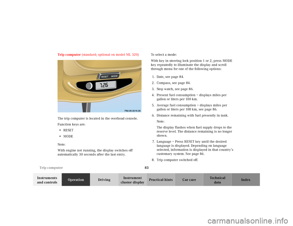
The trip computer is located in the overhead console.
Function keys are:
•RESET
•MODE
Note:
With engine not running, the display switches off
automatically 30 seconds after the last entry.To select a mode:
With key in steering lock position 1 or 2, press MODE
key repeatedly to illuminate the display and scroll
through menu for one of the following options:
1. Date, see page 84.
2. Compass, see page 84.
3. Stop watch, see page 86.
4. Present fuel consumption – displays miles per
gallon or liters pe r 100 km.
5. Average fuel consumption – displays miles per
gallon or liters per 100 km, see page 86.
6. Distance remaining with fuel presently in tank.
Note:
The display f lashes when fuel supply drops to the
reserve level. The distance remaining is no longer
shown.
7. Language – Press RESET key until the desired
language is displayed. Depending on language
selected, information is displayed in that country’s
customary system. See page 86.
8. Trip computer switched off.
MODE
Page 87 of 317
84 Trip computer
Te ch n ica l
data Instruments
and controlsOperationDrivingInstrument
cluster displayPractical hints Car care Index
To change an entry, select mode to be changed:
•Date –
Press RESET key, the month shown blinks. Now
press MODE key to advance to selected month.
Press RESET key again, the day shown blinks. Now
press MODE key to advance to selected day.
Press RESET key again, the year shown blinks. Now
press MODE key to advance to selected year.
Press RESET key again, the display stops blinking
and the date is set.
•Compass –
The compass displays the direction the vehicle is
traveling, such as N, NE, E, SE, S, SW, W or NW.
Note:
The presence of buildings, bridges, power lines and
large antenna masts can influence the displayed
values. Metallic or magnetic objects in or on the
vehicle can influence the accuracy of the compass.To change the compass zones:
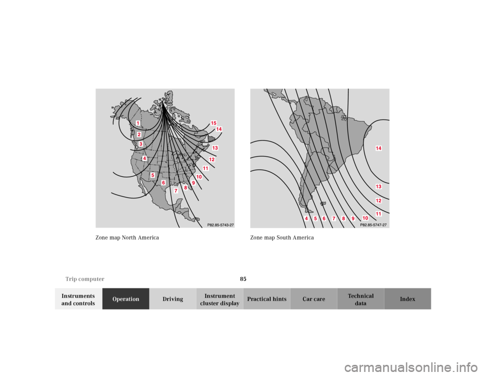
Determine the geographical point of the vehicle with the
aid of the zone maps below:
1. Turn key in steering lock to position 2.
2. Press MODE key repeatedly until the compass
display appears in the trip computer display.
3. Press RESET key to select the compass zone mode.
The zone selected last is shown in the display.
4. Press RESET key repeatedly until the correct
compass zone, as determined from the zone map, is
shown in the display.
5. Press MODE key twice to activate the new compass
zone and change back to compass display.
Page 88 of 317
85 Trip computer
Te ch n ica l
data Instruments
and controlsOperationDrivingInstrument
cluster displayPractical hints Car care Index Zone map North America Zone map South America
Page 89 of 317
86 Trip computer
Te ch n ica l
data Instruments
and controlsOperationDrivingInstrument
cluster displayPractical hints Car care Index
To calibrate the compass:
If the vehicle was exposed to a significant magnetic
zone, such as high voltage power lines, the compass
may have to be calibrated.
Calibration of the compass should be done in an area
free of steel superstructures and power lines. All
electrical consumers (e.g. exterior lamps, climate
control, etc.) should be switched off, doors and liftgate
closed. Do not open or close the roof. An open door or
liftgate triggers the display “–––”.
1. Start and run the engine.
2. Press MODE key repeatedly until the compass
display appears in the trip computer display.
3. Press RESET key to select the compass zone display.
4. Press RESET repeatedly until the correct zone, as
determined from the zone map (see page 85), is
shown in the display.
5. Press MODE key, “CAL–” appears in the display.
6. Press and hold RESET for a minimum of 2 seconds.7. Without interruption drive two or more full circles
at a speed between 3 mph (5 km / h) and 7 mph
(10 km / h) during which the message “CAL” is
replaced with a compass bearing (e.g. N, SW etc.),
immediately followed by three full circles at the
same speed, with only the rear window defroster
switched on. The defroster can be switched off
again. The calibration of the compass is now
complete.
•Stop watch –
Press RESET key to start the count. Press again to
stop the count. Press and hold RESET key to reset
sto p watch.
•Average fuel consumption –
Press RESET key to delete present reading.
•Language –
Press RESET key to set the language used in the
display.
Page 255 of 317
252 Battery
Te ch n ica l
data Instruments
and controlsOperation DrivingInstrument
cluster displayPractical hintsCar care Index
Therefore, we strongly recommend that you have the
battery charge checked frequently, and corrected if
necessary, especially if you use the vehicle less than
approximately 200 miles (300 km) per month,
mostly for short distance trips, or if it is not used for
long periods of time.
Only charge a battery with a battery charger after the
battery has been disconnected from the vehicle’s
electrical circuit.
Always disconnect the battery negative lead first and
connect last.
When removing and connecting the battery, always
make sure that all electrical consumers are off and the
key is in steering lock position 0. The battery must
always be securely installed when the vehicle is in
operation. During removal and installation always
protect the disconnected battery positive (+) terminal
with the cover attached to the battery.
While the engine is running the battery terminal clamps
must not be loosened or detached, otherwise the
generator and other electronic components would be
damaged.Note:
After reconnecting the battery also set the clock in
instrument cluster (see page 80), set date in trip
computer (see page 83), resynchronize the sliding / pop-
up roof (see page 272), the Skyview Top (see page 273)
and the electronic stability program (ESP) (see
page 206).
Battery recycling
Batteries contain material that can harm the
environment with improper disposal.
Large 12 Volt storage batteries contain lead.
Recycling of batteries is the preferred method of
disposal.
Many states require sellers of batteries to accept old
batteries for recycling.