2001 MERCEDES-BENZ ML320 Overhead
[x] Cancel search: OverheadPage 4 of 317

1 Contents
IntroductionProduct information .......................... 7
Roadside assistance ......................... 10
Where to find it ................................ 14
Reporting Safety Defects ................ 16Instruments and controlsInstruments and controls ............... 18
Center console .............................. 20
Overhead control panel ............... 21OperationVehicle keys ...................................... 24
Start lock-out .................................... 25
General notes on the
central locking system ............... 26
Central locking system ................... 26
Radio frequency
remote control .............................. 26
Unlocking the liftgate .................. 28
Panic button .................................. 28
Mechanical keys ........................... 29Doors ................................................. 30
Central locking switch .................... 32
Automatic central locking .......... 32
Emergency unlocking in case
of accident ................................... 33
Liftgate .............................................. 34
Antitheft alarm system ................... 35
Tow-away alarm and
glass breakage sensor ............... 36
Seats, front ....................................... 37
Manual seats ................................ 39
Power seats ................................... 40
Head restraint ...............................41
Heated seats ..................................... 44
Seat belts and integrated
restraint system .......................... 46
Seat belts .......................................... 46
Seat belt nonusage
warning system ............................ 47
BabySmart
TM airbag
deactivation system ................... 53
Self-test BabySmart
TM
without special child
seat installed ................................ 53Supplemental restraint
system (SRS) ................................ 54
Emergency tensioning
retractor (ETR) ............................. 55
Airbags .............................................. 56
Safety guidelines for the
seat belt, emergency
tensioning retractor
and airbag ..................................... 63
Infant and child
restraint systems .......................... 65
Adjustable steering wheel .............. 70
Inside rear view mirror .................. 71
Antiglare night position .............. 71
Exterior rear view mirrors ............. 73
Exterior rear view mirror,
electrically folding ....................... 75
Instrument cluster ........................... 76
Indicator lamps in the
instrument cluster ...................... 78
Trip computer ................................... 83
Flexible service system (FSS) ........ 87
Engine oil level indicator ................ 89
Exterior lamp switch ....................... 90
Page 20 of 317
17 Contents - Instruments and controls
Te ch n ica l
data Instruments
and controlsOperation DrivingInstrument
cluster displayPractical hints Car care Index
Instruments and controlsInstruments and controls ............... 18
Center console .............................. 20
Overhead control panel ............... 21
Page 24 of 317
21 Instruments and controls
Te ch n ica l
data Instruments
and controlsOperation DrivingInstrument
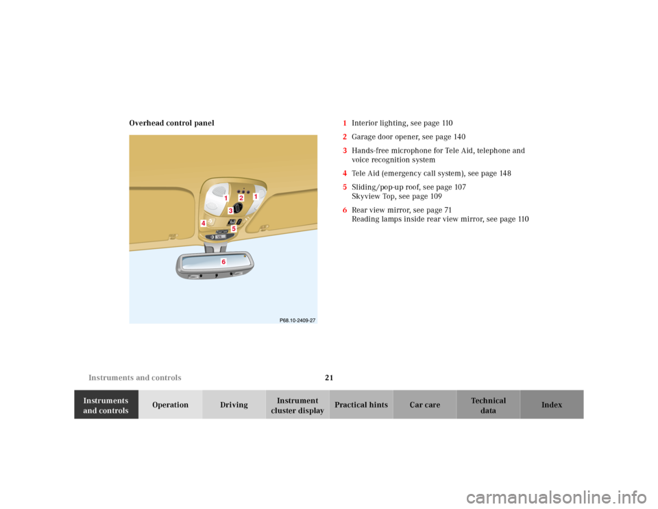
cluster displayPractical hints Car care Index Overhead control panel1Interior lighting, see page 110
2Garage door opener, see page 140
3Hands-free microphone for Tele Aid, telephone and
voice recognition system
4Tele Aid (emergency call system), see page 148
5Sliding /pop-up roof, see page 107
Skyview Top, see page 109
6Rear view mirror, see page 71
Reading lamps inside rear view mirror, see page 110
1
2
3
4
5
6
1
Page 39 of 317

36 Tow-away protection
Te ch n ica l
data Instruments
and controlsOperationDrivingInstrument
cluster displayPractical hints Car care Index
Tow-away alarm and glass breakage sensor
The switch is located in the overhead console.
The tow-away alarm and glass breakage sensor are part
of the antitheft alarm system.
Once the alarm system has been armed, the turn signal
lamps will flash rapidly and the horn will sound when
someone attempts to raise the vehicle, or breaks a
window and reaches into the passenger compartment.The alarm will last approximately 3 minutes in the form
of rapidly flashing turn signal lamps. At the same time
the horn will sound for approximately 30 seconds. The
alarm will stay on even if the vehicle is immediately
lowered.
If the alarm stays on for more than 20 seconds, an
emergency call is initiated automatically. See Tele Aid
on page 148.
To prevent triggering the tow-away alarm feature, switch
off the tow-away alarm and glass breakage sensor before
towing the vehicle, or when parking on a surface subject
to movement, such as a ferry or auto train.
To do so, turn key in steering lock to position 1, then
return it to position 0 and remove key from steering
lock.
Within 30 seconds, push left or right button. (On
vehicles equipped with optional trip computer, push
RESET or MODE button, display shows OFF.)
Exit vehicle, and lock vehicle with remote control.
The tow-away alarm and glass breakage sensor remain
switched off until the key is inserted in steering lock
and turned to position 1.
Page 86 of 317
83 Trip computer
Te ch n ica l
data Instruments
and controlsOperationDrivingInstrument
cluster displayPractical hints Car care Index Trip computer (standard; optional on model ML 320)
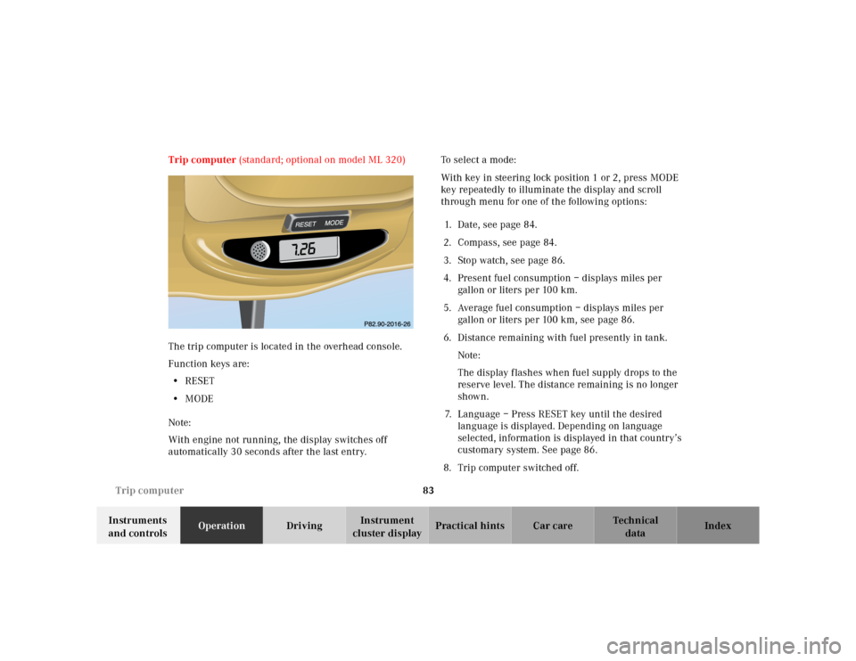
The trip computer is located in the overhead console.
Function keys are:
•RESET
•MODE
Note:
With engine not running, the display switches off
automatically 30 seconds after the last entry.To select a mode:
With key in steering lock position 1 or 2, press MODE
key repeatedly to illuminate the display and scroll
through menu for one of the following options:
1. Date, see page 84.
2. Compass, see page 84.
3. Stop watch, see page 86.
4. Present fuel consumption – displays miles per
gallon or liters pe r 100 km.
5. Average fuel consumption – displays miles per
gallon or liters per 100 km, see page 86.
6. Distance remaining with fuel presently in tank.
Note:
The display f lashes when fuel supply drops to the
reserve level. The distance remaining is no longer
shown.
7. Language – Press RESET key until the desired
language is displayed. Depending on language
selected, information is displayed in that country’s
customary system. See page 86.
8. Trip computer switched off.
MODE
Page 144 of 317
141 Garage door opener
Te ch n ica l
data Instruments
and controlsOperationDrivingInstrument
cluster displayPractical hints Car care Index For operation in the USA only: This device complies
with Part 15, Subpart C, Section 209 of the FCC Rules.
Operation is subject to the following two conditions:
(1) This device may not cause harmful interference, and
(2) this device must accept any interference received,
including interference that may cause undesired
operation.
WARNING: Changes or modification not expressly
approved by party responsible for compliance could void
the user’s authority to operate the equipment.
Programming or reprogramming the integrated
remote control:
1. Turn key in steering lock to position 1 or 2.
2. Hold the end of the hand-held transmitter of the
device you wish to train approximately 2 to 5 inches
(5 cm to 12 cm) away from the surface of the
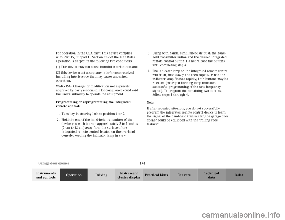
integrated remote control located on the overhead
console, keeping the indicator lamp in view.3. Using both hands, simultaneously push the hand-
held transmitter button and the desired integrated
remote control button. Do not release the buttons
until completing step 4.
4. The indicator lamp on the integrated remote control
will flash, first slowly and then rapidly. When the
indicator lamp flashes rapidly, both buttons may be
released (the rapid flashing lamp indicates
successful programming of the new frequency
signal). To program the remaining two buttons,
follow ste ps 1 through 4.
Note:
If after repeated attempts, you do not successfully
program the integrated remote control device to learn
the signal of the hand-held transmitter, the garage door
opener could be equipped with the “rolling code
feature”.
Page 155 of 317
152 Tele Aid
Te ch n ica l
data Instruments
and controlsOperationDrivingInstrument
cluster displayPractical hints Car care Index
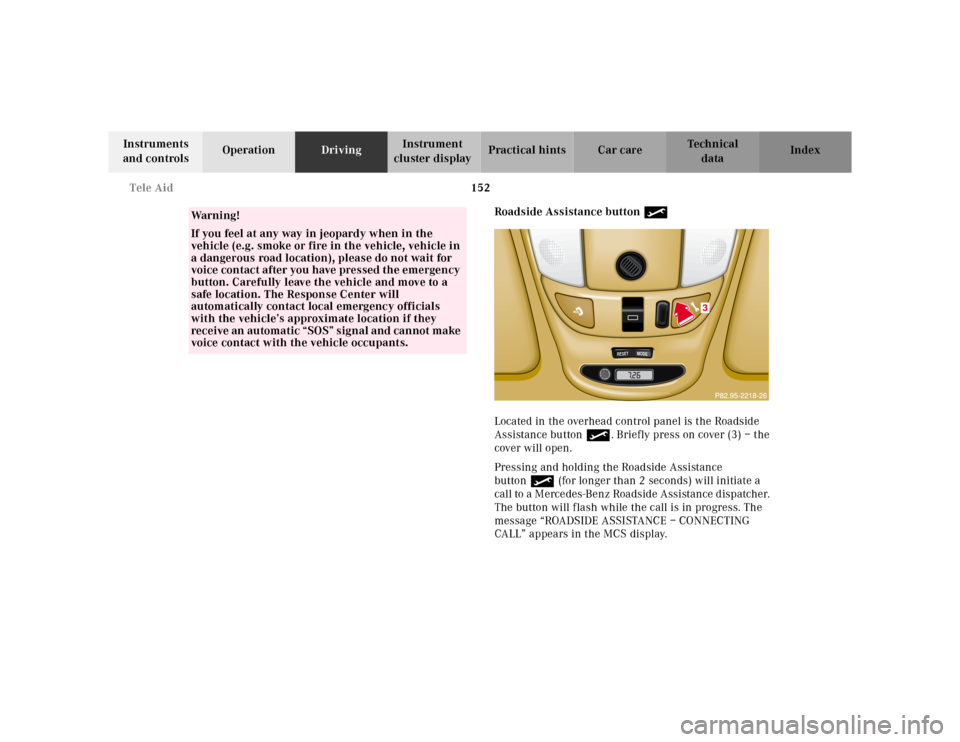
Roadside Assistance button •
Located in the overhead control panel is the Roadside
Assistance button•. Briefly press on cover (3) – the
cover will open.
Pressing and holding the Roadside Assistance
button• (for longer than 2 seconds) will initiate a
call to a Mercedes-Benz Roadside Assistance dispatcher.
The button will flash while the call is in progress. The
message “ROADSIDE ASSISTANCE – CONNECTING
CALL” appears in the MCS display.
Wa r n i n g !
If you feel at any way in jeopardy when in the
vehicle (e.g. smoke or fire in the vehicle, vehicle in
a dangerous road location), please do not wait for
voice contact after you have pressed the emergency
button. Carefully leave the vehicle and move to a
safe location. The Response Center will
automatically contact local emergency officials
with the vehicle’s approximate location if they
receive an automatic “SOS” signal and cannot make
voice contact with the vehicle occupants.
�����������������������������������������������������������������������������������������������������
RESET
MODE
3
Page 157 of 317
154 Tele Aid
Te ch n ica l
data Instruments
and controlsOperationDrivingInstrument
cluster displayPractical hints Car care Index
If the indicator lamp in the Roadside Assistance
button• is illuminated continuously and there was
no voice connection to the Response Center established,
then the Tele Aid system could not initiate an Roadside
Assistance call (e.g. the relevant cellular phone network
is not available). The message “ROADSIDE
ASSISTANCE – CALL FAILED” appears in the MCS
display.
Should this occur, assistance must be summoned by
other means.
Roadside Assistance calls can be terminated using the
END button on the MCS unit.Information button ¡
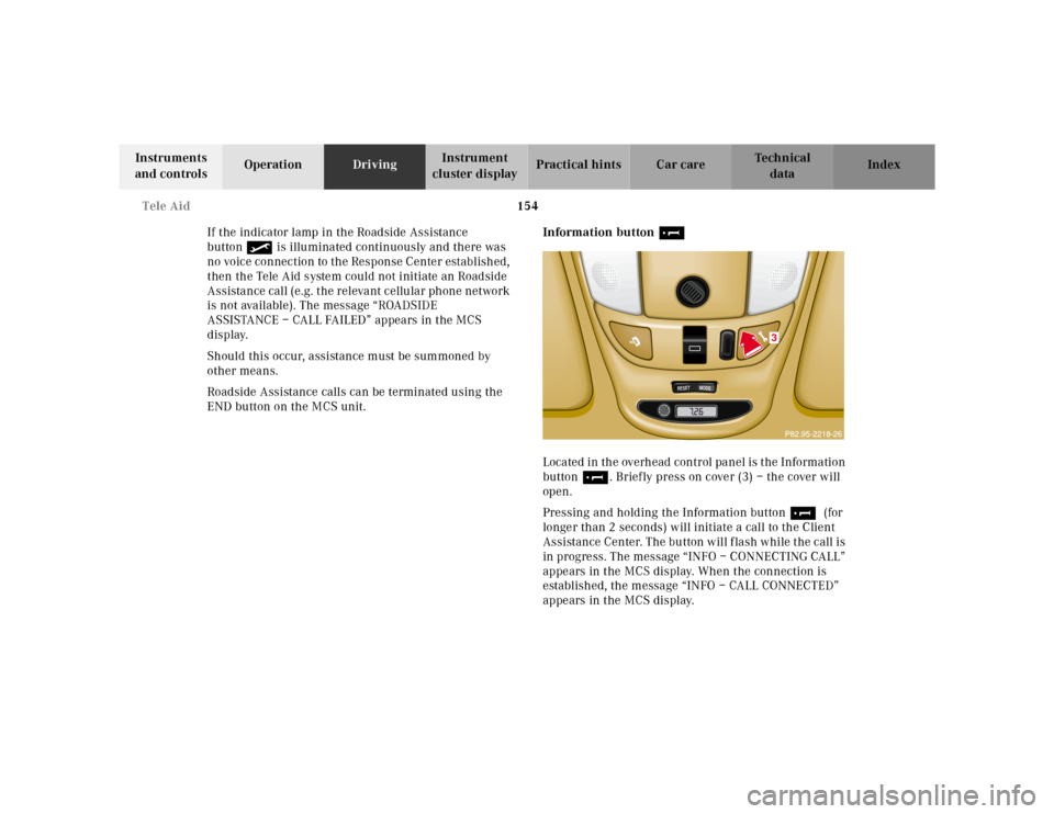
Located in the overhead control panel is the Information
button¡. Briefly press on cover (3) – the cover will
open.
Pressing and holding the Information button¡ (for
longer than 2 seconds) will initiate a call to the Client
Assistance Center. The button will flash while the call is
in progress. The message “INFO – CONNECTING CALL”
appears in the MCS display. When the connection is
established, the message “INFO – CALL CONNECTED”
appears in the MCS display.
�����������������������������������������������������������������������������������������������������
RESET
MODE
3