Page 251 of 317
248 Tires, Wheels
Te ch n ica l
data Instruments
and controlsOperation DrivingInstrument
cluster displayPractical hintsCar care Index
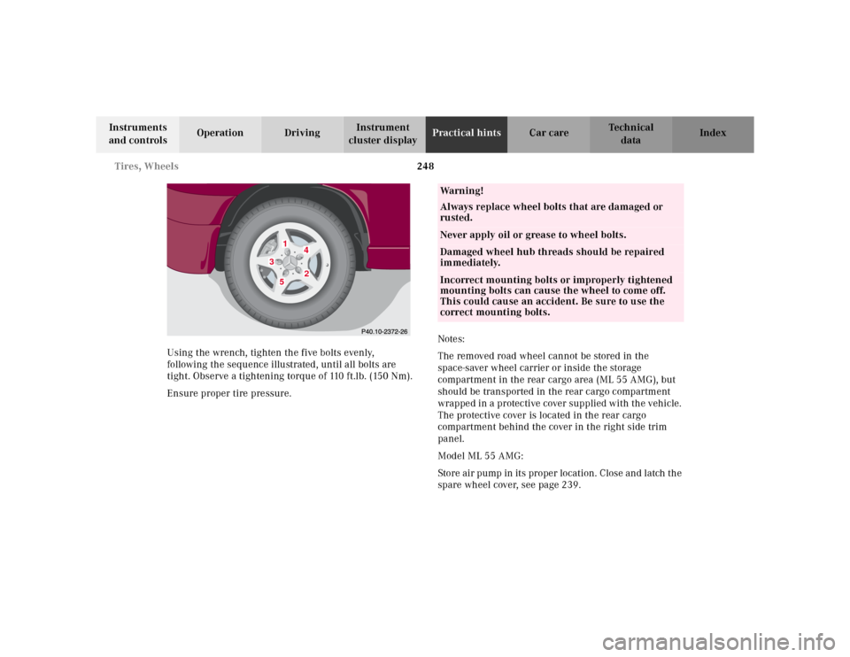
Using the wrench, tighten the five bolts evenly,
following the sequence illustrated, until all bolts are
tight. Observe a tightening torque of 110 ft.lb. (150 Nm).
Ensure proper tire pressure.Notes:
The removed road wheel cannot be stored in the
space-saver wheel carrier or inside the storage
compartment in the rear cargo area (ML 55 AMG), but
should be transported in the rear cargo compartment
wrapped in a protective cover supplied with the vehicle.
The protective cover is located in the rear cargo
compartment behind the cover in the right side trim
panel.
Model ML 55 AMG:
Store air pump in its proper location. Close and latch the
spare wheel cover, see page 239.
1
2
3
4
5
Wa r n i n g !
Always replace wheel bolts that are damaged or
rusted.Never apply oil or grease to wheel bolts.Damaged wheel hub threads should be repaired
immediately.Incorrect mounting bolts or improperly tightened
mounting bolts can cause the wheel to come off.
This could cause an accident. Be sure to use the
correct mounting bolts.
Page 252 of 317
249 Tires, Wheels
Te ch n ica l
data Instruments
and controlsOperation DrivingInstrument
cluster displayPractical hintsCar care Index Inflating the space-saver tire (ML 55 AMG only)
1. Remove air pump from compartment behind the
space-saver spare wheel.
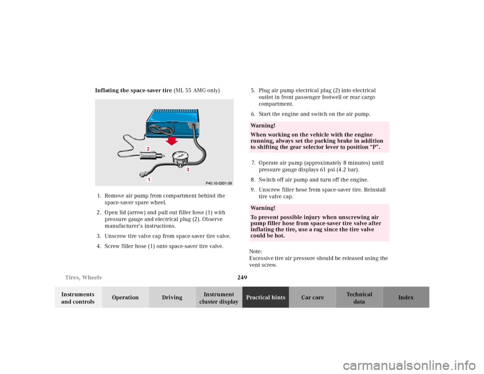
2. Open lid (arrow) and pull out filler hose (1) with
pressure gauge and electrical plug (2). Observe
manufacturer’s instructions.
3. Unscrew tire valve cap from space-saver tire valve.
4. Screw filler hose (1) onto space-saver tire valve.5. Plug air pump electrical plug (2) into electrical
outlet in front passenger footwell or rear cargo
compartment.
6. Start the engine and switch on the air pump.
7. Operate air pump (approximately 8 minutes) until
pressure gauge displays 61 psi (4.2 bar).
8. Switch off air pump and turn off the engine.
9. Unscrew filler hose from space-saver tire. Reinstall
tire valve cap.
Note:
Excessive tire air pressure should be released using the
vent screw.
3
12
Wa r n i n g !
When working on the vehicle with the engine
running, always set the parking brake in addition
to shifting the gear selector lever to position “P”.Wa r n i n g !
To prevent possible injury when unscrewing air
pump filler hose from space-saver tire valve after
inflating the tire, use a rag since the tire valve
could be hot.
Page 253 of 317
250 Tires, Wheels
Te ch n ica l
data Instruments
and controlsOperation DrivingInstrument
cluster displayPractical hintsCar care Index
Tire inflation pressure
A table (see fuel filler flap) lists the tire inflation
pressures specified for Mercedes-Benz recommended
tires as well as for the varying operating conditions.
Important!
Tire pressure changes by approximately 1.5 psi (0.1 bar)
per 18°F (10°C) of air temperature change. Keep this in
mind when checking tire pressure inside a garage –
especially in the winter.
Example:
If garage temperature = approximately +68°F (+20°C)
and ambient temperature = approximately +32°F (0°C)
then the adjusted air pressure = specified air pressure
+3 psi (+0.2 bar).Tire pressures listed for light loads are minimum values
offering high driving comfort. Increased inflation
pressures for heavy loads produce favorable handling
characteristics with lighter loads and are perfectly
permissible. The ride of the vehicle, however, will
become somewhat harder.
Tire temperature and pressure increase with the vehicle
speed. Tire pressure should therefore only be checked
and corrected on cold tires. Correct tire pressure in
warm tires only if pressure has dropped below the
pressure listed in the table and the respective operating
conditions are taken into consideration.
An underinf lated tire due to a slow leak (e.g. due to a
nail in the tire) may cause damage such as tread
separation, bulging etc.. Regular tire pressure checks
(including the spare tire) at intervals of no more than
14 days are therefore essential.
Page 258 of 317
255 Towing
Te ch n ica l
data Instruments
and controlsOperation DrivingInstrument
cluster displayPractical hintsCar care Index Tow in g t h e ve hic l e
Important!
When towing the vehicle, please, note the following:
With the automatic central locking activated and the
engine running, the vehicle doors lock if the left front
wheel is turning at vehicle speeds of approximately
9 mph (15 km / h) or more.
To prevent the vehicle door locks from locking,
deactivate the automatic central locking, see page 32.The front towing eye is located on the passenger side
below the bumper.
1To w i n g eye , f r o n t
Prior to towing the vehicle with all wheels on the
ground, make certain that the key is in steering
lock position 2.
P88.20-2160-26
Page 260 of 317
257 Towing
Te ch n ica l
data Instruments
and controlsOperation DrivingInstrument
cluster displayPractical hintsCar care Index ML 55 AMG
The rear towing eye is located behind the right side
cover (1) in the bumper panel.
3Cover
4Towing eye, rearCover removal:
Grip cover at bottom and pull out.
Cover installation:
Engage cover and press in securely.
We recommend that the vehicle be transported using
flat bed equipment. This method is preferable to other
types of towing.
The vehicle may be towed with all wheels on the ground
and the selector lever in position “N” for distances up to
30 miles (50 km) and at a speed not to exceed 30 mph
(50 k m / h). The key mu st be in stee ring lo ck p o sitio n 2.
Wa r n i n g !
In order to avoid possible serious burns or injury,
use extreme caution when removing the cover,
because the rear exhaust pipe is extremely hot.
Page 261 of 317
258 Towing
Te ch n ica l
data Instruments
and controlsOperation DrivingInstrument
cluster displayPractical hintsCar care Index
To be certain to avoid additional damage to the vehicle
powertrain, however you should d o the following:
•With damage to front axle, raise front axle. Remove
flexible drive shaft between rear axle and transfer
case
•With damage to rear axle, raise rear axle and tow
vehicle with wheel lift or dolly placed under front
wheels.
•With damage to transfer case, remove flexible drive
shafts to the drive axles.
Note:
Always install new self-locking nuts when reinstalling
the flexible drive shaft.Caution!
If the vehicle is towed with the front axle raised, the
engine must be shut off (key in steering lock position 1).
Otherwise, the 4-ETS+ may become engaged which may
cause loss of towing control. Switch off the tow-away
alarm (see page 36) as well as the ESP (see page 207).
Note:
To signal turns while being towed with hazard warning
flasher in use, turn key in steering lock to position 2
and activate combination switch for left or right turn
signal in usual manner. Now deactivate the hazard
warning flasher, only the selected turn signal will
operate. Upon canceling the turn signal, the hazard
warning flasher must be activated again.
Wa r n i n g !
With the engine not running, there is no power
assistance for the braking and steering systems. In
this case, it is important to keep in mind that a
considerably higher degree of effort is necessary to
brake and steer the vehicle.
Page 262 of 317
259 Towing
Te ch n ica l
data Instruments
and controlsOperation DrivingInstrument
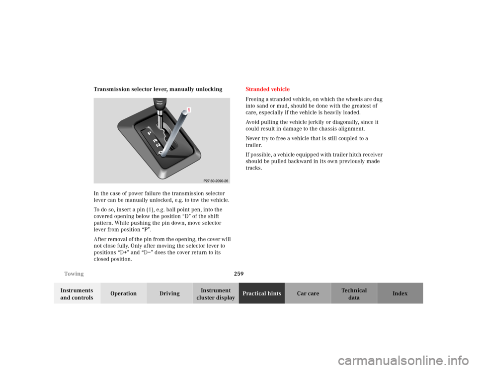
cluster displayPractical hintsCar care Index Transmission selector lever, manually unlocking
In the case of power failure the transmission selector
lever can be manually unlocked, e.g. to tow the vehicle.
To do so, insert a pin (1), e.g. ball point pen, into the
covered opening below the position “D” of the shift
pattern. While pushing the pin down, move selector
lever from position “P”.
After removal of the pin from the opening, the cover will
not close fully. Only after moving the selector lever to
positions “D+” and “D–” does the cover return to its
closed position.Stranded vehicle
Freeing a stranded vehicle, on which the wheels are dug
into sand or mud, should be done with the greatest of
care, especially if the vehicle is heavily loaded.
Avoid pulling the vehicle jerkily or diagonally, since it
could result in damage to the chassis alignment.
Never try to free a vehicle that is still coupled to a
trailer.
If possible, a vehicle equipped with trailer hitch receiver
should be pulled backward in its own previously made
tracks.
Page 280 of 317
277 Contents - Vehicle care
Te ch n ica l
data Instruments
and controlsOperation DrivingInstrument
cluster displayPractical hintsCar careIndex
Vehicle careCleaning and care
of the vehicle .............................278
Power washer ..............................279
Tar stains .....................................279
Paintwork, painted body
components .................................279
Engine cleaning ..........................280
Vehicle washing .........................280
Ornamental moldings ................280
Headlamps, taillamps,
turn signal lenses ......................280Window cleaning ....................... 281
Wiper blades .............................. 281
Light alloy wheels ..................... 281
Instrument cluster ..................... 281
Steering wheel and
gear selector lever ..................... 281
Cup holder .................................. 282
Seat belts ..................................... 282
Headliner .................................... 282
Upholstery .................................. 282
Hard plastic trim items ............. 282
Plastic and rubber parts ........... 282