2001 MERCEDES-BENZ CLK55AMG light
[x] Cancel search: lightPage 157 of 329
154 Interior equipment
Te ch n ica l
data Instruments
and controlsOperationDrivingInstrument
cluster displayPractical hints Car care Index
Glove box
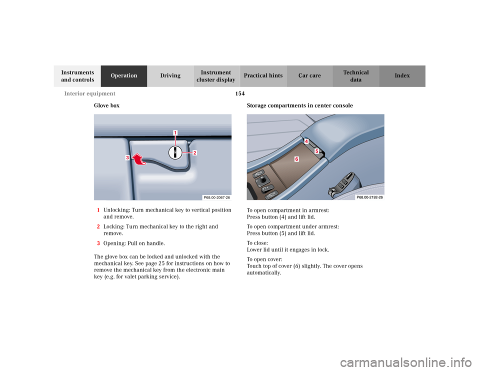
1Unlocking: Turn mechanical key to vertical position
and remove.
2Locking: Turn me chanical key to the right and
remove.
3Opening: Pull on handle.
The glove box can be locked and unlocked with the
mechanical key. See page 25 for instructions on how to
remove the mechanical key from the electronic main
key (e.g. for valet parking service).Storage compartments in center console
To open compartment in armrest:
Press button (4) and lift lid.
To open compartment under armrest:
Press button (5) and lift lid.
To c l o s e :
Lower lid until it engages in lock.
To o p e n c o ve r :
Touch top of cover (6) slightly. The cover opens
automatically.
P68.00-2067-26
3
1
2
Page 160 of 329
157 Interior equipment
Te ch n ica l
data Instruments
and controlsOperationDrivingInstrument
cluster displayPractical hints Car care Index Ashtrays
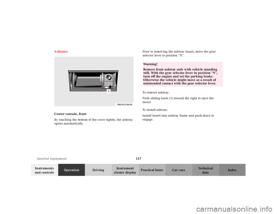
Center console, front
By touching the bottom of the cover lightly, the ashtray
opens automatically.Prior to removing the ashtray insert, move the gear
selector lever to position “N”.
To remove ashtray:
Push sliding knob (1) toward the right to eject the
insert.
To install ashtray:
Install insert into ashtray frame and push down to
engage.
Wa r n i n g !
Remove front ashtray only with vehicle standing
still. With the gear selector lever in position “N”,
turn off the engine and set the parking brake.
Otherwise the vehicle might move as a result of
unintended contact with the gear selector lever.
Page 162 of 329
159 Interior equipment
Te ch n ica l
data Instruments
and controlsOperationDrivingInstrument
cluster displayPractical hints Car care Index LighterTurn electronic key in steering lock to position 1 or 2.
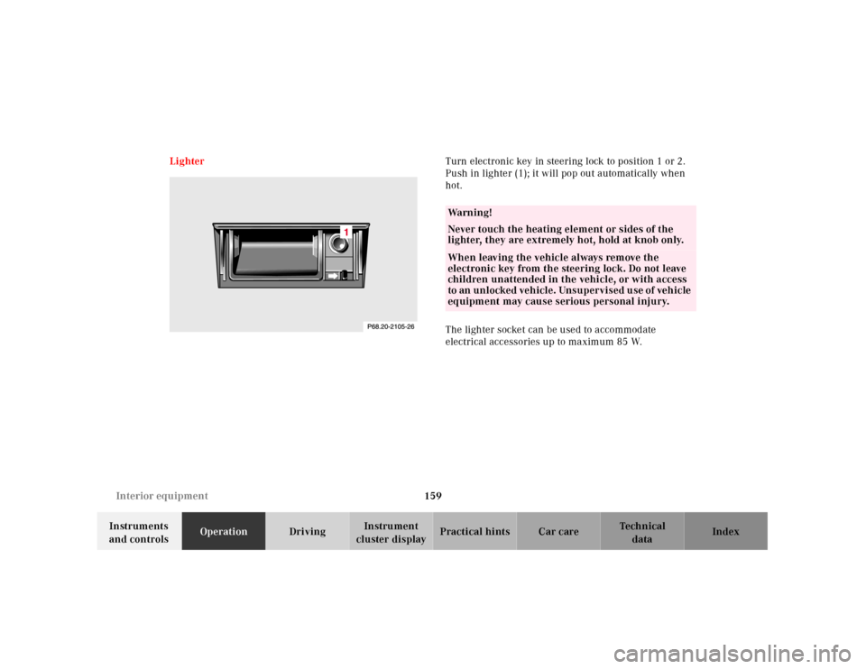
Push in lighter (1); it will pop out automatically when
hot.
The lighter socket can be used to accommodate
electrical accessories up to maximum 85 W.
Wa r n i n g !
Never touch the heating element or sides of the
lighter, they are extremely hot, hold at knob only.When leaving the vehicle always remove the
electronic key from the steering lock. Do not leave
children unattended in the vehicle, or with access
to an unlocked vehicle. Unsupervised use of vehicle
equipment may cause serious personal injury.
Page 167 of 329
164 Telephone
Te ch n ica l
data Instruments
and controlsOperationDrivingInstrument
cluster displayPractical hints Car care Index
Parcel net in front passenger footwell
A small convenience parcel net is located in the front
passenger footwell. It is for small and light items, such
as road maps, mail, etc..
Note:
With large objects stored in the parcel net do not slide
the seat fully forward, it could damage them.Telephone, general
Wa r n i n g !
Do not place heavy or fragile objects, or objects
having sharp edges, in the parcel net.In an accident, during hard braking or sudden
maneuvers, they could be thrown around inside
the vehicle, and cause injury to vehicle occupants.
Wa r n i n g !
A driver’s attention to the road must always be his/
her primary focus when driving. For your safety
and the safety of others, we recommend that you
pull over to a safe location and stop before placing
or taking a telephone call. If you choose to use the
telephone while driving, please use the hands-free
device and only use the telephone when road and
traffic conditions permit.Some ju ri sdi ctions proh ibit th e dri ver from usi ng a
cellular telephone while driving a vehicle.Bear in mind that at a speed of just 30 mph
(approximately 50 km/h), your vehicle is covering
a distance of approximately 50 feet (approximately
14 m) every second. Never operate radio transmitters equipped with a
built-in or attached antenna (i.e. without being
connected to an external antenna) from inside the
vehicle while the engine is running. Doing so could
lead to a malfunction of the vehicle’s electronic
system, possibly resulting in an accident and
personal injury.
Page 171 of 329
168 Garage door opener
Te ch n ica l
data Instruments
and controlsOperationDrivingInstrument
cluster displayPractical hints Car care Index
Rolling code programming:
To train a garage door opener (or other rolling code
devices) with the rolling code feature, follow these
instructions after completing the “Programming”
portion of this text. (A second person may make the
following training procedures quicker and easier.)
1. Locate training button on the garage door opener
motor head unit. Exact location and color of the
button may vary by garage door opener brand. If
there is difficulty locating the transmitting button,
reference to garage door opener operator’s manual.
2. Press “training” button on the garage door opener
motor head unit (which activated the “training
light”).
Note:
Following step 2, there are 30 seconds to initiate
step 3.3. Firmly press and release the programmed
integrated remote control transmit button. Press
and release same button a second time to complete
the training process. (Some garage door openers
may require you to do this procedure a third time to
complete the training.)
4. Confirm the garage door operation by pressing the
programmed button on the integrated remote
control transmitter.
Canadian programming:
During programming, your hand-held transmitter may
automatically stop transmitting. Continue to press and
hold the integrated remote control transmitter button
(note steps 2 through 4 in the “Programming” portion)
while you press and re-press (“cycle”) your hand-held
transmitter every two seconds until the frequency
signal has been learned. The indicator lamp will flash
slowly and then rapidly after several seconds upon
successful training.
Page 187 of 329
184 Tele Aid
Te ch n ica l
data Instruments
and controlsOperationDrivingInstrument
cluster displayPractical hints Car care Index
Roadside Assistance button
Located below the center armrest cover is the Roadside
Assistance button. Pressing and holding the
button (for longer than 2 seconds) will initiate a call to a
Mercedes-Benz Roadside Assistance dispatcher. The
button will flash while the call is in progress. The
message “ROADSIDE ASSISTANCE – CONNECTING
CALL” will appear in the multifunction display. When
the connection is established, the message “ROADSIDE
ASSISTANCE – CALL CONNECTED” appears in the
multifunction display. The Tele Aid system will transmit
data generating the vehicle identification number,
model, color and location (subject to availability of
cellular and GPS signals).
A voice connection between the Roadside Assistance
dispatcher and the occupants of the vehicle will be
established. When a voice connection is established the
audio system mutes and the message “TELE AID –
ROADSIDE ASSISTANCE CALL ACTIVE” appears in the
multifunction display. The nature of the need for
assistance can then be described. The Mercedes-Benz
Roadside assistance dispatcher will either dispatch a
qualified Mercedes-Benz technician or arrange to tow
your vehicle to the nearest Mercedes-Benz Center. For services such as la bor and/or towing charg es may a pply.
Refer to the Roadside Assistance manual for more
information.
These programs are only available in the USA:
•Sign and Drive services: Serv ices su ch as jump sta rt,
a few gallons of fuel or the replacement of a f lat tire
with the vehicle spare tire are obtainable,
•Remote Vehicle Diagnostics: This function permits
the Mercedes-Benz Roadside Assistance dispatcher
to download malfunction codes and actual vehicle
data.
Notes:
The indicator lamp in the Roadside Assistance
button remains illuminated in red for approx.
10 seconds during the system self-check after turning
electronic key in starter switch to position 2 (together
with the “SOS” button and the Information
button¡).
See system self-check on page 180 when the indicator
lamp does not light up in red or stays on longer than
approximately 10 seconds.
Page 188 of 329
185 Tele Aid
Te ch n ica l
data Instruments
and controlsOperationDrivingInstrument
cluster displayPractical hints Car care Index If the indicator lamp in the Roadside Assistance
button is illuminated continuously and there was
no voic e connec tion to th e Response Cente r establ ish ed,
then the Tele Aid system could not initiate an Roadside
Assistance call (e.g. the relevant cellular phone network
is not available). The message “ROADSIDE
ASSISTANCE – CALL FAILED” appears in the
multifunction display.
Roadside Assistance calls can be terminated using the
ìbutton on the multifunction steering wheel.
Information button ¡
Located below the center armrest cover is the
Information button¡. Pressing and holding the
button (for longer than 2 seconds) will initiate a call to
the Client Assistance Center. The button will flash while
the call is in progress. The message “INFO –
CONNECTING CALL” will appear in the multifunction
display. When the connection is established, the
message “INFO – CALL CONNECTED” appears in the
multifunction display. The Tele Aid system will transmit
data generating the vehicle identification number,
model, color and location (subject to availability of
cellular and GPS signals).A voice connection between the Client Assistance
Center representative and the occupants of the vehicle
will be established. When a voice connection is
established the audio system mutes and the message
“TELE AID – INFO CALL ACTIVE” appears in the
multifunction display. Information regarding the
operation of your vehicle, the nearest Mercedes-Benz
Center or Mercedes-Benz USA products and services is
ava il ab l e to you .
For more details concerning Tele Aid, please visit
www.mbusa.com and use your ID and password, sent to
you separately, to learn more (USA only).
Notes:
The indicator lamp in the Information button¡
remains illuminated in red for approx. 10 seconds
during the system self-check after turning electronic
key in starter switch to position 2 (together with the
“SOS” button and the Roadside Assistance button).
See system self-check on page 180 when the indicator
lamp does not light up in red or stays on longer than
approximately 10 seconds.
If the indicator lamp in the Information button¡ is
illuminated continuously and there was no voice
connection to the Response Center established, then the
Page 193 of 329
190 Steering lock
Te ch n ica l
data Instruments
and controlsOperationDrivingInstrument
cluster displayPractical hints Car care Index
Steering lock
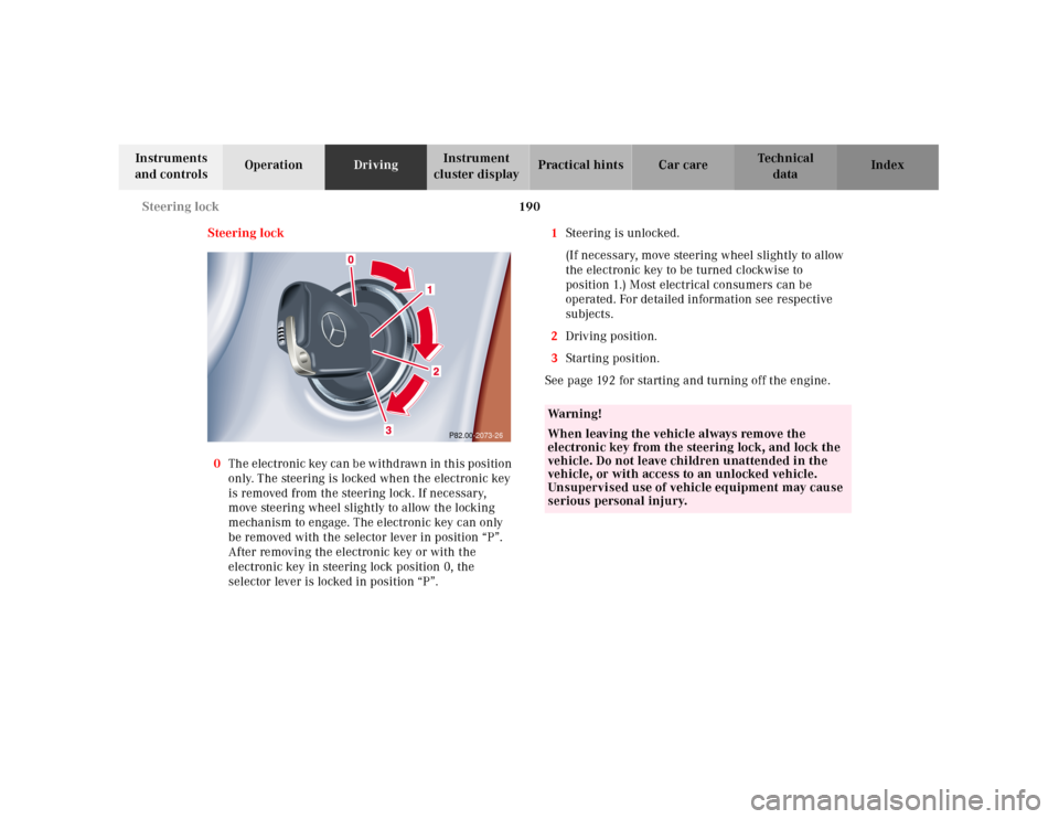
0The electronic key can be withdrawn in this position
only. The steering is locked when the electronic key
is removed from the steering lock. If necessary,
move steering wheel slightly to allow the locking
mechanism to engage. The electronic key can only
be removed with the selector lever in position “P”.
After removing the electronic key or with the
electronic key in steering lock position 0, the
selector lever is locked in position “P”.1Steering is unlocked.
(If necessary, move steering wheel slightly to allow
the electronic key to be turned clockwise to
position 1.) Most electrical consumers can be
operated. For detailed information see respective
subjects.
2Driving position.
3Starting position.
See page 192 for starting and turning off the engine.
P82.00-2073-26
Wa r n i n g !
When leaving the vehicle always remove the
electronic key from the steering lock, and lock the
vehicle. Do not leave children unattended in the
vehicle, or with access to an unlocked vehicle.
Unsupervised use of vehicle equipment may cause
serious personal injury.