Page 245 of 329
242 Malfunction and warning messages
Te ch n ica l
data Instruments
and controlsOperation DrivingInstrument
cluster displayPractical hints Car care Index
LIGHT SENSOR
With the electronic key removed and the driver’s door
open, a warning sounds and the message “SWITCH OFF
LIGHTS!” appears in the multifunction indicator if the
vehicle’s exterior lamps (except standing lamps) are not
switched off.STEER. WHEEL ADJUST.
For locking the adjustable telescoping steering column,
see page 78.
Line 1 Line 2
STEER. WHEEL ADJUST.
Page 247 of 329
244 Malfunction and warning messages
Te ch n ica l
data Instruments
and controlsOperation DrivingInstrument
cluster displayPractical hints Car care Index
ELEC. STABIL. PROG.
(Electronic stability program)
1 A malfunction has been detected in the system. Pressing the
accelerator pedal will require greater effort. Only partial engine
output will be available.
2 This message may be displayed if the power supply was
interrupted (battery disconnected or empty).
3 Synchronize ESP. See page 220
REMOVE KEY
This message plus an audible alarm indicate that the
electronic key is in steering lock position 0 or 1, and the
driver’s door is open.
Line 1 Line 2
DISPLAY DEFECTIVE VISIT WORKSHOP!
ELEC. STABIL. PROG. VISIT WORKSHOP!
1, 2, 3
Line 1 Line 2
RE MOVE KEY!
P54.30-3573-21
Page 250 of 329

247 Contents – Practical hints
Te ch n ica l
data Instruments
and controlsOperation DrivingInstrument
cluster displayPractical hintsCar care Index
Practical hintsFirst aid kit .....................................248
Shelf below rear window ..............248
Stowing things in
the vehicle ..................................248
Fuses ................................................249
Hood ................................................. 251
Checking engine oil level .............253
Automatic transmission
fluid level ...................................254
Coolant level ...................................254
Adding coolant ...........................255
Windshield washer / headlamp
cleaning system .........................256
Windshield and
headlamp washer
fluid mixing ratio .......................256Spare wheel, vehicle tools,
storage compartment ............... 257
Vehicle jack .................................... 258
Wheels ............................................ 259
Tire replacement ....................... 259
Rotating wheels ......................... 260
Spare wheel .................................... 261
Changing wheels ........................... 262
Tire inflation pressure ................. 267
Battery ............................................. 268
Jump starting ................................. 270
Towing the vehicle ........................ 272
Transmission selector lever,
manually unlocking ...................274
Exterior lamps ............................... 275
Headlamp assembly ...................276
Taillamp assemblies .................. 278Adjusting headlamp aim ...............280
Changing batteries in the
electronic main key ..................283
Synchronizing
remote control ............................285
Emergency operation of
sliding/pop-up roof ...................286
Manual release for
fuel filler flap .............................287
Replacing wiper blade
insert ...........................................287
Trunk lamp .....................................289
Roof rack .........................................289
Page 272 of 329

269 Battery
Te ch n ica l
data Instruments
and controlsOperation DrivingInstrument
cluster displayPractical hintsCar care Index Therefore, we strongly recommend that you have the
battery charge checked frequently, and corrected if
necessary, especially if you use the vehicle less than
approximately 200 miles (300 km) per month,
mostly for short distance trips, or if it is not used for
long periods of time.
Only charge a battery with a battery charger after the
battery has been disconnected from the vehicle’s
electrical circuit.
Always disconnect the battery negative lead first and
connect last.
When removing and connecting the battery, always
make sure that all electrical consumers are off and the
electronic key is in steering lock position 0. The battery
and its filler caps must always be securely installed
when the vehicle is in operation. During removal and
installation always protect the disconnected battery
positive (+) terminal with the cover attached to the
battery.
While the engine is running the battery terminal clamps
must not be loosened or detached, otherwise the
generator and other electronic components would be
damaged.Note:
After reconnecting the battery also set the clock (see
page 108), resynchronize the front seats (see page 49),
front seat head restraints (see page 49), the express
feature of the power windows (see page 148), the
sliding/pop-up roof (see page 150) and the electronic
stability program (ESP) (see page 220).
Battery recycling
Batteries contain material that can harm the
environment with improper disposal.
Large 12 Volt storage batteries contain lead.
Recycling of batteries is the preferred method of
disposal.
Many states require sellers of batteries to accept old
batteries for recycling.
Page 275 of 329

272 Towing
Te ch n ica l
data Instruments
and controlsOperation DrivingInstrument
cluster displayPractical hintsCar care Index
Towing the vehicle
Important!
When towing the vehicle, please, note the following:
With the automatic central locking activated and the
electronic key in steering lock position 2, the vehicle
d oors l ock if th e l ef t front wheel as well as t he righ t rear
wheel are turning at vehicle speeds of approx. 9 mph
(15 km/h) or more.
To prevent the vehicle door locks from locking,
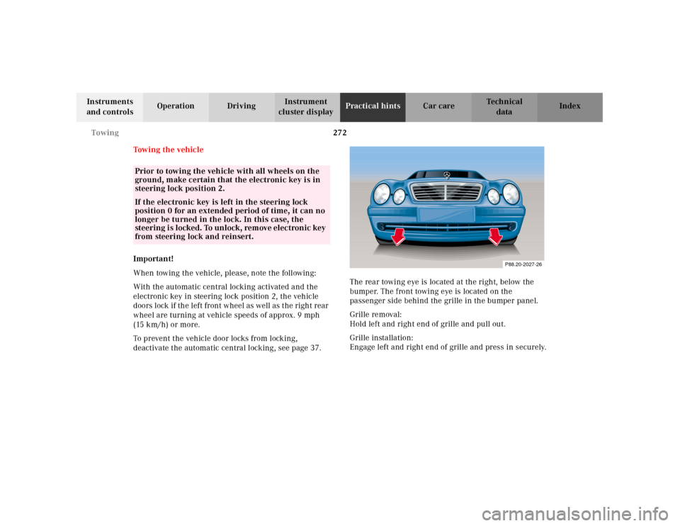
deactivate the automatic central locking, see page 37.The rear towing eye is located at the right, below the
bumper. The front towing eye is located on the
passenger side behind the grille in the bumper panel.
Grille removal:
Hold left and right end of grille and pull out.
Grille installation:
Engage left and right end of grille and press in securely.
Prior to towing the vehicle with all wheels on the
ground, make certain that the electronic key is in
steering lock position 2.If the electronic key is left in the steering lock
position 0 for an extended period of time, it can no
longer be turned in the lock. In this case, the
steering i s locked. To unlock, rem ove elec tronic key
from steering lock and reinsert.
P88.20-2027-26
Page 276 of 329

273 Towing
Te ch n ica l
data Instruments
and controlsOperation DrivingInstrument
cluster displayPractical hintsCar care Index We recommend that the vehicle be transported using
flat bed equipment. This method is preferable to other
types of towing.
The vehicle may be towed with all wheels on the ground
and the selector lever in position “N” for distances up to
30 miles (50 km) and at a speed not to exceed 30 mph
(50 km/h). The electronic key must be in steering lock
position 2.
To be certain to avoid a possibility of damage to the
transmission, however, we recommend the drive shaft
be disconnected at the rear axle drive f lange for any
towing beyond a short tow to a nearby garage.
Do not tow with sling-type equipment. Towing with
sling-type equipment over bumpy roads will damage
radiator and supports.
Use wheel lift, dolly, or flat bed equipment, with
electronic key in steering lock turned to position 0.Note:
To signal turns while being towed with hazard warning
flasher in use, turn electronic key in steering lock to
position 2 and activate combination switch for left or
right turn signal in usual manner – only the selected
turn signal will operate.
Upon canceling the turn signal, the hazard warning
flasher will operate again.
Caution!
If the vehicle is towed with the front axle raised, the
engine must be shut off (electronic key in steering lock
position 0 or 1). Otherwise, the ESP will immediately be
engaged and will apply the rear wheel brakes. Switch off
th e tow-away al arm (see page 44) a s well a s t he ESP (see
page 221).
Wa r n i n g !
With the engine not running, there is no power
assistance for the braking and steering systems. In
this case, it is important to keep in mind that a
considerably higher degree of effort is necessary to
brake and steer the vehicle.
Page 286 of 329
283 Electronic main key
Te ch n ica l
data Instruments
and controlsOperation DrivingInstrument
cluster displayPractical hintsCar care Index Changing batteries in the electronic main key
1Transmit buttons
2Lamp for battery check and function control
Checking batteries
If one of the transmit buttons (1) is pressed, the battery
check lamp (2) lights up briefly – indicating that the
batteries are in order.
Change batteries if the battery check lamp (2) does not
light up briefly.Changing batteries
Move locking tab (3) in direction of right arrow and
remove mechanical key (4, left arrow).
P80.20-2201-26
1
2
P80.35-2029-26
4
3
Page 287 of 329
284 Electronic main key
Te ch n ica l
data Instruments
and controlsOperation DrivingInstrument
cluster displayPractical hintsCar care Index
Insert mechanical key (4) in side opening (5) to open
latch. Press briefly (do not use mechanical key as lever)
to release battery compartment.
Remove mechanical key from side opening.
Carefully remove battery compartment in direction of
arrow(6).Change batteries (7), inserting new ones under contact
spring (8) with plus (+) side facing up.
Return battery compartment into housing until locked
in place and slide mechanical key back into electronic
main key.
P80.35-2025-26
5
4
6
P80.35-2027-26
78