2001 MERCEDES-BENZ CLK430 battery
[x] Cancel search: batteryPage 154 of 329
151 Interior equipment
Te ch n ica l
data Instruments
and controlsOperationDrivingInstrument
cluster displayPractical hints Car care Index Interior lighting
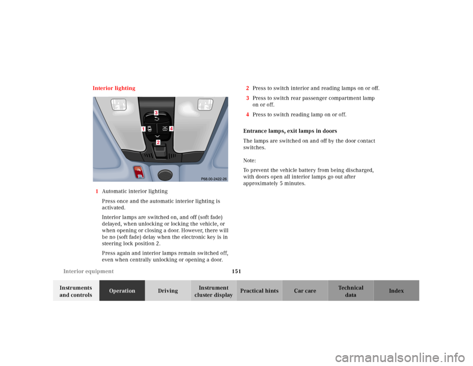
1Automatic interior lighting
Press once and the automatic interior lighting is
activated.
Interior lamps are switched on, and off (soft fade)
delayed, when unlocking or locking the vehicle, or
when opening or closing a door. However, there will
be no (soft fade) delay when the electronic key is in
steering lock position 2.
Press again and interior lamps remain switched off,
even when centrally unlocking or opening a door.2Press to switch interior and reading lamps on or off.
3Press to switch rear passenger compartment lamp
on or off.
4Press to switch reading lamp on or off.
Entrance lamps, exit lamps in doors
The lamps are switched on and off by the door contact
switches.
Note:
To prevent the vehicle battery from being discharged,
with doors open all interior lamps go out after
approximately 5 minutes.
1
4
32
Page 183 of 329
180 Tele Aid
Te ch n ica l
data Instruments
and controlsOperationDrivingInstrument
cluster displayPractical hints Car care Index
Te l e A i d
Important!
The initial activation of the Tele Aid system may only be
performed by completing the subscriber agreement and
placing an acquaintance call using the “SOS” button.
Failure to complete either of these steps will result in a
system that is not activated. If the system is not
activated the indicator lamp in the “SOS” button stays
on after turning electronic key in starter switch to
position 2 and the message “TELE AID – NOT
ACTIVATED” will be shown in th e multif unction display
for approx. 10 seconds.
If you have any questions regarding activation, please
call the Response Center at 1-800-756-9018 (in the USA)
or 1-888-923-8367 (in Canada).
(Te l ematic Alarm Identification on Demand)
The Tele Aid system consists of three types of response;
automatic and manual emergency, roadside assistance
and information.
The Tele Aid system is operational providing that the
vehicle’s battery is charged, properly connected, not
damaged and cellular and GPS coverage is available.The speaker volume of a Tele Aid call can be adjusted
when using the volume control on the multifunction
steering wheel, for raising press buttonæ and for
lowering press buttonç.
To activate, press the “SOS” button, the Roadside
Assistance button or t he Informa tion bu tton¡,
depending on the type of response required.
Shortly after the completion of your Acquaintance Call,
you will receive a user ID and password via first call
mail. By visiting www.mbusa.com and selecting “Tele
Aid” (USA only), you will have access to account
information, remote door unlock, Info Services* profile
and more.
* Optional – available only with COMANDSystem self-check
Initially, after turning the electronic key in starter
switch to position 2, malfunctions are detected and
indicated (the indicator lamps in the “SOS” button, the
Roadside Assistance button and the Information
button¡ stay on longer than 10 seconds or do not
come on). The message “TELE AID – VISIT
WORKSHOP” appears for approx. 10 seconds in the
multifunction display.
Page 194 of 329
191 Steering lock
Te ch n ica l
data Instruments
and controlsOperationDrivingInstrument
cluster displayPractical hints Car care Index Important!
If the el ectronic key is lef t in th e steering lock position 0
for an extended period of time, it can no longer be
turned in the lock. In this case, remove electronic key
from steering lock and reinsert.
Caution!
To prevent accelerated battery discharge and a possible
dead battery, always remove the electronic key from the
steering lock. Do not leave th e ele ctronic key in steering
lock position 0.Notes:
A warning sounds when the driver’s door is opened
while the electronic key is in steering lock position 1
or 0.
With the engine at idle speed, the charging rate of the
alternator (output) is limited.
It is therefore recommended that you turn off
unnecessary electrical consumers while driving in stop-
and-go tra f f ic. Th is pre cau tion h elps to avoid draining of
the battery.
Unnecessary strain on the battery and charging system
may be minimized by turning off the following power
consumers, for example: Heated seats, rear window
defroster. In addition, the automatic climate air volume
control should be set to the lowest position.
The steering lock can only be unlocked with the vehicle
battery properly charged and connected.
Page 213 of 329
210 Driving instructions
Te ch n ica l
data Instruments
and controlsOperationDrivingInstrument
cluster displayPractical hints Car care Index
Winter driving
Have your vehicle winterized at your authorized
Mercedes-Benz Center before the onset of winter.
•Change the engine oil if the engine contains an oil
which is not approved for winter operation. For
viscosity (SAE/CCMC class) and filling quantity,
see page 305.
•Check engine coolant anticorrosion/antifreeze
concentration.
•Additive for the windshield washer and headlamp
cleaning system: Add MB Concentrate “S” to a
premixed windshield washer solvent/antifreeze
which is formulated for below freezing
temperatures, see page 256.
•Test battery: Battery capacity drops with decreasing
ambient temperature. A well charged battery helps
to ensure that the engine can be started, even at low
ambient temperatures.
•Tires: We recommend M+S rated radial-ply tires on
all four wheels for the winter season. Observe
permissible maximum speed for M+S rated
radial-ply tires and the legal speed limit.In winter operation, the maximum effectiveness of the
antilock brake system (ABS) or of the electronic stability
program (ESP) can only be achieved with M+S rated
radial-ply tires and / or snow chains recommended by
Mercedes-Benz. Snow chains maximize performance.
For driving instructions with snow chains see page 209.
Deep water
Caution!
Do not drive t hrou gh f lood ed a rea s or water of u nk nown
depth.
If you must drive through deep water, drive slowly to
prevent water from entering the engine compartment or
passenger compartment, being ingested by the air
intake, possibly causing damage to electrical
components or wiring, to engine or transmission that is
not covered by the Mercedes-Benz Limited Warranty.
Page 223 of 329
220 Driving systems
Te ch n ica l
data Instruments
and controlsOperationDrivingInstrument
cluster displayPractical hints Car care Index
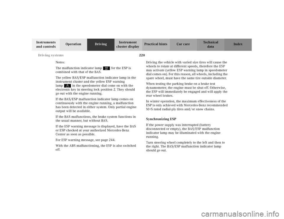
Notes:
The malfunction indicator lamp¿ for the ESP is
combined with that of the BAS.
The yellow BAS/ESP malfunction indicator lamp in the
instrument cluster and the yellow ESP warning
lampv in the speedometer dial come on with the
electronic key in steering lock position 2. They should
go out with the engine running.
If the BAS/ESP malfunction indicator lamp comes on
continuously with the engine running, a malfunction
has been detected in either system. Only partial engine
output will be available.
If the BAS malfunctions, the brake system functions in
the usual manner, but without BAS.
If the ESP warning message is displayed, have the BAS
or ESP checked at your authorized Mercedes-Benz
Center as soon as possible.
For ESP warning message, see page 244.
With the ABS malfunctioning, the ESP is also switched
off.Driving the vehicle with varied size tires will cause the
wheels to rotate at different speeds, therefore the ESP
may activate (yellow ESP warning lamp in speedometer
dial comes on). For this reason, all wheels, including the
spare wheel, must have the same tire outside diameter.
When testing the parking brake on a brake test
dynamometer, the engine must be shut off. Otherwise,
the ESP will immediately be engaged and will apply the
rear wheel brakes.
In winter operation, the maximum effectiveness of the
ESP is only achieved with Mercedes-Benz recommended
M+S rated radial-ply tires and / or snow chains.
Synchronizing ESP
If the power supply was interrupted (battery
disconnected or empty), the BAS/ESP malfunction
indicator lamp may be illuminated with the engine
running.
Turn steering wheel completely to the left and then to
the right. The BAS/ESP malfunction indicator lamp
should go out.
Page 230 of 329

227 Contents – Instrument cluster display
Te ch n ica l
data Instruments
and controlsOperation DrivingInstrument
cluster displayPractical hints Car care Index
Instrument cluster displayMalfunction and indicator
lamps in the
instrument cluster ....................228
On-board diagnostic system
Check engine malfunction
indicator lamp .............................228
Brake warning lamp ..................229
Supplemental restraint
system (SRS)
indicator lamp .............................230
Fuel reserve and fuel cap
placement warning ....................230
Electronic stability program
(ESP) — warning lamp ............... 231
BAS/ESP malfunction
indicator lamp ............................. 231ABS malfunction
indicator lamp ............................ 231
Telescoping steering column –
indicator lamp ............................ 232
Seat belt warning lamp ............. 232
Malfunction and indicator lamps
in the center console ............... 232
AIRBAG OFF
indicator lamp ............................ 232
Malfunction and warning
messages in the
multifunction display .............. 233
DISPLAY DEFECTIVE
(engine control unit) ................. 234
DISPLAY DEFECTIVE
(several systems) ....................... 234
BATTERY/ALTERNATOR .......... 235
ABS-SYSTEM .............................. 236
BRAKE ASSIST ........................... 236BRAKE LINING WEAR ..............237
BRAKE FLUID .............................237
PARKING BRAKE .......................238
ENGINE FAN ...............................238
COOLANT
(coolant level) .............................239
COOLANT TEMP.
(coolant temperature) ................240
LIGHTING SYSTEM .................... 241
LIGHT SENSOR ...........................242
STEER. WHEEL ADJUST. ...........242
ENGINE OIL LEVEL ...................243
ELEC. STABIL. PROGRAM.
(Electronic stability
program) ......................................244
REMOVE KEY .............................244
WASHER FLUID .........................245
TELE AID .....................................246
Page 238 of 329
235 Malfunction and warning messages
Te ch n ica l
data Instruments
and controlsOperation DrivingInstrument
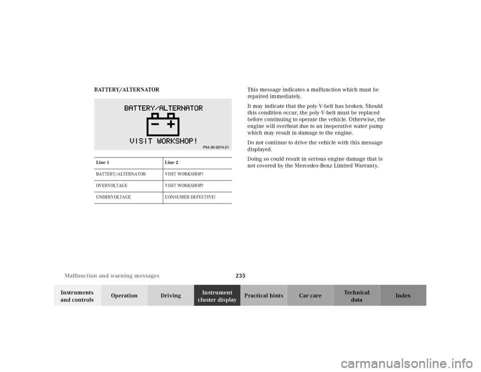
cluster displayPractical hints Car care Index BATTERY/ALTERNATORThis message indicates a malfunction which must be
repaired immediately.
It may indicate that the poly-V-belt has broken. Should
this condition occur, the poly-V-belt must be replaced
before continuing to operate the vehicle. Otherwise, the
engine will overheat due to an inoperative water pump
which may result in damage to the engine.
Do not continue to drive the vehicle with this message
displayed.
Doing so could result in serious engine damage that is
not covered by the Mercedes-Benz Limited Warranty.
Line 1 Line 2
BATTERY/ALTERNATOR VISIT WORKSHOP!
OVERVOLTAGE V ISIT WORKS HOP !
UNDERVOLTAGE CONSUMER DEFECTIVE!
Page 247 of 329
244 Malfunction and warning messages
Te ch n ica l
data Instruments
and controlsOperation DrivingInstrument
cluster displayPractical hints Car care Index
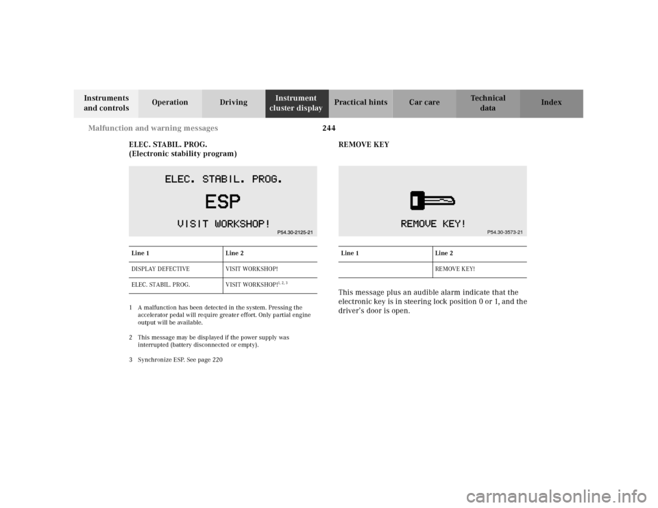
ELEC. STABIL. PROG.
(Electronic stability program)
1 A malfunction has been detected in the system. Pressing the
accelerator pedal will require greater effort. Only partial engine
output will be available.
2 This message may be displayed if the power supply was
interrupted (battery disconnected or empty).
3 Synchronize ESP. See page 220
REMOVE KEY
This message plus an audible alarm indicate that the
electronic key is in steering lock position 0 or 1, and the
driver’s door is open.
Line 1 Line 2
DISPLAY DEFECTIVE VISIT WORKSHOP!
ELEC. STABIL. PROG. VISIT WORKSHOP!
1, 2, 3
Line 1 Line 2
RE MOVE KEY!
P54.30-3573-21