Page 82 of 329

79 Rear view mirrors
Te ch n ica l
data Instruments
and controlsOperationDrivingInstrument
cluster displayPractical hints Car care Index Inside rear view mirror
Manually adjust the mirror.
Use your inside mirror to determine the size and
distance of objects seen in the passenger side convex
mirror.
Antiglare night position
With the electronic key in steering lock position 2, the
mirror reflection brightness responds to changes in
light sensitivity.
With gear selector lever in position “R”, or with the
interior lamp switched on, the mirror brightness does
not respond to changes in light sensitivity.Note:
The automatic antiglare function does not react, if
incoming light is not aimed directly at sensors in the
mirror.
Wa r n i n g !
In the case of an accident liquid electrolyte may
escape the mirror housing when the mirror glass
breaks.Electrolyte has an irritating effect. Do not allow the
liquid come into contact with eyes, skin, clothing,
or respiratory system. In cases it does, imm edi ately
flush affected area with water, and seek medical
help if necessary.
Page 83 of 329

80 Rear view mirrors
Te ch n ica l
data Instruments
and controlsOperationDrivingInstrument
cluster displayPractical hints Car care Index
Exterior rear view mirrors
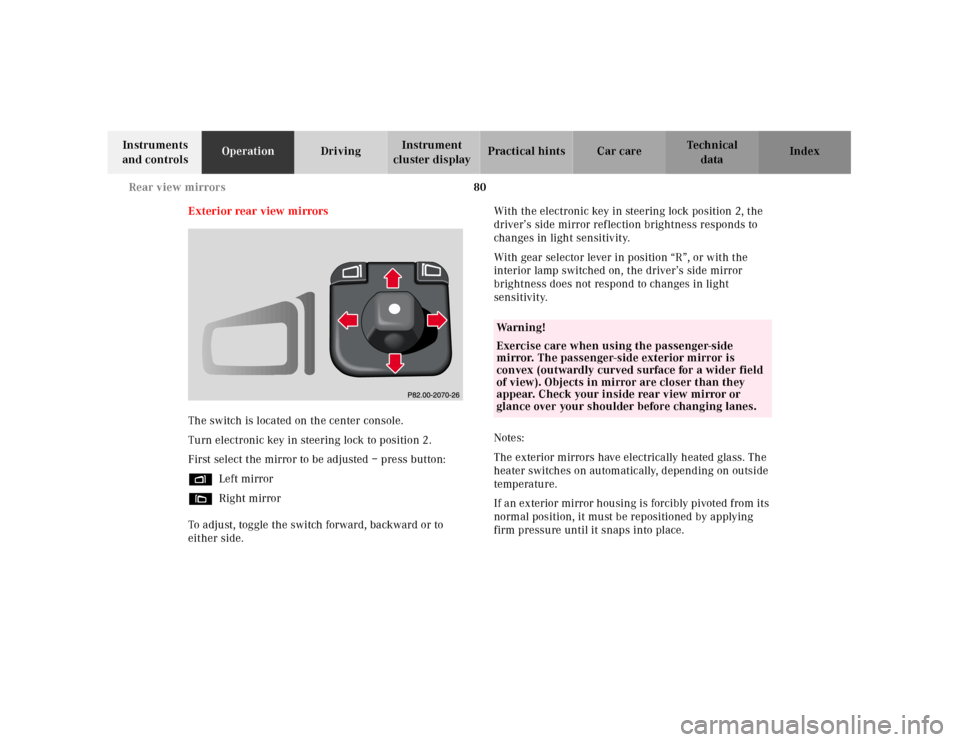
The switch is located on the center console.
Turn electronic key in steering lock to position 2.
First select the mirror to be adjusted – press button:
%Left mirror
&Right mirror
To adjust, toggle the switch forward, backward or to
either side.With the electronic key in steering lock position 2, the
driver’s side mirror reflection brightness responds to
changes in light sensitivity.
With gear selector lever in position “R”, or with the
interior lamp switched on, the driver’s side mirror
brightness does not respond to changes in light
sensitivity.
Notes:
The exterior mirrors have electrically heated glass. The
heater switches on automatically, depending on outside
temperature.
If an exterior mirror housing is forcibly pivoted from its
normal position, it must be repositioned by applying
firm pressure until it snaps into place.
Wa r n i n g !
Exercise care when using the passenger-side
mirror. The passenger-side exterior mirror is
convex (outwardly curved surface for a wider field
of view). Objects in mirror are closer than they
appear. Check your inside rear view mirror or
glance over your shoulder before changing lanes.
Page 84 of 329
81 Rear view mirrors
Te ch n ica l
data Instruments
and controlsOperationDrivingInstrument
cluster displayPractical hints Car care Index Important!
Electrolyte drops coming into contact with the vehicle
paint finish can only be completely removed while in
their liquid state, by applying plenty of water.Storing mirror positions in memory
The exterior rear view mirror positions are stored in
memory with the seat/head restraint position and can
be recalled when necessary, see page 48.
Wa r n i n g !
In the case of an accident liquid electrolyte may
escape the mirror housing when the mirror glass
breaks.Electrolyte has an irritating effect. Do not allow the
liquid come into contact with eyes, skin, clothing,
or respiratory system. In c ases it does, i mmedi ately
flush affected area with water, and seek medical
help if necessary.
Page 88 of 329
85 Instrument cluster
Te ch n ica l
data Instruments
and controlsOperationDrivingInstrument
cluster displayPractical hints Car care Index 1Push buttons V and W for intensity of
instrument lamps, see page 87
2Push button Jfor resetting trip odometer, see
page 89, or to acknowledge a malfunction or
warning message, see page 106
3Coolant temperature gauge, see page 88
4Fuel gauge with reserve and fuel cap placement
warning lamp, see page 230
5Outside temperature indicator, see page 88
6Left turn signal indicator lamp, see combination
switch on page 119
7ESP warning lamp, see page 2318Speedometer
9Trip odometer, see page 89
10Main odometer
11Multifunction indicator, see page 233
or FSS indicator, see page 111
or engine oil level indicator, see page 114
12Right turn signal indicator lamp, see combination
switch on page 119
13Tachometer, see page 89
14Gear range indicator display, see selector lever
positions, see page 196
15Clock, see page 108
Page 89 of 329

86 Instrument cluster
Te ch n ica l
data Instruments
and controlsOperationDrivingInstrument
cluster displayPractical hints Car care Index
Indicator lamps in the instrument cluster
High beam
ABS malfunction, see page 231
Brake fluid low (except Canada),
Parking brake engaged, see page 237
Brake fluid low (Canada only),
Parking brake engaged, see page 237
BAS malfunction, see page 231
ESP malfunction, see page 231
ESP. Adjust driving to road condition,
see page 231
Fasten seat belts, see page 232Telescoping steering column not locked,
see page 232
SRS malfunction, see page 230
Engine malfunction indicator lamp. If the
“CHECK ENGINE” malfunction indicator
lamp comes on when the engine is running,
it indicates a malfunction of the fuel
management system, emission control
system, systems which impact emissions, or
the fuel cap is not closed tight. In all cases,
we recommend that you have the
malfunction checked as soon as possible, see
page 230
Function indicator lamp on the center console
Front passenger airbag automatically
switched off, see page 232
ABSBRAKEBAS
ESP
SRSCHECK
ENGINE
Page 90 of 329
87 Instrument cluster
Te ch n ica l
data Instruments
and controlsOperationDrivingInstrument
cluster displayPractical hints Car care Index Activating instrument cluster
The instrument cluster is activated by:
•Opening the door.
•Pressing buttonJ, Vor Won the instrument
cluster.
•Turning the electronic key in steering lock to
position 1 or 2.
•Switching on the exterior lamps.
Display illumination
The display for temperature, odometer, multifunction
indicator, FSS indicator and clock is illuminated briefly
when opening the driver’s door.
The display illumination brightness responds
automatically according to changes in the surrounding
light sensitivity.
To briefly illuminate the display (with electronic key
removed or in steering lock position 0), press buttonJ.Instrument lamps
Activate the instrument cluster.
Press V or W button to vary intensity of instrument
lamps.
P54.30-2767-26
Page 107 of 329
104 Multifunction steering wheel, multifunction display
Te ch n ica l
data Instruments
and controlsOperationDrivingInstrument
cluster displayPractical hints Car care Index
Trip computer 1“AFTER START” – trip odometer records distance
from first engine start after more than five hours of
electronic key not being in steering lock position 2
2“AFTER RESET” – trip odometer records distance
from first engine start until it is reset
3Estimated driving range remaining and fuel tank
contents
4Distance covered “AFTER START” respectively
“AFTER RESET”
5Elapsed time “AFTER START” respectively
“AFTER RESET”
6Average speed “AFTER START” respectively
“AFTER RESET”
7Average fuel consumption “AFTER START”
respectively “AFTER RESET”
Page 110 of 329

107 Multifunction steering wheel, multifunction display
Te ch n ica l
data Instruments
and controlsOperationDrivingInstrument
cluster displayPractical hints Car care Index Should any malfunctions be stored while driving, they
will reappear in the display (2) when the electronic key
is in steering lock position 0 or removed from the
steering lock.
Specific malfunctions can be recalled by pressing
button J. Each malfunction or warning message must
be acknowledged by pressing button J. Once all
messages are cancelled, the odometer display should
reappear.
Pressing the J button in the instrument cluster
immediately switches to the next malfunction message.
The malfunction message memory will be cleared when
the electronic key is turned in the steering lock to
position 1 or 2. Should any subsequent malfunctions
occur, they will be displayed in the malfunction
message memory.
Pressing the è or ÿ button displays the next or
previous system.Important!
Malfunctions and warning messages are only indicated
for certain systems and displayed to a low level of detail.
The malfunction and warning messages are simply a
reminder with respect to the operation of certain
systems and do not replace the driver’s responsibility to
maintain the vehicle’s operating safety by having all
required maintenance and safety checks performed on
the vehicle and by bringing the vehicle to an authorized
Mercedes-Benz Center to address the malfunction and
warning messages. See page 233.