2001 MERCEDES-BENZ CLK CABRIOLET turn signal
[x] Cancel search: turn signalPage 8 of 341

5 ContentsSpare wheel, vehicle tools,
storage compartment ................260
Vehicle jack ..................................... 261
Wheels .............................................262
Tire replacement ........................262
Rotating wheels ..........................263
Spare wheel ....................................264
Changing wheels ...........................266
Tire inflation pressure .................. 271
Battery .............................................272
Jump starting .................................. 274
Towing the vehicle ......................... 276
Exterior lamps ................................280
Headlamp assembly ................... 281
Taillamp assemblies ..................283
Adjusting headlamp aim ...............285
Changing batteries in
the electronic main key ...........288
Synchronizing
remote control ...........................290Raising soft top manually ............ 291
Antenna .......................................... 298
Manual release for
fuel filler flap ............................ 298
Trunk lamp ..................................... 299
Replacing wiper
blade insert ............................... 299
Vehicle careCleaning and care
of the vehicle ............................. 302
Power washer ............................. 303
Paintwork, painted body
components ................................ 303
Engine cleaning ......................... 304
Tar stains .................................... 304
Vehicle washing ......................... 304
Ornamental moldings ............... 304
Headlamps, taillamps,
turn signal lenses ...................... 305Window cleaning .......................305
Plastic and rubber parts ............305
Wiper blade .................................305
Light alloy wheels ......................305
Instrument cluster .....................306
Steering wheel and
gear selector lever ......................306
Cup holder ...................................306
Seat belts .....................................306
Headliner .....................................306
Upholstery ...................................307
Hard plastic trim items .............307
Plastic and rubber parts ............307
Wind screen ...............................307
Rubber weatherstrip .................307
Soft top .........................................308
Page 33 of 341

30 Central locking system
Te ch n ica l
data Instruments
and controlsOperationDrivingInstrument
cluster displayPractical hints Car care Index
Locking and unlocking with remote control
Unlocking:
Press transmit button Œ. All turn signal lamps blink
once to indicate that the vehicle is unlocked.
The remote control can be programmed for two kinds of
unlocking modes (see below):
Selective unlocking mode –
Press transmit button Œ once to unl ock d river’s d oor
and fuel filler flap.
Press transmit button Πtwice to unlock both doors,
fuel filler flap, and trunk.
Global unlocking mode –
Press transmit button Πonce to unlock both doors,
fuel filler flap, and trunk.
Notes:
If the trunk was previously locked separately, it will
remain locked, see page 38.The presently active unlocking mode (selective or
global) can only be determined by unlocking the vehicle
with the remote control (see below for changing mode).
If within 40 seconds of unlocking with the remote
control, neither door nor trunk is opened, the electronic
key is not inserted in the steering lock, or the central
locking switch is not activated, the vehicle will
automatically lock.
Locking:
Press transmit button ‹ once. All turn signal lamps
blink three times to indicate that the vehicle is locked.
If they do not blink three times, a door or trunk is not
properly closed.
Note:
If the vehicle cannot be locked or unlocked by pressing
the transmit button, then it may be necessary to change
the batteries in the electronic main key (if ok, battery
check lamp in electronic main key will light briefly
when pressing transmit button) or to synchronize the
remote control, see pages 288 and 290.
Page 86 of 341

83 Instrument cluster
Te ch n ica l
data Instruments
and controlsOperationDrivingInstrument
cluster displayPractical hints Car care Index 1Push buttonsVandWfor intensity of instrument
lamps, see page 85
2Push buttonJ for resetting trip odometer, see
page 87, or to acknowledge a malfunction or
warning message, see page 104.
3Coolant temperature gauge, see page 86
4Fuel gauge with reserve and fuel cap placement
warning lamp, see page 230
5Outside temperature indicator, see page 86
6Left turn signal indicator lamp, see combination
switch on page 117
7ESP warning lamp, see page 2318Speedometer
9Trip odometer, see page 87
10Main odometer
11Multifunction indicator, see page 88
or FSS indicator, see page 109
or engine oil level indicator, see page 112
12Right turn signal indicator lamp, see combination
switch on page 117
13Tachometer, see page 87
14Gear range indicator display, see selector lever
positions on page 198
15Clock, see page 106
Page 112 of 341

109 Flexible service system
Te ch n ica l
data Instruments
and controlsOperationDrivingInstrument
cluster displayPractical hints Car care Index Flexible service system (FSS)
(service indicator)
The FSS permits a flexible service schedule that is
directly related to the operating conditions of the
vehicle.
The symbol 9 or ½ appears together with a
message in the multifunction indicator prior to the next
suggested service. Depending on operating conditions
throughout the year, the next service is calculated and
displayed in days or distance remaining.The message is displayed for approx. 10 seconds when
turning the electronic key in steering lock to position 2,
or while driving when reaching the service warning
threshold.
The symbols and messages indicate the type of service
to be performed:
9Service A
½Service B
One of t he following messages will appe ar in th e displ ay
(e.g. Service A):
“SERVICE A – IN xx DAYS”
“SERVICE A – IN xx MILES” (Canada: KM)
“SERVICE A – EXCEEDED BY xx DAYS”
“SERVICE A – EXCEEDED BY xx MILES” (Canada: KM)
“SERVICE A – DUE NOW”
The next service due date is displayed either in days or
in miles, depending on your driving style.
Once th e su gge sted service term ha s passed, th e symb ol
and message appear for approx. 30 sec onds and a signal
sounds every time when turning the electronic key in
steering lock to position 2.
10
0
406080
60
40
mph
20km/h
20100
120
140160
80
100
180
200
220
240 160 120 140
Page 114 of 341

111 Flexible service system
Te ch n ica l
data Instruments
and controlsOperationDrivingInstrument
cluster displayPractical hints Car care Index Following a completed A or B service the
Mercedes-Benz Center sets the counter mileage to
10 000 miles (Canada: 15 000 km) and 365 days.
The counter can also be set by any individual. To do so:
Turn the electronic key in steering lock to position 2.
To call up the trip odometer and main odometer, press
button è or ÿ on the multifunction steering
wheel until the display appears. See page 92.
Press button j or k until the FSS indicator
appears.
Press button Jon the instrument cluster for
approximately 2 seconds.The multifunction display will show the question:
“DO YOU WANT TO RESET SERVICE INTERVAL? –
CONFIRM BY PRESSING R”
Press button J on the instrument cluster again, and
hold until a signal sounds. The message “SERVICE
INTERVAL HAS BEEN RESET” appears in the
multifunction display.
The new service indicator is displayed with the reset
distance of 10 000 miles (Canada 15 000 km).
If the FSS counter was inadvertently reset, have a
Mercedes-Benz Center correct it.
However you choose to set your reference numbers, the
scheduled services as posted in the Service Booklet
must be followed to properly care for your vehicle.
Page 120 of 341

117 Combination switch
Te ch n ica l
data Instruments
and controlsOperationDrivingInstrument
cluster displayPractical hints Car care Index Combination switch
1Low beam (exterior lamp switch position B)
2High beam (exterior lamp switch position B)3High beam flasher (high beam available
independent of exterior lamp switch position)
4Turn signals, right
5Turn signals, left
To signal minor directional changes, such as changing
lanes on a highway, move combination switch to the
point of resistance only and hold it there.
To operate the turn signals continuously, move the
combination switch past the point of resistance (up or
down). The switch is automatically canceled when the
steering wheel is turned to a large enough degree.
Turn signal failure
If one of the turn signals fails, the turn signal indicator
system f lashes and sounds at a faster than normal rate.
P54.25-2034-26
2
3
4
4
5
5
1
Page 122 of 341
119 Hazard warning flasher
Te ch n ica l
data Instruments
and controlsOperationDrivingInstrument
cluster displayPractical hints Car care Index Windshield wiper smears
If the windshield wiper smears the windshield, even
during rain, activate the washer system as often as
necessary. The fluid in the washer reservoir should be
mixed in the correct ratio, see page 259.
Blocked windshield wiper
If the windshield wiper becomes blocked (for example,
due to snow), switch off the wiper.
For safety reasons before removing ice or snow, remove
electronic key from steering lock. Remove blockage.
Activate combination switch again (electronic key in
steering lock position 1).Hazard warning flasher switch
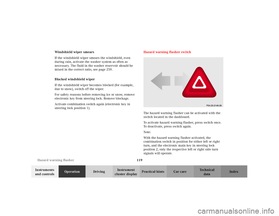
The hazard warning f lasher can be activated with the
switch located in the dashboard.
To activate hazard warning flasher, press switch once.
To deactivate, press switch again.
Note:
With the hazard warning flasher activated, the
combination switch in position for either left or right
turn, and the electronic main key in steering lock
position 2, only the respective left or right side turn
signals will operate.
Page 162 of 341

159 Garage door opener
Te ch n ica l
data Instruments
and controlsOperationDrivingInstrument
cluster displayPractical hints Car care Index For operation in the USA only: This device complies
with Part 15, Subpart C, Section 209 of the FCC Rules.
Operation is subject to the following two conditions:
(1) This device may not cause harmful interference, and
(2) this device must accept any interference received,
including interference that may cause undesired
operation.
WARNING: Changes or modification not expressly
a p pr ove d by pa rt y r e s po n si b l e f or c o mpl ia n c e c o u l d vo i d
the user’s authority to operate the equipment.
Programming or reprogramming the integrated
remote control:
1. Turn electronic key in steering lock to position 1
or 2.
2. Hold the end of the hand-held transmitter of the
d evice you w ish to train approxim ately 2 to 5 inch es
(5 cm to 12 cm) away from the surface of the
integrated remote control located on the inside rear
view mirror, keeping the indicator lamp in view.3. Using both hands, simultaneously push the hand-
held transmitter button and the desired integrated
remote control button. Do not release the buttons
until completing step 4.
4. The indicator lamp on the integrated remote control
will flash, first slowly and then rapidly. When the
indicator lamp f lashes rapidly, both buttons may be
released (the rapid flashing lamp indicates
successful programming of the new frequency
signal). To program the remaining two buttons,
follow steps 1 though 4.
Note:
If after repeated attempts, you do not successfully
program the integrated remote control device to learn
the signal of the hand-held transmitter, the garage door
opener could be equipped with the “rolling code
feature”.