Page 300 of 424
294 Malfunction and indicator lamps
Te ch n ica l
data Instruments
and controlsOperation DrivingInstrument
cluster displayPractical hints Car care Index
ABS malfunction indicator lamp
The ABS malfunction indicator lamp in the
instrument cluster comes on with the
electronic key in starter switch position 2
and should go out with the engine running.
When the ABS malfunction indicator lamp symbol and
warning in the instrument cluster remains illuminated
while the engine is running, it indicates that the ABS
has detected a malfunction and has switched off. In this
case, the brake system functions in the usual manner,
but without antilock assistance.
A malfunctioning ABS control unit can possibly affect
the operation of other systems (e.g. Parktronic,
Navigation, Automatic transmission). Be guided
a ccord ingly w ith respect to t he u se of th ose systems and
have the system checked at your authorized
Mercedes-Benz Center as soon as possible.With the ABS malfunctioning, the BAS and ESP are also
switched off. The malfunction indicator lamps and
malfunction messages in the multifunction display
come on with the engine running.
If the charging voltage falls below 10 volts, the
malfunction indicator lamp comes on and the ABS is
sw itched of f. Wh en t he voltage is a bove th is value a gain,
the malfunction indicator lamp should go out and the
ABS is operational.
Have the system checked at your authorized
Mercedes-Benz Center as soon as possible.
See page 269 for notes on antilock brake system (ABS).
ABS
Page 301 of 424
295 Malfunction and indicator lamps
Te ch n ica l
data Instruments
and controlsOperation DrivingInstrument
cluster displayPractical hints Car care Index Electronic stability program (ESP) — warning lamp
The yellow ESP warning lamp in the
speedometer dial comes on with the
electronic key in starter switch position 2. It
should go out with engine running.
If the ESP malfunction indicator lamp remains
illuminated with the engine running, a malfunction has
been detected in the system. Pressing the accelerator
pedal will require greater effort. Only partial engine
output will be available.
See elec tronic sta bil ity program (ESP) on pa ge 271 if t he
warning lamp lights up or f lashes when the vehicle is
moving.Distronic (DTR) – warning lamp
With the electronic key in starter switch
position 2, the distance warning lamp in the
speedometer dial comes on and goes out
with the engine running.
See Distronic (DTR) system on page 321 for possible
malfunction messages.
Note:
The distance warning lamp is without a warning
function on vehicles without distronic (DTR).
Page 309 of 424
303 Malfunction and warning messages
Te ch n ica l
data Instruments
and controlsOperation DrivingInstrument
cluster displayPractical hints Car care Index ELEC. STABIL. PROG.
(Electronic stability program)
* C = Category, see page 2971 The display or the system is malfunctioning.
2 A malfunction has been detected in the system. Pressing the
accelerator pedal will require greater effort. Only partial engine
output will be available.
3 The enhanced vehicle stability offered by ESP and the torque
reduction feature are unavailable.
4 This message may be displayed if the power supply was
interrupted (battery disconnected or empty). Synchronize ESP, see
page 272.
Line 1 Line 2 C*
DISPLAY DEFECTIVE VISIT WORKSHOP!
1
2
ELEC. STABIL. PROG. VISIT WORKSHOP!
2, 3, 4
2
Page 321 of 424
315 Malfunction and warning messages
Te ch n ica l
data Instruments
and controlsOperation DrivingInstrument
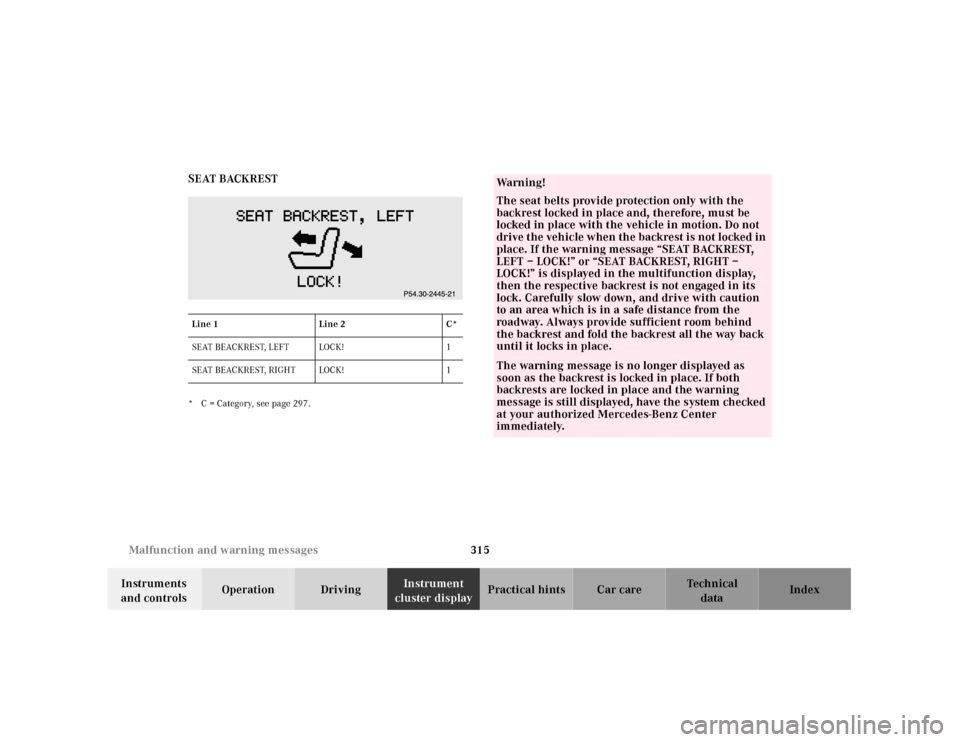
cluster displayPractical hints Car care Index SEAT BACKREST
* C = Category, see page 297.Line 1 Line 2 C*
SEAT BEACKREST, LEFT LOCK! 1
SEAT BEACKREST, RIGHT LOCK! 1
Wa r n i n g !
The seat belts provide protection only with the
backrest locked in place and, therefore, must be
locked in place with the vehicle in motion. Do not
drive the vehicle when the backrest is not locked in
place. If the warning message “SEAT BACKREST,
LEFT – LOCK!” or “SEAT BACKREST, RIGHT –
LOCK!” is displayed in the multifunction display,
then the respective backrest is not engaged in its
lock. Carefully slow down, and drive with caution
to an area which is in a safe distance from the
roadway. Always provide sufficient room behind
the backrest and fold the backrest all the way back
until it locks in place.The warning message is no longer displayed as
soon as the backrest is locked in place. If both
backrests are locked in place and the warning
message is still displayed, have the system checked
at your authorized Mercedes-Benz Center
immediately.
Page 323 of 424
317 Malfunction and warning messages
Te ch n ica l
data Instruments
and controlsOperation DrivingInstrument
cluster displayPractical hints Car care Index HOOD
* C = Category, see page 297.See page 328 for hood.TELE AID
1 The Tele Aid system consists of three types of response; automatic
and manual emergency, roadside assistance and information. With
this message displayed, one or more functions may not be
av a i l a b l e .
See page 210 for notes on the Tele Aid.If a malfunction is indicated as outlined above, have the
system checked at the nearest Mercedes-Benz Center as
soon as possible.
Line 1 Line 2 C*
ENGINE HOOD OPEN! 2
P54.30-2560-21
Line 1 Line 2 C*
TELE AID VISIT WORKSHOP!
1
1
Page 342 of 424

336 Jack
Te ch n ica l
data Instruments
and controlsOperation DrivingInstrument
cluster displayPractical hintsCar care Index
Jack
To prepare the jack for use:
Remove the jack from the spare wheel well under the
trunk floor, push the crank handle up and turn
clockwise until it engages (operational position).Storing the jack in the trunk:
Retract the jack arm to the base of the jack, push the
crank handle up and turn counterclockwise to the end
of the stop (storage position).
P58.10-2001-26
Wa r n i n g !
The jack is designed exclusively for jacking up the
veh icle at th e jack tu bes bu ilt into eit her side of th e
vehicle. To help avoid personal injury, use the jack
only to lift the vehicle during a wheel change.
Never get beneath the vehicle while it is supported
by t he jack. Keep hands and feet away from th e area
under the lifted vehicle. Always firmly set parking
brake and block wheels before raising vehicle with
jack.Do not disengage parki ng brake wh ile th e vehi cle i s
raised. Be certain that the jack is always vertical
when in use, especially on hills. Always try to use
the jack on level surface. Be sure that the jack arm
is fully inserted in the jack tube. Always lower the
vehicle onto sufficient capacity jackstands before
working under the vehicle.
Page 346 of 424
340 Tires, Wheels
Te ch n ica l
data Instruments
and controlsOperation DrivingInstrument
cluster displayPractical hintsCar care Index
Changing wheelsMove vehicle to a level area which is a safe distance
from the roadway.
1. Set parking brake and turn on hazard warning
flasher.
2. Move selector lever to position “P” and turn off
engine.
3. Prevent vehicle from rolling away by blocking
wheels with wheel chocks (not supplied with
vehicle) or sizable wood block or stone. When
changing a wheel on a hill, place chocks on the
downhill side blocking both wheels of the other
axle. On an level road, place one chock in front of
and one behind the wheel that is diagonally
opposite to the wheel being changed.
Wa r n i n g !
The jack is designed exclusively for jacking up the
veh icle at the jack tu bes bui lt into eith er si de of th e
vehicle. To help avoid personal injury, use the jack
only to lift the vehicle during a wheel change.
Never get beneath the vehicle while it is supported
by th e jack. Keep hands and feet away from the area
under the lifted vehicle. Always firmly set parking
brake and block wheels before raising vehicle with
jack.Do not disengage parking brake whi le th e vehic le is
raised. Be certain that the jack is always vertical
when in use, especially on hills. Always try to use
the jack on level surface. Be sure that the jack arm
is fully inserted in the jack tube. Always lower the
vehicle onto sufficient capacity jackstands before
working under the vehicle.
Page 351 of 424
345 Tires, Wheels
Te ch n ica l
data Instruments
and controlsOperation DrivingInstrument
cluster displayPractical hintsCar care Index Tire inflation pressure
A table (see fuel filler f lap) lists the tire inflation
pressures specified for Mercedes-Benz recommended
tires as well as for the varying operating conditions.
Important!
Tire pressure changes by approx. 1.5 psi (0.1 bar) per
18°F (10°C) of air temperature change. Keep this in
mind when checking tire pressure inside a garage –
especially in the winter.
Example:
If garage temperature = approx. +68°F (+20°C) and
ambient temperature = approx. +32°F (0°C) then the
adjusted air pressure = specified air pressure +3 psi
(+0.2 bar).Tire pressures listed for light loads are minimum values
offering high driving comfort. Increased inflation
pressures for heavy loads produce favorable handling
characteristics with lighter loads and are perfectly
permissible. The ride of the vehicle, however, will
become somewhat harder.
Tire temperature and pressure increase with the vehicle
speed. Tire pressure should therefore only be checked
and corrected on cold tires. Correct tire pressure in
warm tires only if pressure has dropped below the
pressure listed in the table and the respective operating
conditions are taken into consideration.
An underinf lated tire due to a slow leak (e.g. due to a
nail in the tire) may cause damage such as tread
separation, bulging etc.. Regular tire pressure checks
(including the spare tire) at intervals of no more than
14 days are therefore essential.
If a tire constantly loses air, it should be inspected for
damage.