Page 313 of 424

307 Malfunction and warning messages
Te ch n ica l
data Instruments
and controlsOperation DrivingInstrument
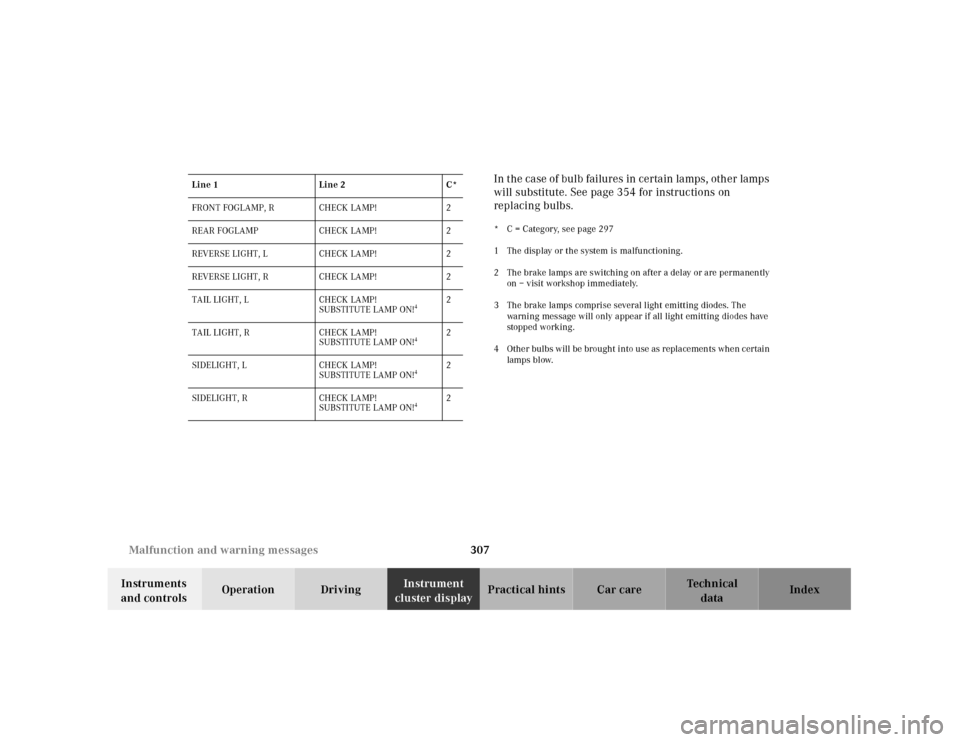
cluster displayPractical hints Car care IndexIn t he ca se of bul b failures in certa in la mps, oth er lamps
will substitute. See page 354 for instructions on
replacing bulbs.
* C = Category, see page 297
1 The display or the system is malfunctioning.
2 The brake lamps are switching on after a delay or are permanently
on – visit workshop immediately.
3 The brake lamps comprise several light emitting diodes. The
warning message will only appear if all light emitting diodes have
stopp ed working .
4 Other bulbs will be brought into use as replacements when certain
lamps blow. FRONT FOGLAMP, R CHECK LAMP! 2
REAR FOGLAMP CHECK LAMP! 2
REVERSE LIGHT, L CHECK LAMP! 2
REVERSE LIGHT, R CHECK LAMP! 2
TAIL LIGHT, L CHECK LAMP!
SUBSTITUTE LAMP ON!
4
2
TAIL LIGHT, R CHECK LAMP!
SUBSTITUTE LAMP ON!
4
2
SIDELIGHT, L CHECK LAMP!
SUBSTITUTE LAMP ON!
4
2
SIDELIGHT, R CHECK LAMP!
SUBSTITUTE LAMP ON!
4
2 Line 1 Line 2 C*
Page 314 of 424
308 Malfunction and warning messages
Te ch n ica l
data Instruments
and controlsOperation DrivingInstrument
cluster displayPractical hints Car care Index
LIGHT SENSOR
* C = Category, see page 297The headlamps will be switched on automatically if the
light sensor malfunctions.
The “LIGHT CIRCUIT HEADLAMP MODE” setting menu
can be set to “MANUAL” in the individual settings, see
page 142. It will then be possible to switch the
headlamps on and off using the exterior lamp switch.
See page 156 for notes on the exterior lamp switch. SEAT BELT SYSTEM
* C = Category, see page 297 Line 1 Line 2 C*
LIGHT SENSOR VISIT WORKSHOP! 2Line 1 Line 2 C*
SEAT BELT SYSTEM VISIT WORKSHOP! 2
Page 322 of 424
316 Malfunction and warning messages
Te ch n ica l
data Instruments
and controlsOperation DrivingInstrument
cluster displayPractical hints Car care Index
KEY
* C = Category, see page 297.
1 Key needs possibly to be replaced.
DOOR* C = Category, see page 297. Line 1 Line 2 C*
REPLACE KEY
1
VISIT WORKSHOP! 2
AUTOM. LIGHT ON REMOVE KEY! 1
P54.30-2245-21
Line 1 Line 2 C*
DOOR OPEN! 2
Page 331 of 424

325 Fuses
Te ch n ica l
data Instruments
and controlsOperation DrivingInstrument
cluster displayPractical hintsCar care Index Fuses
Most of your vehicle’s electrical components are fused
w ith safety fuses. Wit h th e exc eption of t he brake lig hts,
all individual lighting system components are
electronically fused. Before replacing a blown safety
fuse, determine the cause of the short circuit. Always
observe amperage and color of fuse.
The circuit for components is protected by a cycled
circuit breaker interrupted if too much current is being
drawn. The circuit closes automatically after a short
time; the circuit is broken again if the malfunction
reoccurs.
A l ways u s e a n ew f u s e f o r r e pl a c e m e nt . N eve r a t te mp t to
repair or bridge a blown fuse.
A fuse chart, spare fuses and a fuse extractor are located
in the vehicle tool kit in the luggage bowl under the
trunk floor. See page 335 for notes on the vehicle tool
kit.Fuse boxes in the engine compartment
1Fuse box in engine compartment, left-hand side
3Tabs
3
3
1
P54.15-2064-26
Page 349 of 424
343 Tires, Wheels
Te ch n ica l
data Instruments
and controlsOperation DrivingInstrument
cluster displayPractical hintsCar care Index 10. Clean contact surfaces of wheel and wheel hub.
Install spare wheel on wheel hub. Insert wheel bolts
and tighten them slightly.
To avoid paint damage, place wheel f lat against hub
and hold it there while installing first wheel bolt.
Unscrew the alignment bolt to install the last wheel
bolt.11. Lower vehicle. Remove jack and insert jack tube
cover.
P40.10-2264-26
P40.10-2263-26
Page 351 of 424

345 Tires, Wheels
Te ch n ica l
data Instruments
and controlsOperation DrivingInstrument
cluster displayPractical hintsCar care Index Tire inflation pressure
A table (see fuel filler f lap) lists the tire inflation
pressures specified for Mercedes-Benz recommended
tires as well as for the varying operating conditions.
Important!
Tire pressure changes by approx. 1.5 psi (0.1 bar) per
18°F (10°C) of air temperature change. Keep this in
mind when checking tire pressure inside a garage –
especially in the winter.
Example:
If garage temperature = approx. +68°F (+20°C) and
ambient temperature = approx. +32°F (0°C) then the
adjusted air pressure = specified air pressure +3 psi
(+0.2 bar).Tire pressures listed for light loads are minimum values
offering high driving comfort. Increased inflation
pressures for heavy loads produce favorable handling
characteristics with lighter loads and are perfectly
permissible. The ride of the vehicle, however, will
become somewhat harder.
Tire temperature and pressure increase with the vehicle
speed. Tire pressure should therefore only be checked
and corrected on cold tires. Correct tire pressure in
warm tires only if pressure has dropped below the
pressure listed in the table and the respective operating
conditions are taken into consideration.
An underinf lated tire due to a slow leak (e.g. due to a
nail in the tire) may cause damage such as tread
separation, bulging etc.. Regular tire pressure checks
(including the spare tire) at intervals of no more than
14 days are therefore essential.
If a tire constantly loses air, it should be inspected for
damage.
Page 356 of 424

350 Jump starting
Te ch n ica l
data Instruments
and controlsOperation DrivingInstrument
cluster displayPractical hintsCar care Index
Proceed as follows:
1. Position the vehicle with the charged battery so that
the jumper cables will reach, but never let the
vehicles touch. Make sure the jumper cables do not
have loose or missing insulation.
2. On both vehicles:
•Turn off engine and all lights and accessories,
except hazard warning flashers or work lights.
•Apply parking brake and shift selector lever to
position “P”.
Important!
3. Clamp one end of the first jumper cable to the
positive (+) terminal of the discharged battery and
the other end to the positive (+) terminal of the
charged battery. Make sure the cable clamps do not
touch any other metal parts.
4. Clamp one end of the second jumper cable to the
grounded negative (–) terminal of the charged
battery and the final connection to the negative (–)
under hood terminal of the disabled vehicle.Important!
5. Start engine of the vehicle with the charged battery
and run at high idle. Make sure the cables are not
on or near pulleys, fans, or other parts that move
when the engine is started. Allow the discharged
battery to charge for a few minutes. Start engine of
the disabled vehicle in the usual manner.
6. After the engine has started, remove jumper cables
by exactly reversing the above installation
sequence, starting with the last connection made
first. When removing each clamp, make sure that it
does not touch any other metal while the other end
is still attached.
Notes:
If engine does not run after several unsuccessful
starting attempts, have it checked at the nearest
authorized Mercedes-Benz Center.
Excessive unburned fuel may damage the catalytic
converter.
Page 360 of 424

354 Exterior lamps
Te ch n ica l
data Instruments
and controlsOperation DrivingInstrument
cluster displayPractical hintsCar care Index
Exterior lamps
Headlamp adjustment
Correct headlamp adjustment is extremely important.
Check and readjust headlamps at regular intervals and
when a bulb has been replaced.Replacing bulbs
Notes:
To prevent a possible electrical short circuit, switch off
lamp prior to replacing a bulb.
When replacing bulbs, install only 12 volt bulbs with
the specified watt rating.
When replacing halogen bulbs do not touch glass
portion of bulb with bare hands. Use plain paper or a
clean cloth.
If the newly installed bulb does not light up, switch the
lamp off and on again. If the bulb still does not light up,
have the system checked at an authorized
Mercedes-Benz Center.
Wa r n i n g !
Bulbs and bulb holders can be very hot. Allow the
lamp to cool down before changing a bulb.
Halogen lamps contain pressurized gas. A bulb can
explode if you:
• touch or move it when hot,
•drop the bulb,
• scratch the bulb.Wear eye and hand protection.
Wa r n i n g !
Because of high voltage in Xenon lamps, it is
dangerous to replace the bulb or repair the lamp
and its components. We recommend that you have
such work done by a qualified technician.