Page 28 of 424
25 Instruments and controls
Te ch n ica l
data Instruments
and controlsOperation DrivingInstrument
cluster displayPractical hints Car care Index 12Ashtray, see page 196
Lighter, see page 198
13Start-/Stop button
Starter switch for KEYLESS-GO only, see page 224
14Automatic transmission, see page 22915AIRBAG OFF indicator lamp, see page 296
16Distronic (DTR) – switch for distance notification
function, see page 265
17Distronic (DTR) – thumbwheel for setting distance,
seepage265
Page 36 of 424

33 Central locking system
Te ch n ica l
data Instruments
and controlsOperationDrivingInstrument
cluster displayPractical hints Car care Index General notes on the central locking system
If the electronic key is inserted in the starter switch, the
vehicle cannot be locked or unlocked with the remote
control.
If the vehicle cannot be locked or unlocked:
•Aim transmitter eye at a receiver on either door
handle. Check the batteries of the electronic main
key, see page 363, or synchronize the remote
control, see page 365.
•Vehicles with KEYLESS-GO only:
A KEYLESS-GO-card must be recognized by the
system as being outside the vehicle to enable the
vehicle to be locked or unlocked (maximum distance
between card and doors or trunk is approx. 3 ft. (1
m). Check the location of the KEYLESS-GO-card, see
page 38. Check the batteries of the KEYLESS-GO-
card, see page 366. The trunk lid will open
automatically if a KEYLESS-GO card is detected in
the trunk, see page 38.Note:
If neither the remote control nor KEYLESS-GO system
functions, use the mechanical key to unlock or lock the
vehicle. To start engine, insert the electronic key in the
starter switch. There could be a slight delay until the
electronic key can be turned in the starter switch.
Important!
When unlocking the driver’s door with the mechanical
key, the exterior lamps will flash and the alarm will
sound.
To cancel the alarm, insert the electronic key in the
starter switch, or press buttonŒ or‹ on the
electronic main key; or with the optional KEYLESS-GO-
system, when carrying a KEYLESS-GO-card, by grasping
a door handle or pressing the start-/stop button on the
gear selector lever.
Page 75 of 424

72 Seats
Te ch n ica l
data Instruments
and controlsOperationDrivingInstrument
cluster displayPractical hints Car care Index
Backrest
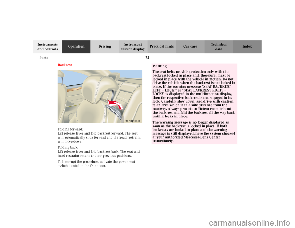
Folding forward:
Lift release lever and fold backrest forward. The seat
will automatically slide forward and the head restraint
will move down.
Folding back:
Lift release lever and fold backrest back. The seat and
head restraint return to their previous positions.
To interrupt the procedure, activate the power seat
switch located in the front door.
Wa r n i n g !
The seat belts provide protection only with the
backrest locked in place and, therefore, must be
locked in place with the vehicle in motion. Do not
drive the vehicle when the backrest is not locked in
place. If the warning message “SEAT BACKREST
LEFT – LOCK!” or “SEAT BACKREST RIGHT –
LOCK!” is displayed in the multifunction display,
then the respective backrest is not engaged in its
lock. Carefully slow down, and drive with caution
to an area which is in a safe distance from the
roadway. Always provide sufficient room behind
the backrest and fold the backrest all the way back
until it locks in place.The warning message is no longer displayed as
soon as the backrest is locked in place. If both
backrests are locked in place and the warning
message is still displayed, have the system checked
at your authorized Mercedes-Benz Center
immediately.
Page 100 of 424

97 Restraint systems
Te ch n ica l
data Instruments
and controlsOperationDrivingInstrument
cluster displayPractical hints Car care Index Your vehicle was originally equipped with airbags
which are designed to activate in certain impacts
exceeding a preset threshold to reduce the potential
and severity of injury. It is important to your safety
and that of your passenger that you replace deployed
airbags and repair any malfunctioning airbags to
ensure the vehicle will continue to provide crash
protection for occupants.
Wa r n i n g !
To reduce the risk of injury when the front airbags
inflate, it is very important for the driver and front
passenger to always be in a properly seated
position and to wear your seat belt.For maximum protection in the event of a collision
always be in normal seated position w ith your back
against the backrest. Fasten your seat belt and
ensure that it is properly positioned on your body.Since the airbag inflates with considerable speed
and force, a proper seating and hands on steering
wheel position will help to keep you at a safe
distance from the airbag. Occupants who are
unbelted, out of position or too close to the airbag
can be seriously injured by an airbag as it inflates
with great force in the blink of an eye:
• Sit properly belted in an upright position with
your back against the backrest.• Adjust the driver seat as far as possible
rearward, still permitting proper operation of
vehicle controls. The distance from the center
of the driver’s breastbone to the center of the
airbag cover on the steering wheel must be at
least ten inches (25 cm) or more. You should be
able to accomplish this by a combination of
adjustments to the seat and steering wheel. If
you have any problems, please see your
authorized Mercedes-Benz Center.• Do not lean wi th you r head or chest close to th e
steering wheel or dashboard.• Keep hands on the outside of steering wheel
rim. Placing hands and arms inside the rim
can increase the risk and potential severity of
hand/arm injury when driver front airbag
inflates.• Adjust the front passenger seat as far as
possible rearward from the dashboard when
the seat is occupied.
Page 118 of 424

115 Instrument cluster
Te ch n ica l
data Instruments
and controlsOperationDrivingInstrument
cluster displayPractical hints Car care Index 1Knob for instrument cluster illumination,
s e e p a g e 116
2Engine malfunction indicator lamp, see page 290
3Brake fluid low or parking brake engaged,
see page 301
4Supplemental restraint system (SRS) malfunction
indicator lamp, see page 293
5Coolant temperature gauge, see page 117
6Outside temperature indicator, see page 117
7Fuel gauge with reserve warning lamp, see page 293
8Left turn signal indicator lamp, see combination
switch on page 160
9Speedometer, see page 118
10Electronic stability program (ESP) warning lamp,
system is adjusting to road conditions, see page 295
11Distance warning lamp – vehicles with Distronic
(DTR), distance to the vehicle ahead is insufficient,
see page 264 and page 295.12Multifunction display, see page 120
Instrument cluster display, see page 297
13Trip odometer, see page 119 and 124
14Main odometer, see page 124
15Right turn signal indicator lamp, see combination
switch on page 160
16Tachometer, see page 119
17Gear range indicator display, see selector lever
positions on page 232
18Digital clock
To set the time, see COMAND operator’s manual
19Antilock brake system (ABS) malfunction indicator
lamp, see page 294
20High beam headlamp indicator,
see exterior lamp switch, page 156, and
combination switch, page 160
21Fasten seat belts, see page 296
22Reset buttonJ, s e e p a g e s 116 , 119
Activating the instrument cluster display
The instrument cluster is activated by:•Opening the door
1.
•Pressing button Jon the instrument cluster
1.
Page 136 of 424
133 Multifunction steering wheel, multifunction display
Te ch n ica l
data Instruments
and controlsOperationDrivingInstrument
cluster displayPractical hints Car care Index Distronic (DTR) 1Distronic (DTR) is deactivated. The actual
distance (4) and the should-be distance (5) to the
vehicle in front (3) are displayed.
2Distronic (DTR) is activated.
The message “DTR OFF” appears for five seconds
when Distronic is being deactivated.
3Vehicle ahead. Only appears if a vehicle is detected
ahead.
4Actual distance to vehicle ahead.
5Should-be distance to vehicle ahead.
6Own vehicle.
Press theè or ÿbutton repeatedly until the
required system is displayed.
Distronic (DTR), see page 253.
Pressing theè or ÿbutton displays the next or
previous system.
Page 137 of 424
134 Multifunction steering wheel, multifunction display
Te ch n ica l
data Instruments
and controlsOperationDrivingInstrument
cluster displayPractical hints Car care Index
Trip computer 1“AFTER START” — short distance memory
2“AFTER RESET” — long distance memory
3Fuel tank contents and estimated range remaining
4Distance covered “AFTER START” or
“AFTER RESET”
5Elapsed time “AFTER START” or “AFTER RESET”
6Average speed “AFTER START” or “AFTER RESET”
7Average fuel consumption “AFTER START” or
“AFTER RESET”
Press the buttonè orÿ repeatedly until the
display (1, 2 or 3) appears.
Press thej or k button until the “AFTER START”
short distance memory (1), the “AFTER RESET” long
distance memory (2) or fuel tank contents and
estimated range remaining indicator (3) appears.
Pressing the è or ÿ button displays the next or
previous system.
Note:
The most recently selected display (1, 2 or 3) always
appears the next time the trip computer is called up.
Page 138 of 424
135 Multifunction steering wheel, multifunction display
Te ch n ica l
data Instruments
and controlsOperationDrivingInstrument
cluster displayPractical hints Car care Index Transferri ng values from the previou s journey to th e
“AFTER START” short distance memory (1):
T h e “ AF T E R START ” d i s pl ay w il l f l a s h u n t il a d i st a n c e of
approximately 1 mile (1.6 km) has been covered or two
minutes have elapsed since the engine was restarted.
During this period you can incorporate the values for
the previous journey by pressing button Jin the
instrument cluster.To reset the short “AFTER START” (1) or long
“AFTER RESET” distance memory (2):
Call up the relevant display (1 or 2) using thej or
kbutton and press the Jbutton in the
instrument cluster until the values are reset to “0”.