2001 MERCEDES-BENZ CL500 clock
[x] Cancel search: clockPage 118 of 424

115 Instrument cluster
Te ch n ica l
data Instruments
and controlsOperationDrivingInstrument
cluster displayPractical hints Car care Index 1Knob for instrument cluster illumination,
s e e p a g e 116
2Engine malfunction indicator lamp, see page 290
3Brake fluid low or parking brake engaged,
see page 301
4Supplemental restraint system (SRS) malfunction
indicator lamp, see page 293
5Coolant temperature gauge, see page 117
6Outside temperature indicator, see page 117
7Fuel gauge with reserve warning lamp, see page 293
8Left turn signal indicator lamp, see combination
switch on page 160
9Speedometer, see page 118
10Electronic stability program (ESP) warning lamp,
system is adjusting to road conditions, see page 295
11Distance warning lamp – vehicles with Distronic
(DTR), distance to the vehicle ahead is insufficient,
see page 264 and page 295.12Multifunction display, see page 120
Instrument cluster display, see page 297
13Trip odometer, see page 119 and 124
14Main odometer, see page 124
15Right turn signal indicator lamp, see combination
switch on page 160
16Tachometer, see page 119
17Gear range indicator display, see selector lever
positions on page 232
18Digital clock
To set the time, see COMAND operator’s manual
19Antilock brake system (ABS) malfunction indicator
lamp, see page 294
20High beam headlamp indicator,
see exterior lamp switch, page 156, and
combination switch, page 160
21Fasten seat belts, see page 296
22Reset buttonJ, s e e p a g e s 116 , 119
Activating the instrument cluster display
The instrument cluster is activated by:•Opening the door
1.
•Pressing button Jon the instrument cluster
1.
Page 119 of 424

116 Instrument cluster
Te ch n ica l
data Instruments
and controlsOperationDrivingInstrument
cluster displayPractical hints Car care Index
•Turning the electronic key in starter switch to
position 1 or 2.
•Switching on the exterior lamps.
1 The instrument cluster is activated for approx. 30 seconds.Instrument cluster illumination
The instrument cluster illumination is dimmed or
brightened automatically to suit daylight lighting
conditions.
The instrument cluster illumination will also be
adjusted when the vehicle’s exterior lamps are
switched on.Display illumination, changing basic settings for driving
at dusk or in darkness:
Press adjusting knob (1) – the knob will pop out.
Rotate adjusting knob (1) clockwise – instrument lamp
intensity increases.
Rotate adjusting knob (1) counterclockwise –
instrument lamp intensity decreases.
Push knob back into panel.
Note:
It is not possible to select a basic brightness setting in
daylight – the intensity is adjusted automatically.
Page 144 of 424

141 Multifunction steering wheel, multifunction display
Te ch n ica l
data Instruments
and controlsOperationDrivingInstrument
cluster displayPractical hints Car care Index 1Preliminary display of the individual settings
2“SETTINGS” – the menu “INSTRUMENT CLUSTER”
can be called up in this option menu.
3Selection marker
Pressing buttonæ orç on the multifunction
steering wheel controls the selection marker.
4“TEMP. INDICATOR” – the unit set is displayed in
the outside temperature display, in the instrument
cluster and in the automatic air conditioner display.
5“SPEEDOMETER” – the unit set is displayed in the
multifunction display
For setting clock, see separate COMAND
operator’s manual.
6“TEXT” – sets the language used in the
multifunction display
7Returning the setting menu “INSTRUMENT
CLUSTER” to the factory setting.
8Acknowledgment
Press theè or ÿbutton repeatedly until the
individual setting preliminary display (1) appears.
Press thej or kbutton until the setting menu
“SETTINGS” (2) is displayed.Press buttonæ orç until the menu
“INSTRUMENT CLUSTER” is selected by the selection
marker (3).
Press thej or kbutton until the required
display (4 to 6) is displayed. Pressing theæ orç
button controls the selection marker. The settings made
are stored and applied immediately.
The individual setting preliminary display (1) will
appear again after you have run through all the setting
menus. Pressing theè or ÿbutton displays the
next or previous system.
To return menu “INSTRUMENT CLUSTER” (4 to 6) to
its factory setting:
•Call up menu (4 to 6).
•Press the Jbutton in the instrument cluster for
approximately 3 seconds. Display (7) will appear.
•Press the Jbutton once more. The menu
“INSTR. CLUSTER” is reset to factory settings,
acknowledged by display (8).
The individual setting display “SETTINGS” (2) will
appear if you do not press the Jbutton within
about 5 seconds. The setting menus will not be
reset.
Page 232 of 424

227 Starting and turning off the engine
Te ch n ica l
data Instruments
and controlsOperationDrivingInstrument
cluster displayPractical hints Car care Index Starting and turning off the engine
Before starting
Ensure that parking brake is engaged and that selector
lever is in position “P” or “N”.
Starting
Important!
In areas where temperatures frequently drop below -4°F
(-20°C) we recommend that an engine block heater be
installed. Your authorized Mercedes-Benz Center will
advise you on this subject.
Starting the engine with electronic key:
Do not depress accelerator.
Turn electronic key in starter switch to position 2.
Briefly turn electronic key in starter switch clockwise to
the stop and release. The starter will engage until the
engine is running.
If engine will not run, and the starting procedure stops,
turn electronic key completely to the left and repeat
starting the engine.After several unsuccessful attempts, have the system
checked at the nearest authorized Mercedes-Benz
Center.
Important!
Due to the installed starter non-repeat feature, the
electronic key must be turned completely to the left
before attempting to start the engine again.
Starting the engine with KEYLESS-GO:
Note:
For improved recognition of the chip card the doors
should be closed when pressing the start-/stop button.
Depress brake pedal during the starting procedure.
Briefly press start-/stop button on gear selector lever.
The starter will engage until the engine is running.
If engine will not run, and the starting procedure stops,
press start-/stop button on gear selector lever and repeat
starting the engine.
After several unsuccessful attempts, have the system
checked at the nearest authorized Mercedes-Benz
Center.
Page 341 of 424

335 Spare wheel
Te ch n ica l
data Instruments
and controlsOperation DrivingInstrument
cluster displayPractical hintsCar care Index Spare wheel, vehicle tools, storage compartment
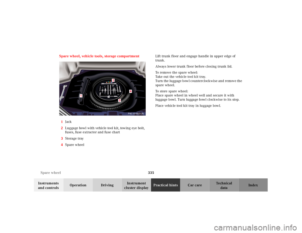
1Jack
2Luggage bowl with vehicle tool kit, towing eye bolt,
fuses, fuse extractor and fuse chart
3Storage tray
4Spare wheel Lift trunk floor and engage handle in upper edge of
trunk.
Always lower trunk f loor before closing trunk lid.
To remove the spare wheel:
Take out the vehicle tool kit tray.
T u rn t h e l u g g a g e b ow l c o u n te r c l ock w i s e a n d r e m ov e t h e
spare wheel.
To store spare wheel:
Place spare wheel in wheel well and secure it with
luggage bowl. Turn luggage bowl clockwise to its stop.
Place vehicle tool kit tray in luggage bowl.
P40.10-0523-26
1
4
3
2
Page 342 of 424

336 Jack
Te ch n ica l
data Instruments
and controlsOperation DrivingInstrument
cluster displayPractical hintsCar care Index
Jack
To prepare the jack for use:
Remove the jack from the spare wheel well under the
trunk floor, push the crank handle up and turn
clockwise until it engages (operational position).Storing the jack in the trunk:
Retract the jack arm to the base of the jack, push the
crank handle up and turn counterclockwise to the end
of the stop (storage position).
P58.10-2001-26
Wa r n i n g !
The jack is designed exclusively for jacking up the
veh icle at th e jack tu bes bu ilt into eit her side of th e
vehicle. To help avoid personal injury, use the jack
only to lift the vehicle during a wheel change.
Never get beneath the vehicle while it is supported
by t he jack. Keep hands and feet away from th e area
under the lifted vehicle. Always firmly set parking
brake and block wheels before raising vehicle with
jack.Do not disengage parki ng brake wh ile th e vehi cle i s
raised. Be certain that the jack is always vertical
when in use, especially on hills. Always try to use
the jack on level surface. Be sure that the jack arm
is fully inserted in the jack tube. Always lower the
vehicle onto sufficient capacity jackstands before
working under the vehicle.
Page 353 of 424

347 Battery
Te ch n ica l
data Instruments
and controlsOperation DrivingInstrument
cluster displayPractical hintsCar care Index The maintenance-free battery is located in the trunk
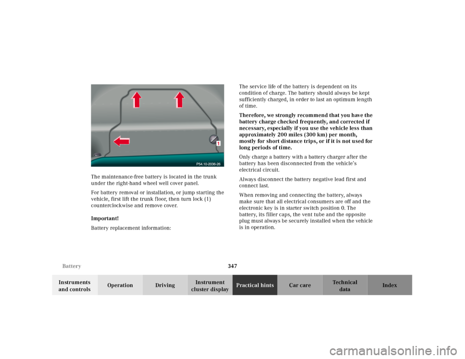
under the right-hand wheel well cover panel.
For battery removal or installation, or jump starting the
vehicle, first lift the trunk f loor, then turn lock (1)
counterclockwise and remove cover.
Important!
Battery replacement information:The service life of the battery is dependent on its
condition of charge. The battery should always be kept
sufficiently charged, in order to last an optimum length
of time.
Therefore, we strongly recommend that you have the
battery charge checked frequently, and corrected if
necessary, especially if you use the vehicle less than
approximately 200 miles (300 km) per month,
mostly for sh ort di stance trips, or if it is not u sed for
long periods of time.
Only charge a battery with a battery charger after the
battery has been disconnected from the vehicle’s
electrical circuit.
Always disconnect the battery negative lead first and
connect last.
When removing and connecting the battery, always
make sure that all electrical consumers are off and the
electronic key is in starter switch position 0. The
battery, its filler caps, the vent tube and the opposite
plug must always be securely installed when the vehicle
is in operation.
Page 354 of 424

348 Battery
Te ch n ica l
data Instruments
and controlsOperation DrivingInstrument
cluster displayPractical hintsCar care Index
While the engine is running the battery terminal clamps
must not be loosened or detached, otherwise the
generator and other electronic components would be
damaged.
Note:
After reconnecting the battery also set the clock (see
COMAND operator’s manual) resynchronize the express
feature of the power windows (see page 180), the
sliding/pop-up roof (see page 183), and the electronic
stability program (see page 272).Battery recycling
Batteries contain materials that can harm the
environment with improper disposal.
Large 12 Volt storage batteries contain lead.
Recycling of batteries is the preferred method of
disposal.
Many states require sellers of batteries to accept old
batteries for recycling.