2001 MERCEDES-BENZ C320 spare tire
[x] Cancel search: spare tirePage 8 of 381

ContentsWheels .............................................306
Tire replacement ........................306
Rotating wheels ..........................307
Spare wheel ....................................308
Changing wheels ...........................309
Tire inflation pressure .................. 315
Battery ............................................. 316
Jump starting .................................. 318
Towing the vehicle ......................... 321
Transmission selector lever,
manually unlocking ...................325
Exterior lamps ................................326
Replacing bulbs ..........................326
Trunk lamp ..................................... 331
Changing batteries in the electronic
main key .....................................332Synchronizing remote
control ......................................... 334
Emergency engine shut-down ..... 334
Fuel filler flap, manual release ... 335
Replacing wiper blade insert ...... 337
Roof rack ......................................... 338
Vehicle careCleaning and care of
the vehicle ................................. 340
Power washer ............................. 341
Tar stains .................................... 341
Paintwork, painted body
components ................................ 341
Engine cleaning ......................... 342
Vehicle washing ......................... 342Ornamental moldings ................343
Headlamps, taillamps, turn signal
lenses ...........................................343
Window cleaning .......................343
Wiper blade .................................343
Light alloy wheels ......................344
Instrument cluster .....................344
Steering wheel and gear selector
lever ..............................................344
Cup holder ...................................344
Seat belts .....................................345
Headliner and shelf below rear
window ........................................345
Leather upholstery .....................345
Hard plastic trim items .............345
Plastic and rubber parts ............345
Page 9 of 381

Contents
Technical dataSpare parts service ........................348
Warranty coverage .........................348
Identification labels .......................349
Layout of poly-V-belt drive ............350
Technical data ................................ 351
Fuels, coolants, lubricants etc. -
capacities ...................................355
Engine oils ......................................357Engine oil additives ...................... 357
Air conditioner refrigerant .......... 357
Brake fluid ...................................... 357
Premium unleaded gasoline ........ 358
Fuel requirements ........................ 358
Gasoline additives ......................... 359
Coolants .......................................... 359
Consumer information ................. 361
Uniform tire quality grading ....... 361
IndexIndex .................................................364
Page 232 of 381
223 Tele Aid
Te ch n i c a l
data Instruments
and controlsOperationDrivingInstrument
cluster displayPractical hints Car care Index Roadside Assistance button
Located below the center armrest cover is the Roadside
Assistance button. Pressing and holding the
button (for longer than 2 seconds) will initiate a call to a
Mercedes-Benz Roadside Assistance dispatcher. The
button will flash while the call is in progress. The
Tele Aid system will transmit data generating the
vehicle identification number, model, color and location
(subject to availability of cellular and GPS signals).A voice connection between the Roadside Assistance
dispatcher and the occupants of the vehicle will be
established. The nature of the need for assistance can
then be described. Sign and Drive services (jump start, a
few gallons of fuel or the replacement of a flat tire with
the vehicle spare tire) are available.
If the vehicle requires more than Sign and Drive
services, the Mercedes-Benz Roadside assistance
dispatcher will either dispatch a qualified
Mercedes-Benz technician or arrange to tow your
vehicle to the nearest Mercedes-Benz Center.
For other than Sign and Drive services, labor and / or
towing charges may apply. Refer to the Roadside
Assistance manual for more information.
Notes:
The indicator lamp in the Roadside Assistance
button remains illuminated in red for
approximately 5 seconds during the system self-check
after turning electronic key in starter switch to
position 2 (together with the “SOS” button and the
Information button¡).
See system self-check on page 220 when the indicator
lamp does not light up in red or stays on longer than
approximately 5 seconds.
Wa r n i n g !
If you feel at any way in jeopardy when in the
vehicle (e.g. smoke or fire in the vehicle, vehicle in
a dangerous road location), please do not wait for
voice contact after you have pressed the emergency
button. Carefully leave the vehicle and move to a
safe location. The Response Center will
automatically contact local emergency officials
with the vehicle’s approximate location if they
receive an “SOS” signal and cannot make voice
contact with the vehicle occupants.
Page 270 of 381
261 Driving systems
Te ch n i c a l
data Instruments
and controlsOperationDrivingInstrument
cluster displayPractical hints Car care Index Notes:
The yellow ESP warning lampv in the speedometer
dial comes on with the electronic key in starter switch
position 2. It should go out with the engine running.
If the ESP warning message is displayed, a malfunction
has been detected in the system. Pressing the
accelerator pedal will require greater effort. Only partial
engine output will be available.
Have the ESP checked at your authorized
Mercedes-Benz Center as soon as possible.
For ESP warning message, see page 273.
With the ABS malfunctioning, the ESP is also switched
off.
Driving the vehicle with varied size tires will cause the
wheels to rotate at different speeds, therefore the ESP
may activate (yellow ESP warning lamp in speedometer
d ial com es on ). For t his reas on, all wheels, in cludin g t he
spare wheel, must have the same tire size. When testing the parking brake on a brake test
dynamometer, the engine must be shut off. Otherwise,
the ESP will immediately be engaged and will apply the
rear wheel brakes.
In winter operation, the maximum effectiveness of the
ESP is only achieved with Mercedes-Benz recommended
M+S rated radial-ply tires and / or snow chains.
Synchronizing ESP
If the power supply was interrupted (battery
disconnected or empty), the ESP warning message may
be displayed with the engine running.
Turn steering wheel completely to the left and then to
the right. The ESP warning message should go out.
Page 302 of 381
293 Contents - Practical hints
Te ch n i c a l
data Instruments
and controlsOperation DrivingInstrument
cluster displayPractical hintsCar care Index
Practical hintsFirst aid kit .....................................294
Stowing things in the vehicle ......294
Fuses ................................................295
Hood .................................................297
Checking engine oil level .............300
Automatic transmission fluid
level ............................................. 301
Coolant level ................................... 301
Adding coolant ...........................302
Windshield and headlamp washer
system .........................................302Spare wheel, vehicle tools, storage
compartment ............................. 304
Vehicle jack .................................... 305
Wheels ............................................ 306
Tire replacement ....................... 306
Rotating wheels ......................... 307
Spare wheel .................................... 308
Changing wheels ........................... 309
Tire inflation pressure .................. 315
Battery .............................................. 316
Jump starting .................................. 318
Towing the vehicle ........................ 321
Transmission selector lever,
manually unlocking .................. 325Exterior lamps ................................326
Replacing bulbs ..........................326
Trunk lamp ..................................... 331
Changing batteries in the electronic
main key .....................................332
Synchronizing remote
control ..........................................334
Emergency engine shut-down .....334
Fuel filler flap, manual release ...335
Replacing wiper blade insert .......337
Roof rack .........................................338
Page 317 of 381

308 Tires, Wheels
Te ch n i c a l
data Instruments
and controlsOperation DrivingInstrument
cluster displayPractical hintsCar care Index
Spare wheel
Important!
The spare wheel rim is mounted with a full size tire of
the same type as on the vehicle, and is fully functional.
However, that spare wheel rim is weight optimized and
has a limited service life of 12 000 miles (20 000 km)
use before a standard wheel rim must replace it.
In the case of a flat tire, you may temporarily use the
spare wheel.
Do not operate vehicle with more than one spare wheel
mounted.Spare wheel
The spare wheel rim size is 7 J x 16 H2
(C 240 Canada only - steel rims 6
1/2 J x 16 H2).
In the case of a flat tire or breakdown, you may
temporarily use the spare wheel, while observing the
following restrictions:
•Do not exceed vehicle speed of 50 mph (80 km / h).
•Drive to the nearest repair facility to have the flat
tire repaired or replaced as appropriate.
•Do not operate vehicle with more than one spare
wheel mounted.
For additional information, refer to page 352.
Wa r n i n g !
The spare wheel rim is for temporary use only. Use
for over a total of 12 000 miles (20 000 km)
(aggregate of all uses) may cause wheel rim failure
leading to an accident and possible injuries.
Page 318 of 381
309 Tires, Wheels
Te ch n i c a l
data Instruments
and controlsOperation DrivingInstrument
cluster displayPractical hintsCar care Index Changing wheels
Wa r n i n g !
The spare wheel rim is for temporary use only. Use
for over a total of 12 000 miles (20 000 km) may
cause wheel rim failure leading to an accident and
possible injuries. The dimensions of the spare wheel are different
from those of road wheels. As a result, the vehicle
handling characteristics change when driving with
a mounted spare wheel.The spare wheel should only be used temporarily,
and replaced with a regular road wheel as quickly
as possible.
Wa r n i n g !
The jack is designed exclusively for jacking up the
vehic l e at t he j a ck ta ke-up brackets bui l t in to ei ther
side of the vehicle. To help avoid personal injury,
use the jack only to lift the vehicle during a wheel
change. Never get beneath the vehicle while it is
supported by the jack. Keep hands and feet away
from the area under the lifted vehicle. Always
firmly set parking brake and block wheels before
raising vehicle with jack.Do not d i sen ga ge park in g b ra ke whi l e the vehic l e is
raised. Be certain that the jack is always vertical
when in use, especially on hills. Always try to use
the jack on level surface. Be sure that the jack arm
is fully seated in the jack take-up bracket. Always
lower the vehicle onto sufficient capacity
jackstands before working under the vehicle.
Page 322 of 381
313 Tires, Wheels
Te ch n i c a l
data Instruments
and controlsOperation DrivingInstrument
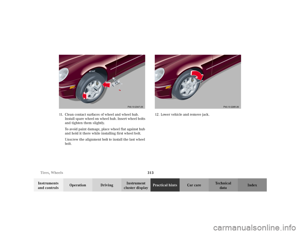
cluster displayPractical hintsCar care Index 11. Clean contact surfaces of wheel and wheel hub.
Install spare wheel on wheel hub. Insert wheel bolts
and tighten them slightly.
To avoid paint damage, place wheel flat against hub
and hold it there while installing first wheel bolt.
Unscrew the alignment bolt to install the last wheel
bolt.12. Lower vehicle and remove jack.
P40.10-2347-26
P40.10-2285-26