Page 281 of 381
272 Malfunction and indicator lamps
Te ch n i c a l
data Instruments
and controlsOperation DrivingInstrument
cluster displayPractical hints Car care Index
ABS malfunction indicator lamp
The ABS malfunction indicator lamp in the
instrument cluster comes on with the
electronic key in starter switch position 2
and should go out with the engine running.
When the ABS malfunction indicator lamp symbol and
warning in the instrument cluster remains illuminated
while the engine is running, it indicates that the ABS
has detected a malfunction and has switched off. In this
case, the brake system functions in the usual manner,
but without antilock assistance.
A malfunctioning ABS control unit can possibly affect
the operation of other systems (e.g. Navigation,
Automatic transmission). Be guided accordingly with
respect to the use of those systems and have the system
checked at your authorized Mercedes-Benz Center as
soon as possible.With the ABS malfunctioning, the BAS and ESP are also
switched off. The malfunction indicator lamps and
malfunction messages in the multifunction display
come on with the engine running.
If the charging voltage falls below 10 volts, the
malfunction indicator lamp comes on and the ABS is
switched of f. When the voltage is above this value again,
the malfunction indicator lamp should go out and the
ABS is operational.
Have the system checked at your authorized
Mercedes-Benz Center as soon as possible.
See page 258 for notes on antilock brake system (ABS).
ABS
Page 282 of 381
273 Malfunction and indicator lamps
Te ch n i c a l
data Instruments
and controlsOperation DrivingInstrument
cluster displayPractical hints Car care Index Electronic stability program (ESP) — warning lamp
The yellow ESP warning lamp in the
speedometer dial comes on with the
electronic key in starter switch position 2.
It should go out with engine running.
If the ESP malfunction indicator lamp remains
illuminated with the engine running, a malfunction has
been detected in the system. Pressing the accelerator
pedal will require greater effort. Only partial engine
output will be available.
See elec tr on ic stability p rogram (ESP ) on p age 26 0 if t he
warning lamp lights up or flashes when the vehicle is
moving.
Seat belt nonusage warning lamp
With the electronic key in starter switch
position 2, the seat belt nonusage warning
lamp comes on, and a warning sounds for a
short time if the drivers seat belt is not fastened.
After starting the engine, the seat belt nonusage
warning lamp blinks for a brief period to remind the
driver and passengers to fasten seat belts.Malfunction and indicator lamp in the center
console
AIRBAG OFF indicator lamp
The ü indicator lamp will light up for approximately
6 seconds when you turn the electronic key in starter
switch to position 1 or 2.
It does not light up if there is a fault in the system.
The ü indicator lamp stays lit as long as a
Baby Smart
TM child seat is properly installed on the
front passenger seat. It indicates that the front
passenger airbag is switched off.
See page 62 for BabySmart
TM airbag and its deactivation
system.
Baby Smart
TM is a trademark of Siemens Automotive Corp.
Page 293 of 381
284 Malfunction and warning messages
Te ch n i c a l
data Instruments
and controlsOperation DrivingInstrument
cluster displayPractical hints Car care Index
LIGHTING SYSTEM
Line 1 Line 2 C*
LOW BEAM,L CHECK LAMP! 2
LOW BEAM,R CHECK LAMP! 2
DISPLAY DEFECTIVE VISIT WORKSHOP!
1
2
TURN SIGNAL, L CHECK LAMP! 2
TURN SIGNAL, R CHECK LAMP! 2
L. TURN SIG. RFLECTR CHECK LAMP! 2
R. TURN SIG. RFLECTR CHECK LAMP! 2
TURN SIGNAL F, L CHECK LAMP! 2
TURN SIGNAL F, R CHECK LAMP! 2
BRAKE LIGHT
2
VISIT WORKSHOP! 2
BRAKE LIGHT, L
3
CHECK LAMP! 2
BRAKE LIGHT, R
3
CHECK LAMP! 2
3RD STOP LAMP
3
CHECK LAMP! 2
HIGH BEAM, L CHECK LAMP! 2
HIGH BEAM, R CHECK LAMP! 2
LICENSE PLATE L, L CHECK LAMP! 2
LICENSE PLATE L, R CHECK LAMP! 2
LIGHTS SWITCH OFF LIGHTS! 1
AUTOM. LIGHT ON REMOVE KEY! 1
FRONT FOGLAMP, L CHECK LAMP! 2
FRONT FOGLAMP, R CHECK LAMP! 2
REAR FOGLAMP CHECK LAMP! 2 Line 1 Line 2 C*
Page 299 of 381
290 Malfunction and warning messages
Te ch n i c a l
data Instruments
and controlsOperation DrivingInstrument
cluster displayPractical hints Car care Index
RESTRAINT SYSTEM
* C = Category, see page 274.See page 55 for notes on the seat belts, and page 65 for
notes on the airbags.KEY
* C = Category, see page 274.
1 Key needs possibly to be replaced. Line 1 Line 2 C*
RESTRAINT SYSTEM VISIT WORKSHOP! 1Line 1 Line 2 C*
REPLACE KEY
1
VISIT WORKSHOP! 2
AUTOM. LIGHT ON REMOVE KEY! 1
Page 302 of 381
293 Contents - Practical hints
Te ch n i c a l
data Instruments
and controlsOperation DrivingInstrument
cluster displayPractical hintsCar care Index
Practical hintsFirst aid kit .....................................294
Stowing things in the vehicle ......294
Fuses ................................................295
Hood .................................................297
Checking engine oil level .............300
Automatic transmission fluid
level ............................................. 301
Coolant level ................................... 301
Adding coolant ...........................302
Windshield and headlamp washer
system .........................................302Spare wheel, vehicle tools, storage
compartment ............................. 304
Vehicle jack .................................... 305
Wheels ............................................ 306
Tire replacement ....................... 306
Rotating wheels ......................... 307
Spare wheel .................................... 308
Changing wheels ........................... 309
Tire inflation pressure .................. 315
Battery .............................................. 316
Jump starting .................................. 318
Towing the vehicle ........................ 321
Transmission selector lever,
manually unlocking .................. 325Exterior lamps ................................326
Replacing bulbs ..........................326
Trunk lamp ..................................... 331
Changing batteries in the electronic
main key .....................................332
Synchronizing remote
control ..........................................334
Emergency engine shut-down .....334
Fuel filler flap, manual release ...335
Replacing wiper blade insert .......337
Roof rack .........................................338
Page 326 of 381
317 Battery
Te ch n i c a l
data Instruments
and controlsOperation DrivingInstrument
cluster displayPractical hintsCar care Index Therefore, we strongly recommend that you have the
battery charge checked frequently, and corrected if
necessary, especially if you use the vehicle less than
approximately 200 miles (300 km) per month,
mostly for short distance trips, or if it is not used for
long periods of time.
Only charge a battery with a battery charger after the
battery has been disconnected from the vehicle’s
electrical circuit.
Always disconnect the battery negative lead first and
connect last.
When removing and connecting the battery, always
make sure that all electrical consumers are off and the
electronic key is in starter switch position 0. The
battery, its filler caps, the vent tube and the opposite
plug must always be securely installed when the vehicle
is in operation.
While the engine is running the battery terminal clamps
must not be loosened or detached, otherwise the
generator and other electronic components would be
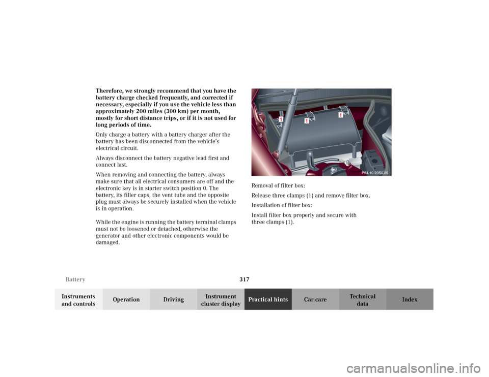
damaged.Removal of filter box:
Release three clamps (1) and remove filter box.
Installation of filter box:
Install filter box properly and secure with
three clamps (1).
Page 330 of 381
321 Towing the vehicle
Te ch n i c a l
data Instruments
and controlsOperation DrivingInstrument
cluster displayPractical hintsCar care Index Note:
If engine does not run after several unsuccessful
starting attempts, have it checked at the nearest
authorized Mercedes-Benz Center.
Excessive unburned fuel may damage the catalytic
converter.Towing the vehicle
Wa r n i n g !
Prior to towing the vehicle with all wheels on the
ground, make certain that the electronic key is in
starter switch position 2.If the electronic key is left in the starter switch
position 0 for an extended period of time, it can no
longer be turned in the switch. In this case, the
steering is locked. To unlock, remove electronic key
from starter switch and reinsert.
Page 331 of 381
322 Towing the vehicle
Te ch n i c a l
data Instruments
and controlsOperation DrivingInstrument
cluster displayPractical hintsCar care Index
Important!
When towing the vehicle, please, note the following:
With the automatic central locking activated and the
electronic key in starter switch position 2, the vehicle
doors lock if the left front wheel as well as the right rear
wheel are turning at vehicle speeds of approximately
9 mph (15 km / h) or more.
To prevent the vehicle door locks from locking,
deactivate the automatic central locking. See
“VEHICLE” under “Individual settings” on page 119.
Towing of the vehicle should only be done using the
properly installed towing eye bolt. Never attach tow
cable, tow rope or tow rod to vehicle chassis, frame
or suspension parts.
Notes:
The selector lever will remain locked in position “P” and
the electronic key cannot be turned in the starter switch
if the battery is disconnected or discharged. See battery
on page 316 or jump starting on page 318.
Transmission selector lever, manually unlocking, see
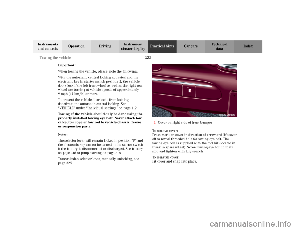
page 325.1Cover on right side of front bumper
To r e m ove c ove r :
Press mark on cover in direction of arrow and lift cover
off to reveal threaded hole for towing eye bolt. The
towing eye bolt is supplied with the tool kit (located in
trunk in spare wheel). Screw towing eye bolt in to its
stop and tighten with lug wrench.
To reinstall cover:
Fit cover and snap into place.