2001 MERCEDES-BENZ C240 torque
[x] Cancel search: torquePage 248 of 381
239 Automatic transmission
Te ch n i c a l
data Instruments
and controlsOperationDrivingInstrument
cluster displayPractical hints Car care Index Press and hold selector lever in the æ direction:
The transmission will shift from the current gear
directly to gear range “D”.
Important!
With transmission in gear range “D”, “4” or “3”,
upshifting from 1st to 2nd to 3rd gear is delayed
depending on vehicle speed and engine temperature.
This allows the catalytic converter to heat up more
quickly to operating temperatures.
During the brief warm-up period this delayed upshift
and increased engine noise might be perceived as a
malfunction. However, neither the engine nor
transmission are negatively affected by this mode of
operation.The delayed upshift is effective with vehicle speeds
below 31 mph (50 km/h) at partial throttle and engine
temperatures below 95
°F (35
°C).
To avoid overrevving the engine when the selector lever
is m ove d to a lower gear range , t he tran smi ss ion will n ot
shift to a lower gear, if the engine’s revolutions per
minute limit would be exceeded. In this case there will
be no downshift, even when the vehicle speed reaches
the engine’s rpm limit of that gear, e.g. by applying the
service brakes.
To prevent the engine from laboring at low RPM when
driving uphill gradients or with your vehicle heavily
loaded, the automatic transmission will downshift when
necessary to maintain engine RPM within the best
torque range.
Wa r n i n g !
O n s l i p p e ry ro a d s u rfa c es , n eve r d ow n s h i f t i n o rd e r
to obtain braking action. This could result in drive
wheel slip and reduced vehicle control. Your
vehicle’s ABS will not prevent this type of loss of
control.
Page 269 of 381
260 Driving systems
Te ch n i c a l
data Instruments
and controlsOperationDrivingInstrument
cluster displayPractical hints Car care Index
Electronic stability program (ESP)
The ESP enhances directional control and reduces
driving wheel spin of the vehicle under various driving
conditions.
Over/understeering of the vehicle is counteracted by
applying brakes to the appropriate wheel to create a
countervailing vehicle movement. Engine torque is also
limited. The ESP warning lamp, located in the
speedometer dial, starts to flash when ESP is in
operation.Important!
If the ESP warning lampv flashes:
•During take-off apply as little throttle as possible.
•While driving ease up on the accelerator.
•Adapt your speed and driving to the prevailing road
conditions.
•Do not switch off the ESP.
Caution!
If the vehicle is towed with the front axle raised (see
page 321, “Towing the vehicle”), the engine must be
shut off (electronic key in starter switch position 0 or 1).
Otherwise, the ESP will immediately be engaged and
will apply the rear wheel brakes.
Wa r n i n g !
ESP cannot prevent the natural laws of physics
from acting on the vehicle, nor can it increase the
traction afforded. The ESP cannot prevent
ac c id ent s, i nc l udi ng t hose resul tin g from exc es si ve
speed in turns, or aquaplaning. Only a safe,
attentive, and skillful driver can prevent accidents.
The capabilities of an ESP equipped vehicle must
never be exploited in a reckless or dangerous
manner which could jeopardize the user’s safety or
the safety of others.
Page 271 of 381
262 Driving systems
Te ch n i c a l
data Instruments
and controlsOperationDrivingInstrument
cluster displayPractical hints Car care Index
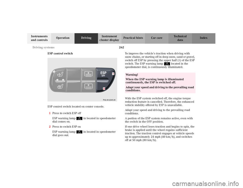
ESP control switch
ESP control switch located on center console.
1Press to switch ESP off
ESP warning lampv in located in speedometer
dial comes on.
2Press to switch ESP on
ESP warning lampv in located in speedometer
dial goes out.To improve the vehicle’s traction when driving with
sn ow chain s, or startin g of f in d eep sn ow, san d o r grave l,
switch off ESP by pressing the upper half (1) of the ESP
switch. The ESP warning lampv located in the
speedometer dial, is continuously illuminated.
With the ESP system switched off, the engine torque
reduction feature is cancelled. Therefore, the enhanced
vehicle stability offered by ESP is unavailable.
Adapt your speed and driving to the prevailing road
conditions.
A portion of the ESP system remains active, even with
the switch in the OFF position.
If one drive wheel loses traction and begins to spin, the
brake is applied until the wheel regains sufficient
traction. The traction control engages at vehicle speeds
up to approximately 24 mph (40 km / h), and switches
off at 50 mph (80 km / h).
P42.45-2245-26
Wa r n i n g !
When the ESP warning lamp is illuminated
continuously, the ESP is switched off. Ad apt your s peed an d d ri vi n g to the prevai li ng road
conditions.
Page 289 of 381
280 Malfunction and warning messages
Te ch n i c a l
data Instruments
and controlsOperation DrivingInstrument
cluster displayPractical hints Car care Index
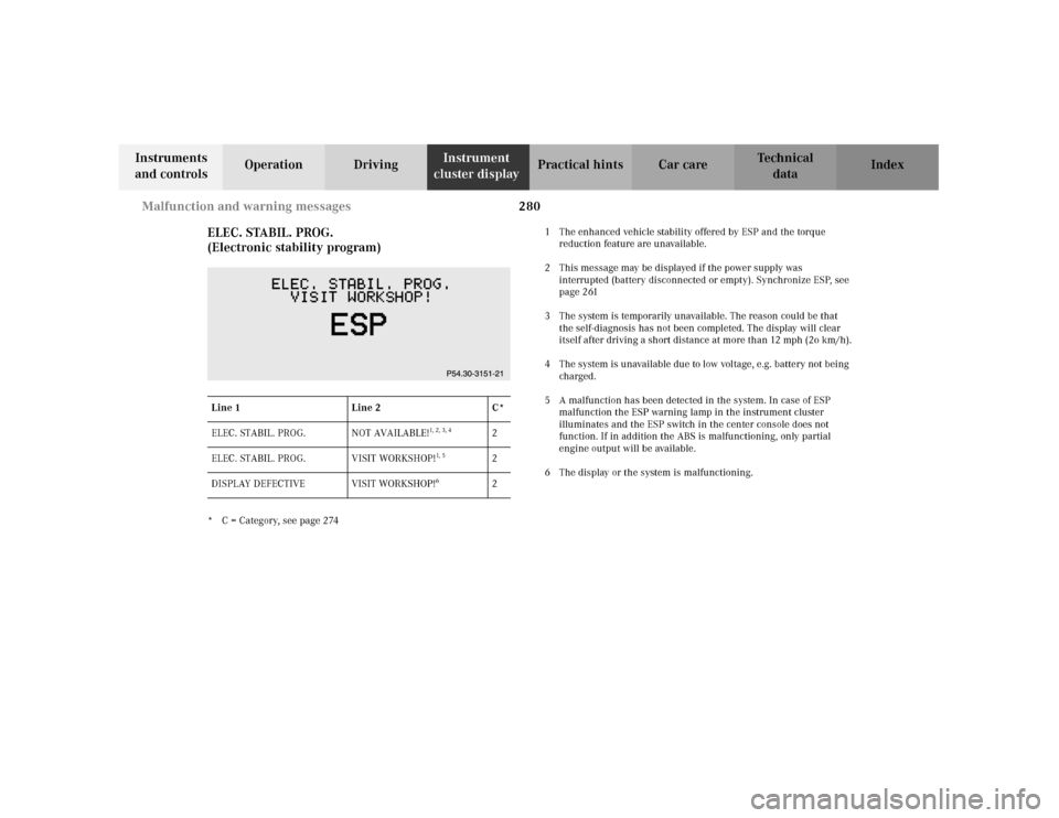
ELEC. STABIL. PROG.
(Electronic stability program)
* C = Category, see page 2741 The enhanced vehicle stability offered by ESP and the torque
reduction feature are unavailable.
2 This message may be displayed if the power supply was
interrupted (battery disconnected or empty). Synchronize ESP, see
page 261
3 The system is temporarily unavailable. The reason could be that
the self-diagnosis has not been completed. The display will clear
itself after driving a short distance at more than 12 mph (2o km/h).
4 The system is unavailable due to low voltage, e.g. battery not being
charged.
5 A malfunction has been detected in the system. In case of ESP
malfunction the ESP warning lamp in the instrument cluster
illuminates and the ESP switch in the center console does not
function. If in addition the ABS is malfunctioning, only partial
engine output will be available.
6 The display or the system is malfunctioning. Line 1 Line 2 C*
ELEC. STABIL. PROG. NOT AVAILABLE!
1, 2, 3, 4
2
ELEC. STABIL. PROG. VISIT WORKSHOP!
1, 5
2
DISPLAY DEFECTIVE VISIT WORKSHOP!
6
2
Page 316 of 381

307 Tires, Wheels
Te ch n i c a l
data Instruments
and controlsOperation DrivingInstrument
cluster displayPractical hintsCar care Index It is imperative that the wheel mounting bolts be
fastened to a tightening torque of 110 ft.lb. (150 Nm)
whenever wheels are mounted.
For rim and tire specifications, refer to “Technical Data”.Rotating wheels
The wheels can be rotated according to the degree of
tire wear while retaining the same direction of travel.
Rotating, however, should be carried out as
recommended by the tire manufacturer, before the
characteristic tire wear pattern (shoulder wear on front
wheels and tread center wear on rear wheels) becomes
visible, as otherwise the driving properties deteriorate.
Notes:
Thoroughly clean the inner side of the wheels any time
you rotate the wheels or wash the vehicle underside.
The use of retread tires is not recommended. Retread
tires may adversely affect the handling characteristics
and safety of the vehicle.
Dented or bent rims can cause tire pressure loss and
damage to the tire beads. For this reason, check rims for
damage at regular intervals. The rim flanges must be
checked for wear before a tire is mounted. Remove
burrs, if any.
Check and ensure proper tire inflation pressure after
rotating the wheels. For tire inflation pressure see
inside of fuel filler flap and also page 264.
Wa r n i n g !
Worn, old tires can cause accidents. If the tire tread
is badly worn, or if the tires have sustained
damage, replace them.When replacing rims, use only genuine
Mercedes-Benz wheel bolts specified for the
particular rim type. Failure to do so can result in
the bolts loosening and possibly an accident.
Page 323 of 381
314 Tires, Wheels
Te ch n i c a l
data Instruments
and controlsOperation DrivingInstrument
cluster displayPractical hintsCar care Index
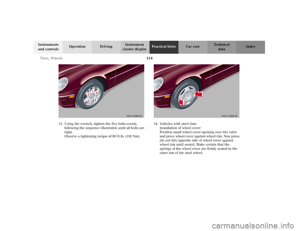
13. Using the wrench, tighten the five bolts evenly,
following the sequence illustrated, until all bolts are
tight.
Observe a tightening torque of 80 ft.lb. (110 Nm).14. Vehicles with steel rims
Installation of wheel cover:
Position small wheel cover opening over tire valve
and press wheel cover against wheel rim. Now press
(do not hit) opposite side of wheel cover against
wheel rim until seated. Make certain that the
springs of the wheel cover are firmly seated in the
outer rim of the steel wheel.
P40.10-2286-26
P40.10-2355-26
Page 360 of 381

351 Technical data
Te ch n i c a l
data Instruments
and controlsOperation DrivingInstrument
cluster displayPractical hints Car care Index Te ch n i c a l d a t a
Model C 240 (203.061
1)C 320 (203.064
1)
Engine112.912 112.946
Mode of operation 4-stroke engine, gasoline injection 4-stroke engine, gasoline injection
No. of cylinders 6 6
Bore 3.54 in (89.90 mm) 3.54 in (89.90 mm)
Stroke 2.68 in (68.20 mm) 3.30 in (84.00 mm)
Total piston displacement 158,5 cu.in. (2597 cm
3) 195.2 cu.in. (3199 cm
3)
Compression ratio 10:1 10:1
O u t p u t a c c . t o S A E J 13 4 9 16 7 h p / 6 0 0 0 r p m
(125 kW/6000 rpm)221 hp/5600 rpm
(165 kW/5600 rpm)
Maximum torque acc. to SAE J 1349 130 ft.lb/4500 rpm
(240 Nm/4500 rpm)232 ft.lb/3000 rpm
(315 Nm/3000 rpm)
Maximum engine speed 6200 rpm 6000 rpm
Firing order 1-4-3-6-2-5 1-4-3-6-2-5
Poly-V-belt 2390 mm 2390 mm
1 The quoted data apply only to the standard vehicle. See an authorized Mercedes-Benz Center for the corresponding data of all special bodies
and special equipment.
Page 362 of 381
353 Technical data
Te ch n i c a l
data Instruments
and controlsOperation DrivingInstrument
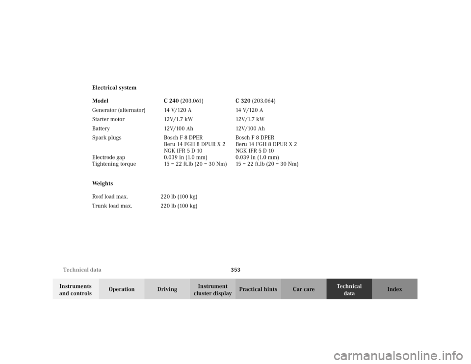
cluster displayPractical hints Car care Index Electrical system
We i g h t s Model C 240 (203.061)C 320 (203.064)
Generator (alternator) 14 V/120 A 14 V/120 A
Starter motor 12V/1.7 kW 12V/1.7 kW
B a t t e r y 12 V / 10 0 A h 12 V / 10 0 A h
Spark plugs
Electrode gap
Tightening torqueBosch F 8 DPER
Beru 14 FGH 8 DPUR X 2
NGK IFR 5 D 10
0.039 in (1.0 mm)
15–22ft.lb (20–30Nm)Bosch F 8 DPER
Beru 14 FGH 8 DPUR X 2
NGK IFR 5 D 10
0.039 in (1.0 mm)
15–22ft.lb (20–30Nm)
Roof load max. 220 lb (100 kg)
Trunk load max. 220 lb (100 kg)