Page 143 of 381
134 Combination switch
Te ch n i c a l
data Instruments
and controlsOperationDrivingInstrument
cluster displayPractical hints Car care Index
Combination switch
1Low beam
(exterior lamp switch position B)
2High beam
(exterior lamp switch position B)3High beam flasher (high beam available
independent of exterior lamp switch position)
4Turn signals, right
5Turn signals, left
To signal minor directional changes, such as changing
lanes on a highway, move combination switch briefly to
the point of resistance only and release. The turn
signals blink three times.
To operate the turn signals continuously, move the
combination switch past the point of resistance (up or
down). The switch is automatically canceled when the
steering wheel is turned to a large enough degree.
Turn signal failure
If one of the turn signals fails, the turn signal indicator
system flashes and sounds at a faster than normal rate.
Page 239 of 381
230 Starter switch
Te ch n i c a l
data Instruments
and controlsOperationDrivingInstrument
cluster displayPractical hints Car care Index
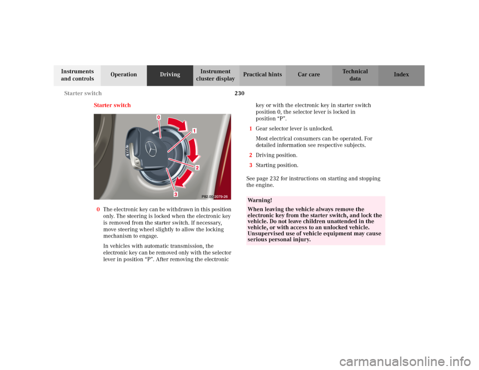
Starter switch
0The electronic key can be withdrawn in this position
only. The steering is locked when the electronic key
is removed from the starter switch. If necessary,
move steering wheel slightly to allow the locking
mechanism to engage.
In vehicles with automatic transmission, the
electronic key can be removed only with the selector
lever in position “P”. After removing the electronic key or with the electronic key in starter switch
position 0, the selector lever is locked in
position “P”.
1Gear selector lever is unlocked.
Most electrical consumers can be operated. For
detailed information see respective subjects.
2Driving position.
3Starting position.
See page 232 for instructions on starting and stopping
the engine.
Wa r n i n g !
When leaving the vehicle always remove the
electronic key from the starter switch, and lock the
vehicle. Do not leave children unattended in the
vehicle, or with access to an unlocked vehicle.
Unsupervised use of vehicle equipment may cause
serious personal injury.
Page 259 of 381
250 Driving instructions
Te ch n i c a l
data Instruments
and controlsOperationDrivingInstrument
cluster displayPractical hints Car care Index
Snow chains
Use only snow chains that are tested and recommended
by Mercedes-Benz. Your authorized Mercedes-Benz
Center will be glad to advise you on this subject.
Chains should only be used on the rear wheels. Follow
the manufacturer’s mounting instructions.
Snow chains should only be driven on snow covered
roads at speeds not to exceed 30 mph (50 km / h).
Remove chains as soon as possible when driving on
roads without snow.
When driving with snow chains, press the ESP control
switch to OFF, refer to page 262.Winter driving instructions
The most important rule for slippery or icy roads is to
drive sensibly and to avoid abrupt acceleration, braking
and steering maneuvers. Do not use the cruise control
system under such conditions.
When the vehicle is in danger of skidding, move
selector lever to position “N” or in case of manual
transmission declutch. Try to keep the vehicle under
control by corrective steering action.
Road salts and chemicals can adversely affect braking
efficiency. Increased pedal force may become necessary
to produce the normal brake effect. We therefore
recommend depressing the brake pedal periodically
when traveling at length on salt-strewn roads. This can
bring road salt impaired braking efficiency back to
normal. A prerequisite is, however, that this be done
without endangering other drivers on the road.
Page 267 of 381
258 Driving systems
Te ch n i c a l
data Instruments
and controlsOperationDrivingInstrument
cluster displayPractical hints Car care Index
Antilock brake system (ABS)
Important!
The ABS improves steering control of the vehicle during
hard braking maneuvers.
The ABS prevents the wheels from locking up above a
vehicle speed of approximately 5 mph (8 km / h)
independent of road surface conditions.At the instant one of the wheels is about to lock up, a
slight pulsation can be felt in the brake pedal,
indicating that the ABS is in the regulating mode. Keep
firm and steady pressure on the brake pedal while
experiencing the pulsation.
Continuous steady brake pedal pressure results in
applying the advantages of the ABS, namely braking
power and ability to steer the vehicle.
In the case of an emergency brake maneuver keep
continuous full pressure on the brake pedal. In this
manner only can the ABS be most effective.
On slippery road surfaces, the ABS will respond even
with light brake pedal pressure because of the
increased likelihood of locking wheels. The pulsating
brake pedal can be an indication of hazardous road
conditions and functions as a reminder to take extra
care while driving.
Wa r n i n g !
Do not pump the brake pedal, rather use firm,
steady brake pedal pressure. Pumping the brake
pedal defeats the purpose for ABS and significantly
reduces braking effectiveness.
Page 269 of 381
260 Driving systems
Te ch n i c a l
data Instruments
and controlsOperationDrivingInstrument
cluster displayPractical hints Car care Index
Electronic stability program (ESP)
The ESP enhances directional control and reduces
driving wheel spin of the vehicle under various driving
conditions.
Over/understeering of the vehicle is counteracted by
applying brakes to the appropriate wheel to create a
countervailing vehicle movement. Engine torque is also
limited. The ESP warning lamp, located in the
speedometer dial, starts to flash when ESP is in
operation.Important!
If the ESP warning lampv flashes:
•During take-off apply as little throttle as possible.
•While driving ease up on the accelerator.
•Adapt your speed and driving to the prevailing road
conditions.
•Do not switch off the ESP.
Caution!
If the vehicle is towed with the front axle raised (see
page 321, “Towing the vehicle”), the engine must be
shut off (electronic key in starter switch position 0 or 1).
Otherwise, the ESP will immediately be engaged and
will apply the rear wheel brakes.
Wa r n i n g !
ESP cannot prevent the natural laws of physics
from acting on the vehicle, nor can it increase the
traction afforded. The ESP cannot prevent
ac c id ent s, i nc l udi ng t hose resul tin g from exc es si ve
speed in turns, or aquaplaning. Only a safe,
attentive, and skillful driver can prevent accidents.
The capabilities of an ESP equipped vehicle must
never be exploited in a reckless or dangerous
manner which could jeopardize the user’s safety or
the safety of others.
Page 270 of 381
261 Driving systems
Te ch n i c a l
data Instruments
and controlsOperationDrivingInstrument
cluster displayPractical hints Car care Index Notes:
The yellow ESP warning lampv in the speedometer
dial comes on with the electronic key in starter switch
position 2. It should go out with the engine running.
If the ESP warning message is displayed, a malfunction
has been detected in the system. Pressing the
accelerator pedal will require greater effort. Only partial
engine output will be available.
Have the ESP checked at your authorized
Mercedes-Benz Center as soon as possible.
For ESP warning message, see page 273.
With the ABS malfunctioning, the ESP is also switched
off.
Driving the vehicle with varied size tires will cause the
wheels to rotate at different speeds, therefore the ESP
may activate (yellow ESP warning lamp in speedometer
d ial com es on ). For t his reas on, all wheels, in cludin g t he
spare wheel, must have the same tire size. When testing the parking brake on a brake test
dynamometer, the engine must be shut off. Otherwise,
the ESP will immediately be engaged and will apply the
rear wheel brakes.
In winter operation, the maximum effectiveness of the
ESP is only achieved with Mercedes-Benz recommended
M+S rated radial-ply tires and / or snow chains.
Synchronizing ESP
If the power supply was interrupted (battery
disconnected or empty), the ESP warning message may
be displayed with the engine running.
Turn steering wheel completely to the left and then to
the right. The ESP warning message should go out.
Page 297 of 381
288 Malfunction and warning messages
Te ch n i c a l
data Instruments
and controlsOperation DrivingInstrument
cluster displayPractical hints Car care Index
TELEPHONE – FUNCTION
* C = Category, see page 274.The display appears if button í or ì on the
multifunction steering wheel is pressed and the vehicle
is not equipped with a telephone.TELE AID
* C = Category, see page 274.
1 The Tele Aid system consists of three types of response; automatic
and manual emergency, roadside assistance and information. With
this message displayed, one or more functions may not be
avai lable.
See page 220 for notes on the Tele Aid.If a malfunction is indicated as outlined above, have the
system checked at the nearest Mercedes-Benz Center as
soon as possible.
Line 1 Line 2 C*
FUNCTION NOT AVAILABLE! 3
Line 1 Line 2 C*
TE L E A I D V I S I T WO R KS H O P !
1
1
Page 301 of 381
292 Malfunction and warning messages
Te ch n i c a l
data Instruments
and controlsOperation DrivingInstrument
cluster displayPractical hints Car care Index
STEERING WH. ADJUST
* C = Category, see page 274.For locking the manual steering wheel adjustment,
seepage77.ENTRANCE POSITION
* C = Category, see page 274.Wait until the seat and steering wheel have moved to
their driving positions. The display will clear when they
have done so.
See also page 41 for easy-entry/exit feature.
Line 1 Line 2 C*
STEERING WH. AD JU ST LOCK! 1
Line 1 Line 2 C*
ENTRANCE POSITION DO NOT DRIVE! 1