2001 LINCOLN TOWN CAR Driver door
[x] Cancel search: Driver doorPage 92 of 240
SEATING
Head restraints
Your vehicle's seats may be equipped with head restraints which are
vertically adjustable. The purpose of these head restraints is to help limit
head motion in the event of a rear collision. To properly adjust your head
restraints, lift the head restraint so that it is located directly behind your
head or as close to that position as possible. Refer to the following to
raise and lower the head restraints.
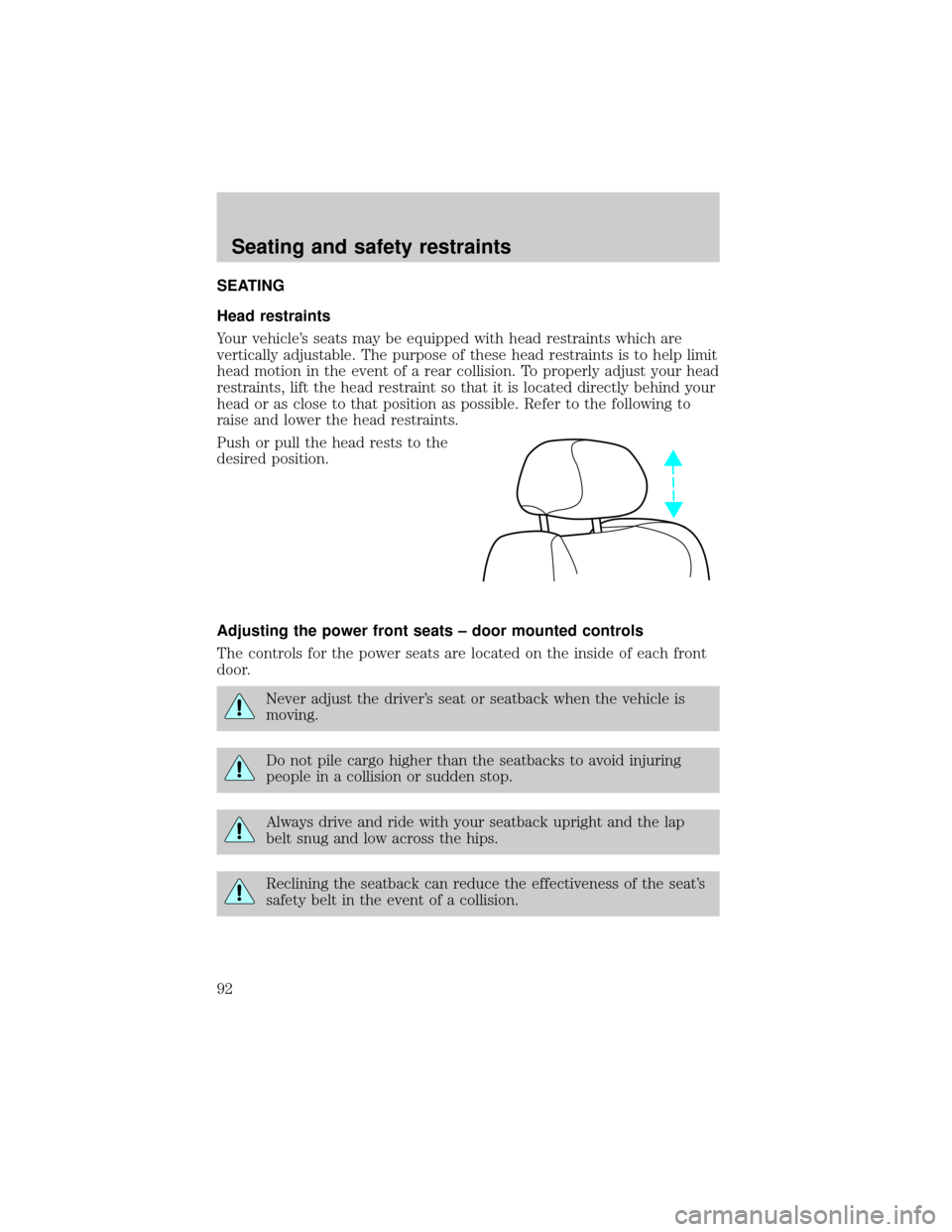
Push or pull the head rests to the
desired position.
Adjusting the power front seats ± door mounted controls
The controls for the power seats are located on the inside of each front
door.
Never adjust the driver's seat or seatback when the vehicle is
moving.
Do not pile cargo higher than the seatbacks to avoid injuring
people in a collision or sudden stop.
Always drive and ride with your seatback upright and the lap
belt snug and low across the hips.
Reclining the seatback can reduce the effectiveness of the seat's
safety belt in the event of a collision.
Seating and safety restraints
92
Page 96 of 240
Memory seats/rearview mirrors/adjustable pedals (if equipped)
This system allows automatic
positioning of the driver seat,
outside rearview mirrors, and
adjustable pedals to three
programmable positions.
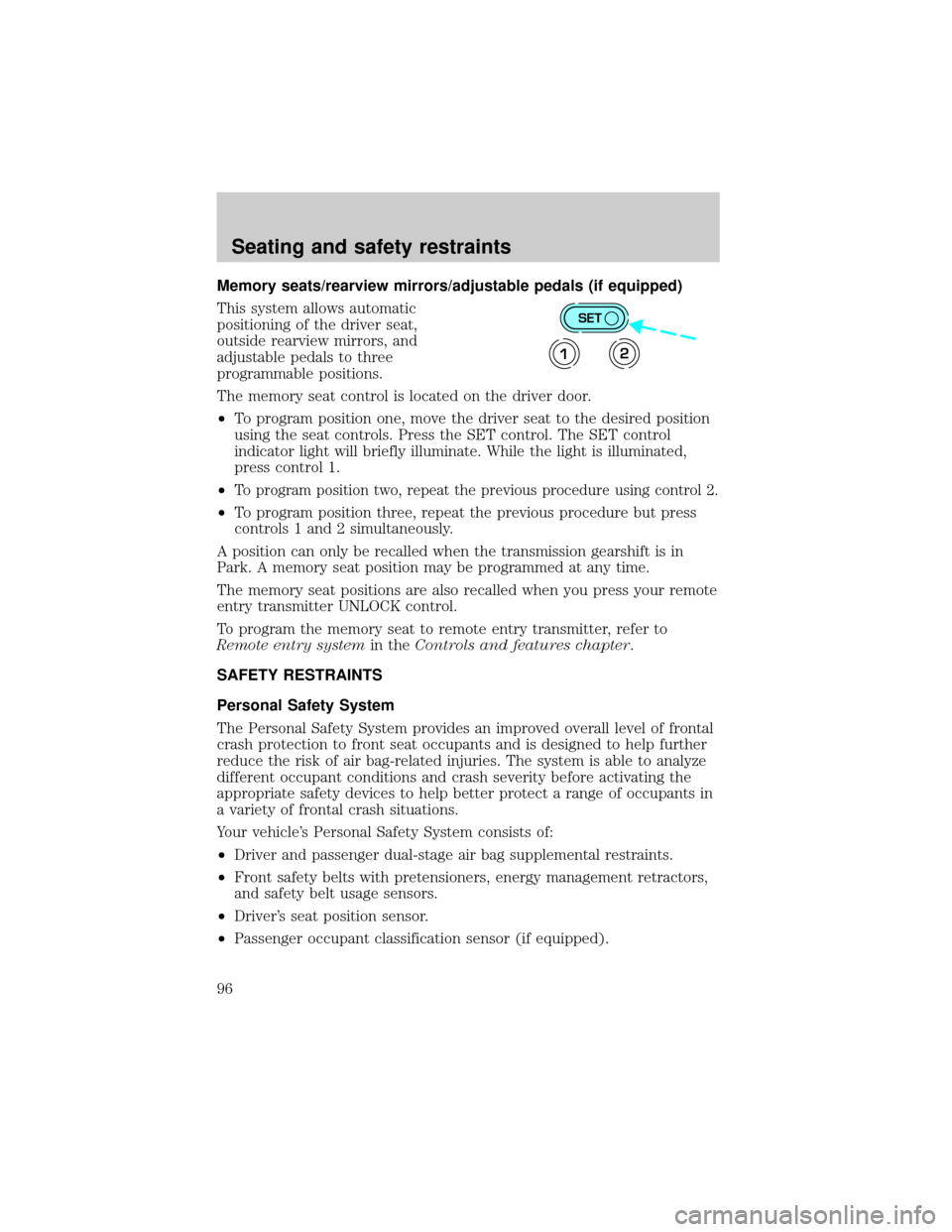
The memory seat control is located on the driver door.
²To program position one, move the driver seat to the desired position
using the seat controls. Press the SET control. The SET control
indicator light will briefly illuminate. While the light is illuminated,
press control 1.
²
To program position two, repeat the previous procedure using control 2.
²To program position three, repeat the previous procedure but press
controls 1 and 2 simultaneously.
A position can only be recalled when the transmission gearshift is in
Park. A memory seat position may be programmed at any time.
The memory seat positions are also recalled when you press your remote
entry transmitter UNLOCK control.
To program the memory seat to remote entry transmitter, refer to
Remote entry systemin theControls and features chapter.
SAFETY RESTRAINTS
Personal Safety System
The Personal Safety System provides an improved overall level of frontal
crash protection to front seat occupants and is designed to help further
reduce the risk of air bag-related injuries. The system is able to analyze
different occupant conditions and crash severity before activating the
appropriate safety devices to help better protect a range of occupants in
a variety of frontal crash situations.
Your vehicle's Personal Safety System consists of:
²Driver and passenger dual-stage air bag supplemental restraints.
²Front safety belts with pretensioners, energy management retractors,
and safety belt usage sensors.
²Driver's seat position sensor.
²Passenger occupant classification sensor (if equipped).
SET
12
Seating and safety restraints
96
Page 108 of 240
One time disable
Any time the safety belt is buckled and then unbuckled during an
ignition ON cycle, Belt Minder will be disabled for that ignition cycle
only.
Deactivating/activating the belt minder feature
Read steps1-9thoroughly before proceeding with the
deactivation/activation programming procedure.
The Belt Minder feature can be deactivated/activated by performing the
following procedure:
Before following the procedure, make sure that:
²the parking brake is set
²the gearshift is in P (Park) (automatic transmission)
²the ignition switch is in the OFF position
²all vehicle doors are closed
²the driver's safety belt is unbuckled
²the parklamps/headlamps are in OFF position (If vehicle is equipped
with Autolamps, this will not affect the procedure.)
To reduce the risk of injury, do not deactivate/activate the Belt
Minder feature while driving the vehicle.
1. Turn the ignition switch to the RUN (or ON) position. (DO NOT
START THE ENGINE)
2. Wait until the safety belt warning light turns off. (Approximately 1±2
minutes)
²Steps 3±5 must be completed within 60 seconds or the procedure will
have to be repeated.
3. Buckle then unbuckle the safety belt three times, ending with the
safety belt unbuckled. This can be done before or during Belt Minder
warning activation.
4. Turn on the parklamps/headlamps, turn off the parklamps/headlamps.
5. Buckle then unbuckle the safety belt three times, ending with the
safety belt unbuckled.
²After step 5 the safety belt warning light will be turned on for three
seconds.
Seating and safety restraints
108
Page 115 of 240
Side air bag system (if equipped)
Do not place objects or mount equipment on or near the air bag
cover on the side of the seatbacks of the front seats or in front
seat areas that may come into contact with a deploying air bag. Failure
to follow these instructions may increase the risk of personal injury in
the event of a collision.
Do not use accessory seat covers. The use of accessory seat
covers may prevent the deployment of the side air bags and
increase the risk of injury in an accident.
Do not lean your head on the door. The side air bag could injure
you as it deploys from the side of the seatback.
Do not attempt to service, repair, or modify the air bag
supplemental restraint system, its fuses or the seat cover on a
seat containing an air bag. See your Ford or Lincoln Mercury dealer.
All occupants of the vehicle including the driver should always
wear their safety belts even when an air bag SRS is provided.
Seating and safety restraints
115
Page 116 of 240
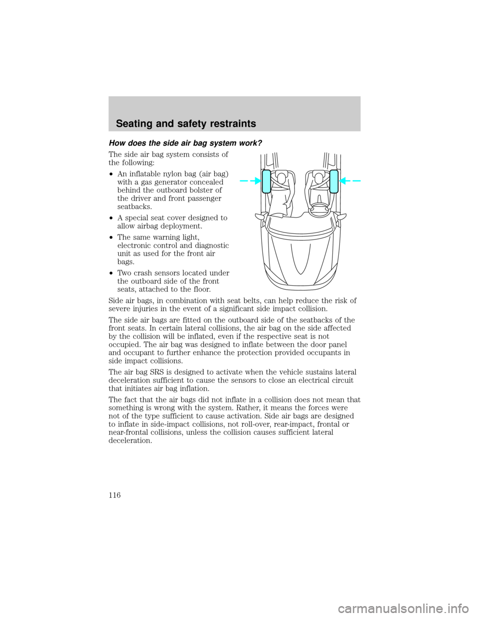
How does the side air bag system work?
The side air bag system consists of
the following:
²An inflatable nylon bag (air bag)
with a gas generator concealed
behind the outboard bolster of
the driver and front passenger
seatbacks.
²A special seat cover designed to
allow airbag deployment.
²The same warning light,
electronic control and diagnostic
unit as used for the front air
bags.
²Two crash sensors located under
the outboard side of the front
seats, attached to the floor.
Side air bags, in combination with seat belts, can help reduce the risk of
severe injuries in the event of a significant side impact collision.
The side air bags are fitted on the outboard side of the seatbacks of the
front seats. In certain lateral collisions, the air bag on the side affected
by the collision will be inflated, even if the respective seat is not
occupied. The air bag was designed to inflate between the door panel
and occupant to further enhance the protection provided occupants in
side impact collisions.
The air bag SRS is designed to activate when the vehicle sustains lateral
deceleration sufficient to cause the sensors to close an electrical circuit
that initiates air bag inflation.
The fact that the air bags did not inflate in a collision does not mean that
something is wrong with the system. Rather, it means the forces were
not of the type sufficient to cause activation. Side air bags are designed
to inflate in side-impact collisions, not roll-over, rear-impact, frontal or
near-frontal collisions, unless the collision causes sufficient lateral
deceleration.
Seating and safety restraints
116
Page 140 of 240
²GVWR (Gross Vehicle Weight Rating):Maximum permissable total
weight of the base vehicle, occupants, optional equipment and cargo.
The GVWR is specific to each vehicle and is listed on the Safety
Certification Label on the driver's door pillar.
²GAWR (Gross Axle Weight Rating):Carrying capacity for each axle
system. The GAWR is specific to each vehicle and is listed on the
Safety Certification Label on the driver's door pillar.
²GCW (Gross Combined Weight):The combined weight of the
towing vehicle (including occupants and cargo) and the loaded trailer.
²GCWR (Gross Combined Weight Rating):Maximum permissable
combined weight of the towing vehicle (including occupants and
cargo) and the loaded trailer.
²Maximum Trailer Weight Rating:Maximum weight of a trailer the
vehicle is permitted to tow. The maximum trailer weight rating is
determined by subtracting the vehicle curb weight for each
engine/transmission combination, any required option weight for trailer
towing and the weight of the driver from the GCWR for the towing
vehicle.
²Maximum Trailer Weight:Maximum weight of a trailer the loaded
vehicle (including occupants and cargo) is permitted to tow. It is
determined by subtracting the weight of the loaded trailer towing
vehicle from the GCWR for the towing vehicle.
²Trailer Weight Range:Specified weight range that the trailer must
fall within that ranges from zero to the maximum trailer weight rating.
Remember to figure in the tongue load of your loaded trailer when
figuring the total weight.
Do not exceed the GVWR or the GAWR specified on the
certification label.
Do not use replacement tires with lower load carrying capacities than the
originals because they may lower the vehicle's GVWR and GAWR
limitations. Replacement tires with a higher limit than the originals do
not increase the GVWR and GAWR limitations.
The Certification Label, found on the inside pillar of the driver's door,
lists several important vehicle weight rating limitations. Before adding
any additional equipment, refer to these limitations. If you are adding
weight to your vehicle, always ensure that the weight of occupants, cargo
Driving
140
Page 218 of 240
IDENTIFYING YOUR VEHICLE
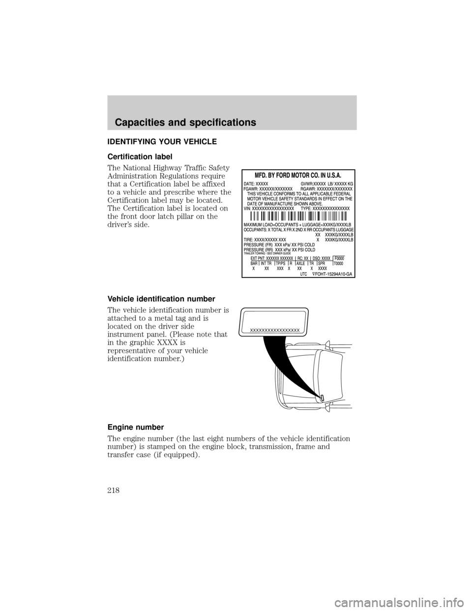
Certification label
The National Highway Traffic Safety
Administration Regulations require
that a Certification label be affixed
to a vehicle and prescribe where the
Certification label may be located.
The Certification label is located on
the front door latch pillar on the
driver's side.
Vehicle identification number
The vehicle identification number is
attached to a metal tag and is
located on the driver side
instrument panel. (Please note that
in the graphic XXXX is
representative of your vehicle
identification number.)
Engine number
The engine number (the last eight numbers of the vehicle identification
number) is stamped on the engine block, transmission, frame and
transfer case (if equipped).
XXXXXXXXXXXXXXXXX
Capacities and specifications
218
Page 240 of 240
Required fuel Unleaded fuel only - 87 octane
Fuel tank capacity 71.9L (19.0 gallons)
Engine oil capacity (includes filter
change)4.7L (5.0 quarts). Use Motorcraft
SAE 5W-20 Super Premium Motor
Oil, Ford specification
WSS-M2C153-H.
Tire pressure and size Refer to the Certification Label
located on the driver's door.
Hood release Pull handle under the left side of
the instrument panel.
Coolant capacity
115.0L (15.8 quarts)
Power steering fluid capacity Fill to line on reservoir. Use
Motorcraft MERCONtAT F.
Transmission fluid capacity
(except Signature Touring Sedan)
213.1L (13.9 quarts). Use
Motorcraft MERCONtV ATF.3
Transmission fluid capacity
(Signature Touring Sedan)212.1L (12.8 quarts). Use
Motorcraft MERCONtV ATF.3
1
Use either green-colored Motorcraft Premium Engine Coolant or
yellow-colored Motorcraft Premium Gold Engine Coolant. DO NOT USE
Ford Extended Life Engine Coolant (orange in color). Refer toAdding
engine coolant, in the Maintenance and Care chapter.
2Ensure the correct automatic transmission fluid is used. Transmission
fluid requirements are indicated on the dipstick or on the dipstick
handle. MERCONtand MERCONtV are not interchangeable. DO NOT
mix MERCONtand MERCONtV. Refer to your scheduled maintenance
guide to determine the correct service interval.
3Indicates only approximate dry-fill capacity. Some applications may vary
based on cooler size and if equipped with in-tank cooler. The amount of
transmission fluid and fluid level should be set by the indication on the
dipstick's normal operating range.
Filling station information
240