2001 LINCOLN TOWN CAR sensor
[x] Cancel search: sensorPage 113 of 240
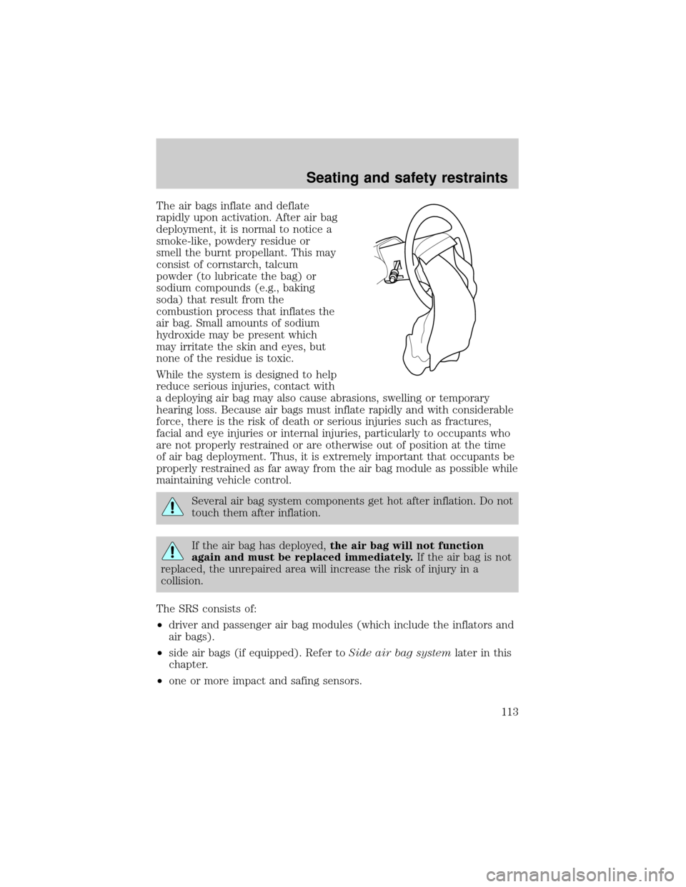
The air bags inflate and deflate
rapidly upon activation. After air bag
deployment, it is normal to notice a
smoke-like, powdery residue or
smell the burnt propellant. This may
consist of cornstarch, talcum
powder (to lubricate the bag) or
sodium compounds (e.g., baking
soda) that result from the
combustion process that inflates the
air bag. Small amounts of sodium
hydroxide may be present which
may irritate the skin and eyes, but
none of the residue is toxic.
While the system is designed to help
reduce serious injuries, contact with
a deploying air bag may also cause abrasions, swelling or temporary
hearing loss. Because air bags must inflate rapidly and with considerable
force, there is the risk of death or serious injuries such as fractures,
facial and eye injuries or internal injuries, particularly to occupants who
are not properly restrained or are otherwise out of position at the time
of air bag deployment. Thus, it is extremely important that occupants be
properly restrained as far away from the air bag module as possible while
maintaining vehicle control.
Several air bag system components get hot after inflation. Do not
touch them after inflation.
If the air bag has deployed,the air bag will not function
again and must be replaced immediately.If the air bag is not
replaced, the unrepaired area will increase the risk of injury in a
collision.
The SRS consists of:
²driver and passenger air bag modules (which include the inflators and
air bags).
²side air bags (if equipped). Refer toSide air bag systemlater in this
chapter.
²one or more impact and safing sensors.
Seating and safety restraints
113
Page 114 of 240
²a readiness light and tone.
²diagnostic module.
²and the electrical wiring which connects the components.
The diagnostic module monitors its own internal circuits and the
supplemental air bag electrical system warning (including the impact
sensors), the system wiring, the air bag system readiness light, the air
bag back up power and the air bag ignitors.
Determining if the system is operational
The SRS uses a readiness light in the instrument cluster or a tone to
indicate the condition of the system. Refer to theAir bag readiness
section in theInstrumentationchapter. Routine maintenance of the air
bag is not required.
A difficulty with the system is indicated by one or more of the following:
²The readiness light will either
flash or stay lit.
²The readiness light will not
illuminate immediately after
ignition is turned on.
²A series of five beeps will be heard. The tone pattern will repeat
periodically until the problem and/or light are repaired.
If any of these things happen, even intermittently, have the SRS serviced
at your dealership or by a qualified technician immediately. Unless
serviced, the system may not function properly in the event of a
collision.
AIR
BAG
Seating and safety restraints
114
Page 116 of 240
How does the side air bag system work?
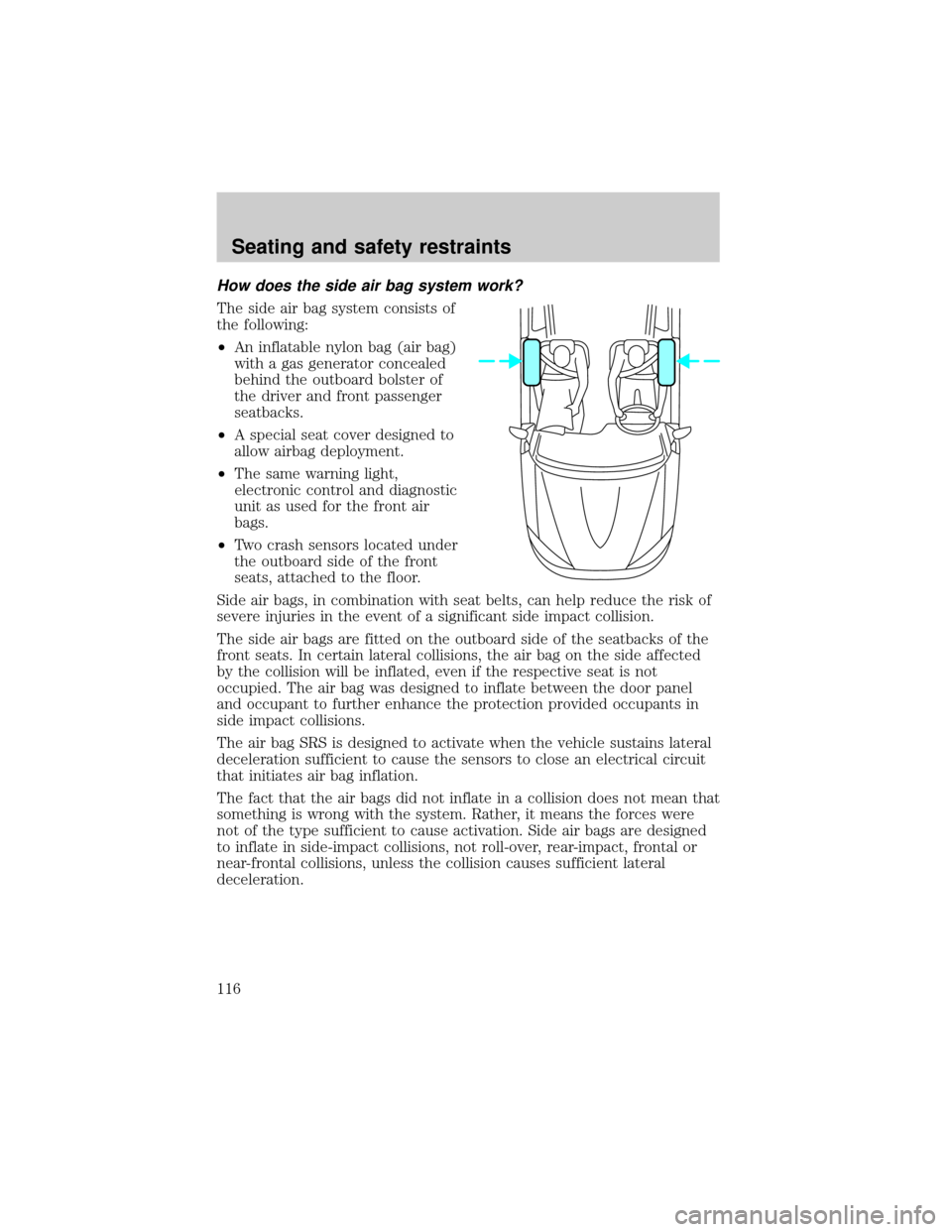
The side air bag system consists of
the following:
²An inflatable nylon bag (air bag)
with a gas generator concealed
behind the outboard bolster of
the driver and front passenger
seatbacks.
²A special seat cover designed to
allow airbag deployment.
²The same warning light,
electronic control and diagnostic
unit as used for the front air
bags.
²Two crash sensors located under
the outboard side of the front
seats, attached to the floor.
Side air bags, in combination with seat belts, can help reduce the risk of
severe injuries in the event of a significant side impact collision.
The side air bags are fitted on the outboard side of the seatbacks of the
front seats. In certain lateral collisions, the air bag on the side affected
by the collision will be inflated, even if the respective seat is not
occupied. The air bag was designed to inflate between the door panel
and occupant to further enhance the protection provided occupants in
side impact collisions.
The air bag SRS is designed to activate when the vehicle sustains lateral
deceleration sufficient to cause the sensors to close an electrical circuit
that initiates air bag inflation.
The fact that the air bags did not inflate in a collision does not mean that
something is wrong with the system. Rather, it means the forces were
not of the type sufficient to cause activation. Side air bags are designed
to inflate in side-impact collisions, not roll-over, rear-impact, frontal or
near-frontal collisions, unless the collision causes sufficient lateral
deceleration.
Seating and safety restraints
116
Page 133 of 240
TRACTION CONTROLY
For Traction Controlywarning lights refer toWarning Lightsin the
Instrumentationchapter.
Your vehicle may be equipped with the optional Traction Controly
system. This system helps you maintain the stability and steerability of
your vehicle. It is especially useful on slippery and/or hilly road surfaces.
The system operates by detecting and controlling wheel spin. The system
borrows many of the electronic and mechanical elements already present
in the anti-lock braking system (ABS).
Wheel-speed sensors allow excess rear wheel spin to be detected by the
Traction Controlyportion of the ABS computer. Any excessive wheel
spin is controlled by automatically applying and releasing the rear brakes
in conjunction with engine torque reductions. Engine torque reduction is
realized via the fully electronic spark and fuel injection systems. This
process is very sensitive to driving conditions and very fast acting. The
rear wheels ªsearchº for optimum traction several times a second and
adjustments are made accordingly.
The Traction Controlysystem will allow your vehicle to make better use
of available traction on slippery surfaces. The system is a driver aid
which makes your vehicle easier to handle primarily on snow and ice
covered roads.
During Traction Controlyoperation you may hear an electric motor type
of sound coming from the engine compartment and the engine will not
ªrev-upº when you push further on the accelerator. This is normal
system behavior.
If you should become stuck in snow
or ice or on a very slippery road
surface, try switching the Traction
Controlysystem off. This may allow
excess wheel spin to ªdigº the
vehicle out and enable a successful
ªrockingº maneuver.
Traction control switch
The traction control switch is located on the left side of the instrument
panel. The traction control system defaults to ON when the ignition key
is turned from OFF to RUN.
Driving
133
Page 149 of 240
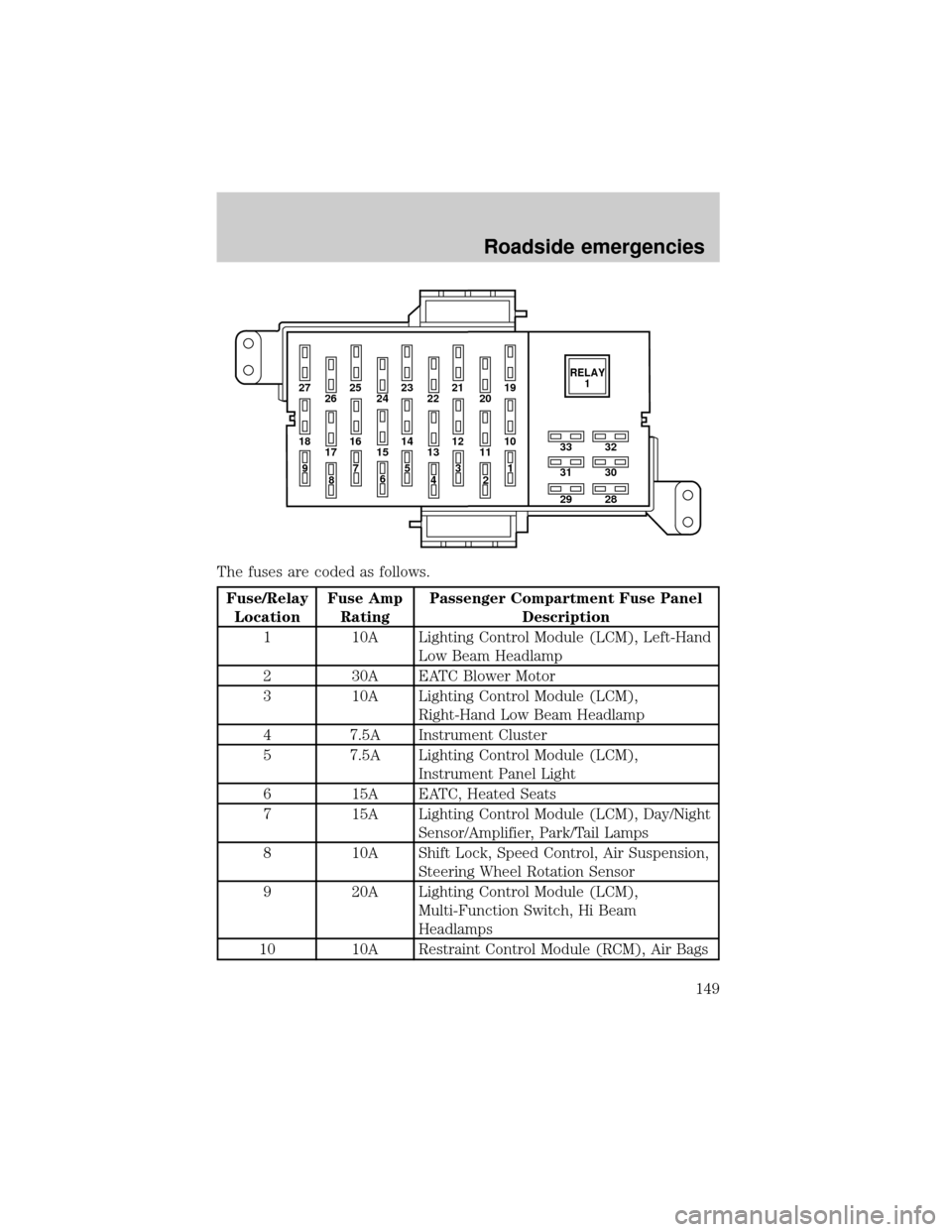
The fuses are coded as follows.
Fuse/Relay
LocationFuse Amp
RatingPassenger Compartment Fuse Panel
Description
1 10A Lighting Control Module (LCM), Left-Hand
Low Beam Headlamp
2 30A EATC Blower Motor
3 10A Lighting Control Module (LCM),
Right-Hand Low Beam Headlamp
4 7.5A Instrument Cluster
5 7.5A Lighting Control Module (LCM),
Instrument Panel Light
6 15A EATC, Heated Seats
7 15A Lighting Control Module (LCM), Day/Night
Sensor/Amplifier, Park/Tail Lamps
8 10A Shift Lock, Speed Control, Air Suspension,
Steering Wheel Rotation Sensor
9 20A Lighting Control Module (LCM),
Multi-Function Switch, Hi Beam
Headlamps
10 10A Restraint Control Module (RCM), Air Bags
27 25
26 2423 21
2219
20
18 16
17 1514 12
1310
33
31
2932
30
28 11
97
8653
41
2RELAY
1
Roadside emergencies
149
Page 150 of 240
Fuse/Relay
LocationFuse Amp
RatingPassenger Compartment Fuse Panel
Description
11 Ð Not Used
12 15A Instrument Cluster, Anti-Theft, Ignition
Switch, Ignition Coils
13 10A Anti-Lock Brake Module, Traction Control
Switch
14 7.5A Transmission Control Switch, Lighting
Control Module (LCM), VCS
15 20A Multi-Function Switch, Turn Signals
16 30A Wiper Control Module (WCM), Windshield
Wiper Motor
17 10A Digital Transmission Range (DTR) Sensor,
Back-Up Lamps, EC Mirrors
18 7.5A Lighting Control Module (LCM), Front
Radio Control Unit, Cellular Telephone
Transceiver, Electronic Day/Night Mirror,
Compass Module/Rear Audio/Climate
Control Module, VCS
19 10A EATC, Clock, Instrument Cluster, PCM
20 7.5A Lighting Control Module (LCM), ABS, Shift
Lock
21 20A Multi-Function Switch, Hazard Lamps
22 20A Multi-Function Switch, High Mounted Stop
Lamps, Stop Lamps
23 20A Datalink Connector, I/P Cigar Lighter,
Reardoor Cigar Lighters (Long Wheel Base
Only)
24 5A Front Radio Control Unit
25 15A Lighting Control Module (LCM),
Courtesy/Demand Lamps
26 5A Digital Transmission Range (DTR) Sensor,
Starter Relay Coil
27 20A Fuel Filler Door Release Switch
Roadside emergencies
150
Page 153 of 240
Fuse/Relay
LocationFuse Amp
RatingPower Distribution Box Description
11 40A** Accessory Delay Relay (Signature/Cartier),
Power Window Relay (Executive), I/P
Fuse Panel, Fuse 29,
12 30A** Air Suspension
13 30A* Rear Heated Seats (Long Wheel Base
Only)
14 20A* Rear Power Point (Long Wheel Base Only)
15 20A* Rear Power Point (Longe Wheel Base)
16 30A* Heated Seats
17 10A* Air Suspension
18 15A* Horn
19 30A* Subwoofer, I/P Fuse Panel, Fuse 33
20 15A* Fuel Injectors, PCM
21 15A* Heated Oxygen Sensors, Transmission
Solenoids, EVAP Canaster Vent Solenoid,
EGR Vacuum Regulator, EVAP Vapor
Management Valve
22 20A Fuel Pump
23 15A Charging System
24 20A* Auxiliary Power Outlet
25 30A** Passenger Seat (Long Wheel Base Only)
26 30A CB** Cooling Fan-Low Speed
27 20A** Anti-Lock Brakes
28 Ð PCM Diode
29 Ð Not used
Relay 1 Ð Fuel Pump Relay
Relay 2 Ð A/C Clutch Relay
Relay 3 Ð PCM Power Relay
Relay 4 Ð Air Suspension Relay
Relay 5 Ð Rear Defrost Relay
* Mini Fuses ** Maxi Fuses
Roadside emergencies
153
Page 235 of 240

turn signal indicator .................11
Load limits .................................139
GAWR ......................................139
GVWR ......................................139
trailer towing ..........................139
Locks
autolock .....................................83
childproof ..................................75
doors ..........................................74
Lubricant specifications ...214±215
Lumbar support, seats ...............94
M
Message center ...........................17
english/metric button ...............24
reset button ..............................18
Mirrors
automatic dimming rearview
mirror ........................................71
cleaning ...................................208
heated ........................................75
programmable memory ............84
side view mirrors (power) .......74
Moon roof ....................................71
Motorcraft parts ................194, 212
O
Octane rating ............................192
Odometer .....................................16
Oil (see Engine oil) ..................167
Overdrive .............................66, 137
P
Panic alarm feature, remote
entry system ................................81Parking brake ............................131
Parts (see Motorcraft parts) ....212
Passenger Occupant
Classification Sensor ...................98
Pedals (see Power adjustable
foot pedals) .................................58
Power distribution box (see
Fuses) ........................................151
Power door locks ........................74
Power steering ..........................134
fluid, checking and adding ....178
fluid, refill capacity ................212
fluid, specifications .........214±215
R
Radio ............................................33
Rear window defroster ...............33
Relays ........................................147
Remote entry system ...........79, 81
illuminated entry ......................83
locking/unlocking doors ...........80
opening the trunk .....................81
panic alarm ...............................81
replacement/additional
transmitters ...............................82
replacing the batteries .............81
S
Safety belts (see Safety
restraints) ..............15, 96, 100±104
Safety defects, reporting ..........230
Safety restraints ..........96, 100±104
belt minder .............................106
cleaning the safety
belts .................................109, 211
Index
235