Page 50 of 224

Cornering lamps
When the turn signal is used and the headlamps are on, the cornering
lamps will light either the right or left side depending on the direction of
the turn.
The flash rate of the turn signal will speed up considerably if the
Lighting Control Module detects a left or right turn lamp bulb (front or
rear) is burned out.
WINDSHIELD WIPER/WASHER CONTROLS
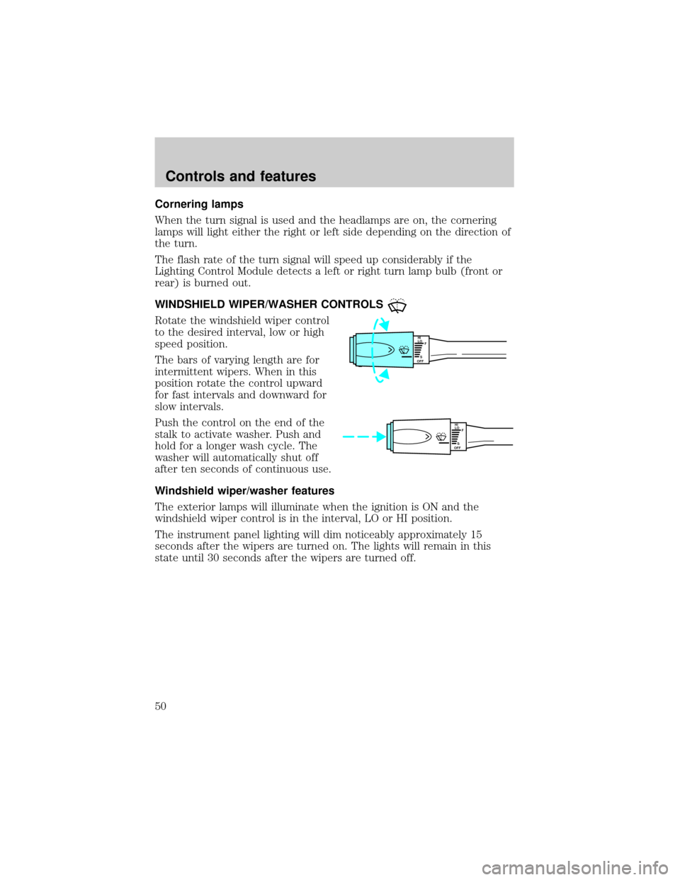
Rotate the windshield wiper control
to the desired interval, low or high
speed position.
The bars of varying length are for
intermittent wipers. When in this
position rotate the control upward
for fast intervals and downward for
slow intervals.
Push the control on the end of the
stalk to activate washer. Push and
hold for a longer wash cycle. The
washer will automatically shut off
after ten seconds of continuous use.
Windshield wiper/washer features
The exterior lamps will illuminate when the ignition is ON and the
windshield wiper control is in the interval, LO or HI position.
The instrument panel lighting will dim noticeably approximately 15
seconds after the wipers are turned on. The lights will remain in this
state until 30 seconds after the wipers are turned off.
HI
LO
F
S
OFF
HI
LO
F
S
OFF
Controls and features
50
Page 56 of 224
INTERIOR LAMPS
Map lamps
To turn on the map lamps, press the
control next to each lamp.
If equipped with a moon roof, the
map lamps are located on the
rearview mirror. Press the control
next to the map lamp to illuminate
the lamp.
Rear courtesy/reading lamps
The courtesy lamp lights when:
²any door is opened.
²the instrument panel dimmer
switch is held up until the
courtesy lamps come on.
²any of the remote entry controls
are pressed and the ignition is
OFF.
²the headlamp control is turned off.
With the ignition key in the ACC or ON position, the reading lamp can be
turned on by pressing the rocker control.
Controls and features
56
Page 70 of 224

Arming the system
When armed, this system will help protect your vehicle from
unauthorized entry. When unauthorized entry occurs, the system will
flash the headlamps, parking lamps, interior lamps and the theft indicator
lamp and will chirp the horn.
The system is ready to arm whenever the key is removed from the
ignition. Any of the following actions will prearm the alarm system:
²Lock the doors with the remote
transmitter (doors opened or
closed). The horn will chirp to
confirm that the control was
pressed. The horn chirp feature
can be turned on/off by using the
feature menu in the message
center.
²Press 7/8 and 9/0 controls on the
keyless entry pad at the same
time to lock the doors (doors
opened or closed).
²Open a door and press the power
door lock control to lock the
doors.
If a door is open, the system is prearmed and is waiting for the door to
close. The anti-theft indicator on the instrument panel will be lit
continuously when the system is prearmed.
Once the doors are closed, the system will arm in 30 seconds.
123
45678
90
Controls and features
70
Page 95 of 224

One time disable
Anytime the safety belt is buckled and then unbuckled during an ignition
ON cycle, Belt Minder will be disabled for that ignition cycle only.
Deactivating/activating the belt minder feature
Read steps1-9thoroughly before proceeding with the
deactivation/activation programming procedure.
The Belt Minder feature can be deactivated/activated by performing the
following procedure:
Before following the procedure, make sure that:
²the parking brake is set
²the gearshift is in P (Park) (automatic transmission).
²the ignition switch is in the OFF position
²all vehicle doors are closed
²the driver's safety belt is unbuckled
²the parklamps/headlamps are in OFF position (If vehicle is equipped
with Autolamps, this will not affect the procedure.)
To reduce the risk of injury, do not deactivate/activate the Belt
Minder feature while driving the vehicle.
1. Turn the ignition switch to the RUN (or ON) position. (DO NOT
START THE ENGINE)
2. Wait until the safety belt warning light turns off. (Approximately 1±2
minutes)
²Steps 3±5 must be completed within 60 seconds or the procedure will
have to be repeated.
3. Buckle then unbuckle the safety belt three times, ending with the
safety belt unbuckled. This can be done before or during Belt Minder
warning activation.
4. Turn on the parklamps/headlamps, turn off the parklamps/headlamps.
5. Buckle then unbuckle the safety belt three times, ending with the
safety belt unbuckled.
²After step 5 the safety belt warning light will be turned on for three
seconds.
Seating and safety restraints
95
Page 113 of 224
2. Make sure the headlamps and vehicle accessories are off.
²Make sure the parking brake is
set.
²Make sure the gearshift is in P
(Park).
3. Turn the key to 4 (ON) without
turning the key to 5 (START).
If there is difficulty in turning the
key, firmly rotate the steering wheel
left and right until the key turns
freely. This condition may occur
when:
²front wheels are turned
²front wheel is against the curb
²steering wheel is turned when getting in or out of the vehicle
BRAKE RELEASEHOOD
1
2
34
5
Starting
113
Page 137 of 224

Fuse/Relay
LocationFuse Amp
RatingPassenger Compartment
Fuse Panel Description
5 10A Virtual Image Instrument Cluster, Lighting
Control Module (LCM RUN/START Sense),
Autolamp Light Sensor
6 10A Virtual Image Instrument Cluster, RF
Park/Turn Lamp
7 20A Power Point
8 20A Fuel Filler Door Release Switch, Trunk Lid
Relay
9 10A Air Bag Diagnostic Monitor, EATC Module,
Blower Motor Relay
10 30A Windshield Wiper Motor, Windshield Wiper
Module
11 10A Ignition Coils, Radio Interference Capacitor,
PCM Power Relay, Passive Anti-Theft
System (PATS) Transceiver
12 10A Lighting Control Module
13 15A Lighting Control Module (LCM): RF Turn
Lamp, Right Turn Indicator (VIC), RR Side
Marker Lamps, Tail Lamps, License Lamps,
LR Stop/Turn Lamps, Clock Illumination
14 20A Cigar Lighter
15 10A ABS Evac and Fill Connector
16 30A Moonroof Switch
17 Ð Not Used
18 10A Lighting Control Module
19 10A Lighting Control Module (LCM): Left
Headlamp, DRL
20 15A Multi-Function Switch: Flash to Pass, and
Hazard Warning Input to LCM
21 Ð Not Used
22 Ð Not Used
23 10A Digital Transmission Range Sensor
24 10A Virtual Image Cluster-LF Turn Indicator, LF
Turn Signal
Roadside emergencies
137
Page 138 of 224

Fuse/Relay
LocationFuse Amp
RatingPassenger Compartment
Fuse Panel Description
25 10A Lighting Control Module (LCM): Right
Headlamp
26 10A Virtual Image Instrument Cluster, EATC
Module
27 Ð Not Used
28 10A Shift Lock Actuator, Vehicle Dynamic
Module, Virtual Image Instrument Cluster,
Rear Window Defrost, Heated Seat Switch
Assembly, Low Tire Pressure Module
29 10A Radio
30 10A Heated Mirrors
31 15A Lighting Control Module (LCM): FCU,
Electronic Day/Night Mirror, RH and LH
Courtesy Lamp, Door Courtesy Lamps, RH
and LH Map Lamps, RR and LR Reading
Lamps, RH and LH Visor Lamps, Storage
Bin Lamps, Trunk Lid Lamp, Glove Box
Lamp, Light Sensor Amplifier
32 15A Speed Control DEAC. Switch, Brake On/Off
(BOO) Switch
33 Ð Not Used
34 15A Console Shift Illumination, A/C Clutch
Cycling Pressure Switch, A/C Clutch Relay
(DTR) Sensor, Intake Manifold Runner
Control, Backup Lamps
35 Ð Not Used
36 Ð Not Used
37 30A Subwoofer Amplifier, Radio
38 10A Analog Clock, CD Player, Mobile Telephone
Transceiver, RESCU
39 10A Power Door Locks, Power Seats, Power
Mirrors, Keyless Entry, LF Seat Module, LF
Door Module
40 10A Cornering Lamps
41 20A Door Locks
Roadside emergencies
138
Page 186 of 224

engine must warm up to its normal operating temperature. Once started,
do not turn off the engine until the above driving cycle is complete.
REPLACING EXTERIOR BULBS
Check the operation of the following lamps frequently:
²Headlamps
²Tail lamps
²Brakelamps
²High-mount brakelamp
²Turn signals
²Backup lamps
²License plate lamp
Do not remove lamp bulbs unless they will be replaced immediately. If a
bulb is removed for an extended period of time, contaminants may enter
the lamp housings and affect performance.
Replacing headlamp bulbs
To remove the headlamp bulb:
1. Make sure headlamp switch is in OFF position.
2. Lift the hood and remove the protective cover from the top of the
headlamps by lifting up on the rear corners and release the velcro
attachments. Lift the cover and pull towards the windshield.
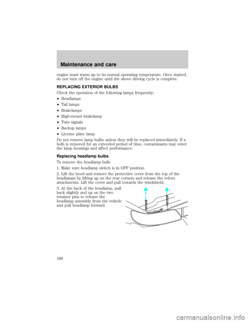
3. At the back of the headlamp, pull
back slightly and up on the two
retainer pins to release the
headlamp assembly from the vehicle
and pull headlamp forward.
Maintenance and care
186