Page 1843 of 2395
Self-diagnosis=NBHA0021INTRODUCTION AND GENERAL DESCRIPTIONNBHA0021S01The self-diagnostic system diagnoses sensors, door motors, blower motor, etc. by system line. Refer to appli-
cable sections (items) for details. Shifting from normal control to the self-diagnostic system is accomplished
by starting the engine (turning the ignition switch from ªOFFº to ªONº) and pressing ª
º switch for at least
5 seconds. The ª
º switch must be pressed within 10 seconds after starting the engine (ignition switch is
turned ªONº). This system will be canceled by either pressing
(AUTO) switch or turning the ignition switch
ªOFFº. Shifting from one step to another is accomplished by means of pushing
(HOT) or(COLD) switch,
as required.
Additionally shifting from STEP 5 to AUXILIARY MECHANISM is accomplished by means of pushing
(fan)
UP switch.
Without Navigation SystemNBHA0021S0101
RHA453GA
TROUBLE DIAGNOSES
Self-diagnosis
HA-44
Page 1844 of 2395
STEP-BY-STEP PROCEDURE=NBHA0021S02Without Navigation SystemNBHA0021S0201
1 SET IN SELF-DIAGNOSTIC MODE
1. Turn ignition switch ON.
2. Set in self-diagnostic mode as follows. Within 10 seconds after starting engine (ignition switch is turned ªONº.), press
switch for at least 5 seconds.
©GO TO 2.
2 STEP 1 - ALL LEDs AND SEGMENT ARE CHECKED
Do all LEDs and segments illuminate?
RHA454G
YesorNo
Ye s©GO TO 3.
No©Malfunctioning
switch, LED or fluorescent display tube.
Replace A/C auto amp.
3 VERIFY ADVANCE TO SELF-DIAGNOSIS STEP 2
1. Press(HOT) switch.
2. Does advance to self-diagnosis STEP 2?
YesorNo
Ye s©GO TO 4.
No©Malfunctioning
(HOT) switch.
Replace A/C auto amp.
4 VERIFY RETURN TO SELF-DIAGNOSIS STEP 1
1. Press(COLD) switch.
2. Does return to self-diagnosis STEP 1?
YesorNo
Ye s©GO TO 5.
No©Malfunctioning
(COLD) switch.
Replace A/C auto amp.
GI
MA
EM
LC
EC
FE
AT
TF
PD
AX
SU
BR
ST
RS
BT
SC
EL
IDX
TROUBLE DIAGNOSES
Self-diagnosis (Cont'd)
HA-45
Page 1852 of 2395
AUXILIARY MECHANISM: TEMPERATURE SETTING TRIMMER=NBHA0021S03Without Navigation SystemNBHA0021S0301The trimmer compensates for differences in range of±3ÉC (±6ÉF) between temperature setting (displayed
digitally) and temperature felt by driver.
Operating procedures for this trimmer are as follows:
IBegin Self-diagnosis STEP 5 mode.
IPress
(fan) UP switch to set system in auxiliary mode.
IDisplay shows ª
º in auxiliary mechanism.
It takes approximately 3 seconds.
IPress either
(HOT) or(COLD) switch as desired. Temperature will change at a rate of 0.5ÉC (1ÉF)
each time a switch is pressed.
SHA197E
When battery cable is disconnected, trimmer operation is canceled. Temperature set becomes that of
initial condition, i.e. 0ÉC (0ÉF).
GI
MA
EM
LC
EC
FE
AT
TF
PD
AX
SU
BR
ST
RS
BT
SC
EL
IDX
TROUBLE DIAGNOSES
Self-diagnosis (Cont'd)
HA-53
Page 1853 of 2395
INTRODUCTION AND GENERAL DESCRIPTIONNBHA0021S04The self-diagnostic system diagnoses sensors, door motors, blower motor, etc. by system line. Refer to appli-
cable sections (items) for details. Shifting from normal control to the self-diagnostic system is accomplished
by starting the engine (turning the ignition switch from ªOFFº to ªONº) and pressing ª
º switch for at least
5 seconds. The ª
º switch must be pressed within 10 seconds after starting the engine (ignition switch is
turned ªONº). This system will be canceled by either pressing
(AUTO) switch or turning the ignition switch
ªOFFº. Shifting from one step to another is accomplished by means of turning temperature dial, as required.
Additionally shifting from STEP 5 to AUXILIARY MECHANISM is accomplished by means of pushing
(fan)
UP switch.
With Navigation SystemNBHA0021S0401
RHA859H
TROUBLE DIAGNOSES
Self-diagnosis (Cont'd)
HA-54
Page 1854 of 2395

STEP-BY-STEP PROCEDURENBHA0021S05With Navigation SystemNBHA0021S0501
1 SET IN SELF-DIAGNOSTIC MODE
1. Turn ignition switch ON.
2. Set in self-diagnostic mode as follows. Within 10 seconds after starting engine (ignition switch is turned ªONº.), press
switch for at least 5 seconds.
©GO TO 2.
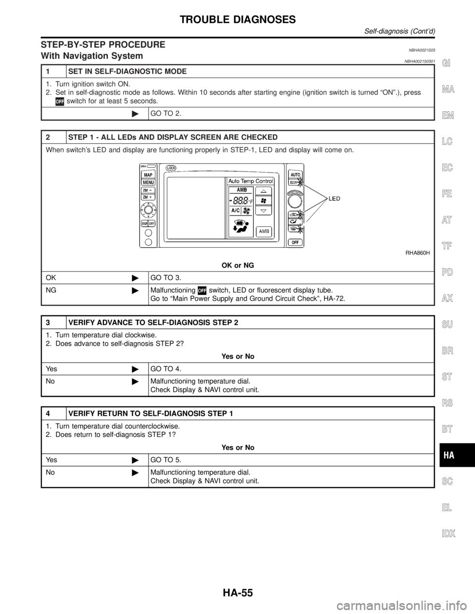
2 STEP 1 - ALL LEDs AND DISPLAY SCREEN ARE CHECKED
When switch's LED and display are functioning properly in STEP-1, LED and display will come on.
RHA860H
OK or NG
OK©GO TO 3.
NG©Malfunctioning
switch, LED or fluorescent display tube.
Go to ªMain Power Supply and Ground Circuit Checkº, HA-72.
3 VERIFY ADVANCE TO SELF-DIAGNOSIS STEP 2
1. Turn temperature dial clockwise.
2. Does advance to self-diagnosis STEP 2?
YesorNo
Ye s©GO TO 4.
No©Malfunctioning temperature dial.
Check Display & NAVI control unit.
4 VERIFY RETURN TO SELF-DIAGNOSIS STEP 1
1. Turn temperature dial counterclockwise.
2. Does return to self-diagnosis STEP 1?
YesorNo
Ye s©GO TO 5.
No©Malfunctioning temperature dial.
Check Display & NAVI control unit.
GI
MA
EM
LC
EC
FE
AT
TF
PD
AX
SU
BR
ST
RS
BT
SC
EL
IDX
TROUBLE DIAGNOSES
Self-diagnosis (Cont'd)
HA-55
Page 1860 of 2395
13 DETECTS MULTIPLEX COMMUNICATION ERROR
Press REC switch.
Does code No.
appears on the display
MTBL0509
YesorNo
Ye s©INSPECTION END
No©1. Go to ªMultiplex Communication Circuitº, HA-142.
2. Go to ªOPERATIONAL CHECKº, HA-66.
Confirm that A/C system is in good order.
GI
MA
EM
LC
EC
FE
AT
TF
PD
AX
SU
BR
ST
RS
BT
SC
EL
IDX
TROUBLE DIAGNOSES
Self-diagnosis (Cont'd)
HA-61
Page 1863 of 2395
AUXILIARY MECHANISM: TEMPERATURE SETTING TRIMMER=NBHA0021S06With Navigation SystemNBHA0021S0601The trimmer compensates for differences in range of±3ÉC (±6ÉF) between temperature setting (displayed
digitally) and temperature felt by driver.
Operating procedures for this trimmer are as follows:
IBegin Self-diagnosis STEP 5 mode.
IPress
(fan) UP switch to set system in auxiliary mode.
IDisplay shows ª
º in auxiliary mechanism.
It takes approximately 3 seconds.
ITurn the temperature dial clockwise or counterclockwise: Temperature will change at a rate of 0.5ÉC (1ÉF).
RHA863H
When battery cable is disconnected, trimmer operation is canceled. Temperature set becomes that of
initial condition, i.e. 0ÉC (0ÉF).
TROUBLE DIAGNOSES
Self-diagnosis (Cont'd)
HA-64
Page 1864 of 2395

How to Perform Trouble Diagnoses for Quick
and Accurate Repair
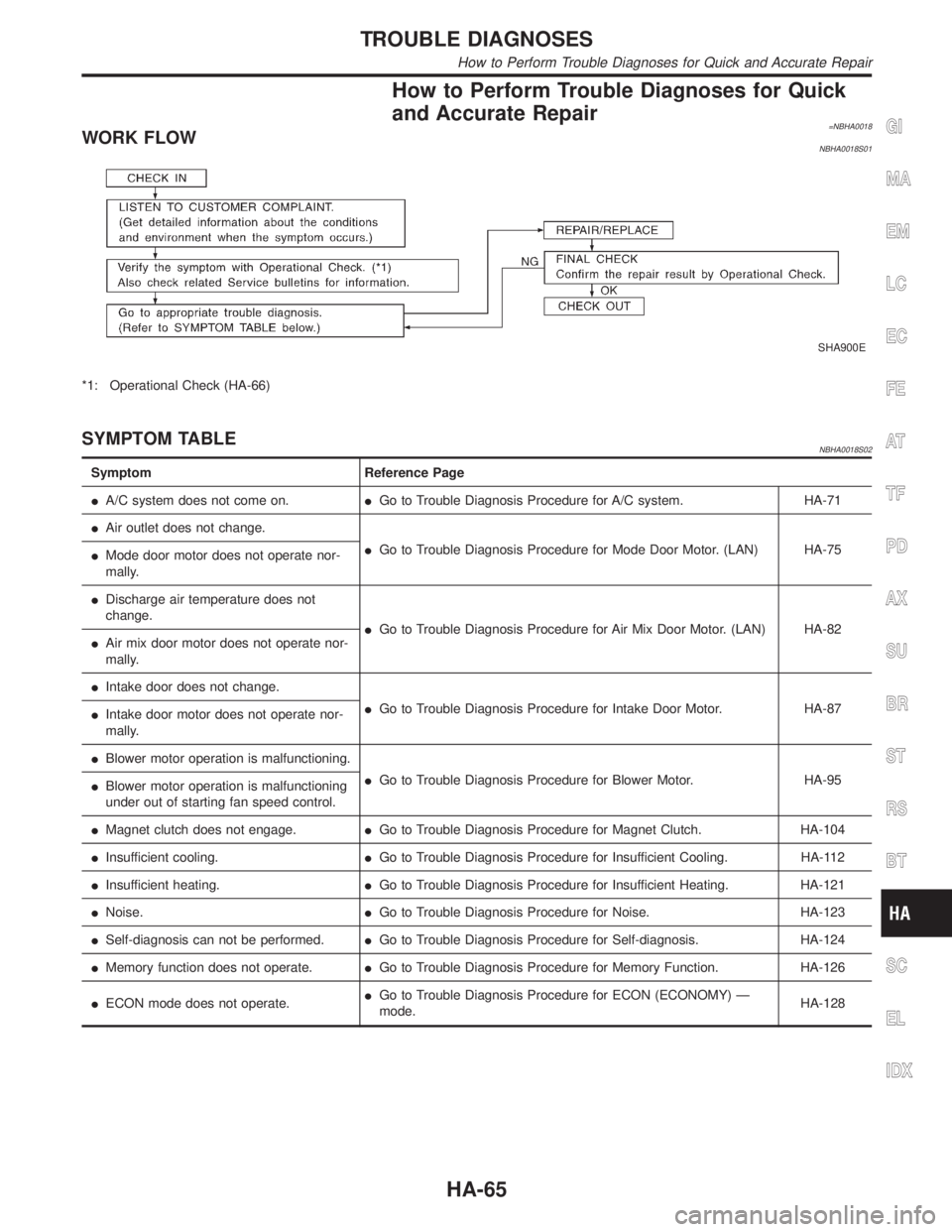
=NBHA0018WORK FLOWNBHA0018S01
SHA900E
*1: Operational Check (HA-66)
SYMPTOM TABLENBHA0018S02
Symptom Reference Page
IA/C system does not come on.IGo to Trouble Diagnosis Procedure for A/C system. HA-71
IAir outlet does not change.
IGo to Trouble Diagnosis Procedure for Mode Door Motor. (LAN) HA-75
IMode door motor does not operate nor-
mally.
IDischarge air temperature does not
change.
IGo to Trouble Diagnosis Procedure for Air Mix Door Motor. (LAN) HA-82
IAir mix door motor does not operate nor-
mally.
IIntake door does not change.
IGo to Trouble Diagnosis Procedure for Intake Door Motor. HA-87
IIntake door motor does not operate nor-
mally.
IBlower motor operation is malfunctioning.
IGo to Trouble Diagnosis Procedure for Blower Motor. HA-95
IBlower motor operation is malfunctioning
under out of starting fan speed control.
IMagnet clutch does not engage.IGo to Trouble Diagnosis Procedure for Magnet Clutch. HA-104
IInsufficient cooling.IGo to Trouble Diagnosis Procedure for Insufficient Cooling. HA-112
IInsufficient heating.IGo to Trouble Diagnosis Procedure for Insufficient Heating. HA-121
INoise.IGo to Trouble Diagnosis Procedure for Noise. HA-123
ISelf-diagnosis can not be performed.IGo to Trouble Diagnosis Procedure for Self-diagnosis. HA-124
IMemory function does not operate.IGo to Trouble Diagnosis Procedure for Memory Function. HA-126
IECON mode does not operate.IGo to Trouble Diagnosis Procedure for ECON (ECONOMY) Ð
mode.HA-128
GI
MA
EM
LC
EC
FE
AT
TF
PD
AX
SU
BR
ST
RS
BT
SC
EL
IDX
TROUBLE DIAGNOSES
How to Perform Trouble Diagnoses for Quick and Accurate Repair
HA-65