2001 INFINITI QX4 remote control
[x] Cancel search: remote controlPage 1783 of 2395

NBGI0006
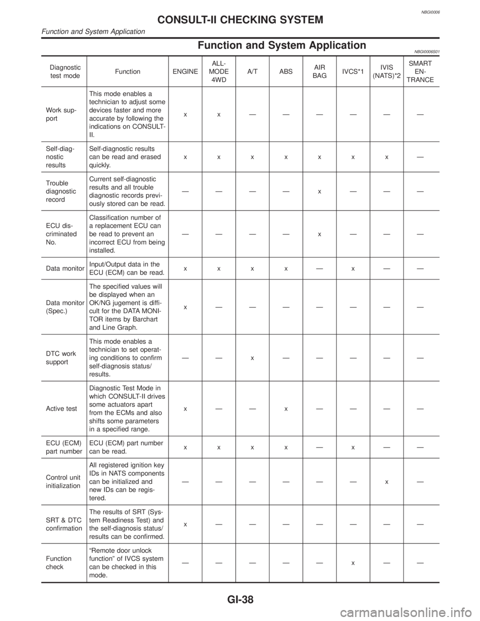
Function and System ApplicationNBGI0006S01
Diagnostic
test modeFunction ENGINEALL-
MODE
4WDA/T ABSAIR
BAGIVCS*1IVIS
(NATS)*2SMART
EN-
TRANCE
Work sup-
portThis mode enables a
technician to adjust some
devices faster and more
accurate by following the
indications on CONSULT-
II.x x ÐÐÐÐÐÐ
Self-diag-
nostic
resultsSelf-diagnostic results
can be read and erased
quickly.xxxxxxxÐ
Trouble
diagnostic
recordCurrent self-diagnostic
results and all trouble
diagnostic records previ-
ously stored can be read.ÐÐÐÐ x ÐÐÐ
ECU dis-
criminated
No.Classification number of
a replacement ECU can
be read to prevent an
incorrect ECU from being
installed.ÐÐÐÐ x ÐÐÐ
Data monitorInput/Output data in the
ECU (ECM) can be read.x x x xÐxÐÐ
Data monitor
(Spec.)The specified values will
be displayed when an
OK/NG jugement is diffi-
cult for the DATA MONI-
TOR items by Barchart
and Line Graph.x ÐÐÐÐÐÐÐ
DTC work
supportThis mode enables a
technician to set operat-
ing conditions to confirm
self-diagnosis status/
results.ÐÐ x ÐÐÐÐÐ
Active testDiagnostic Test Mode in
which CONSULT-II drives
some actuators apart
from the ECMs and also
shifts some parameters
in a specified range.x ÐÐ x ÐÐÐÐ
ECU (ECM)
part numberECU (ECM) part number
can be read.x x x xÐxÐÐ
Control unit
initializationAll registered ignition key
IDs in NATS components
can be initialized and
new IDs can be regis-
tered.ÐÐÐÐÐÐ x Ð
SRT & DTC
confirmationThe results of SRT (Sys-
tem Readiness Test) and
the self-diagnosis status/
results can be confirmed.x ÐÐÐÐÐÐÐ
Function
checkªRemote door unlock
functionº of IVCS system
can be checked in this
mode.ÐÐÐÐÐ x ÐÐ
CONSULT-II CHECKING SYSTEM
Function and System Application
GI-38
Page 1784 of 2395

Diagnostic
test modeFunction ENGINEALL-
MODE
4WDA/T ABSAIR
BAGIVCS*1IVIS
(NATS)*2SMART
EN-
TRANCE
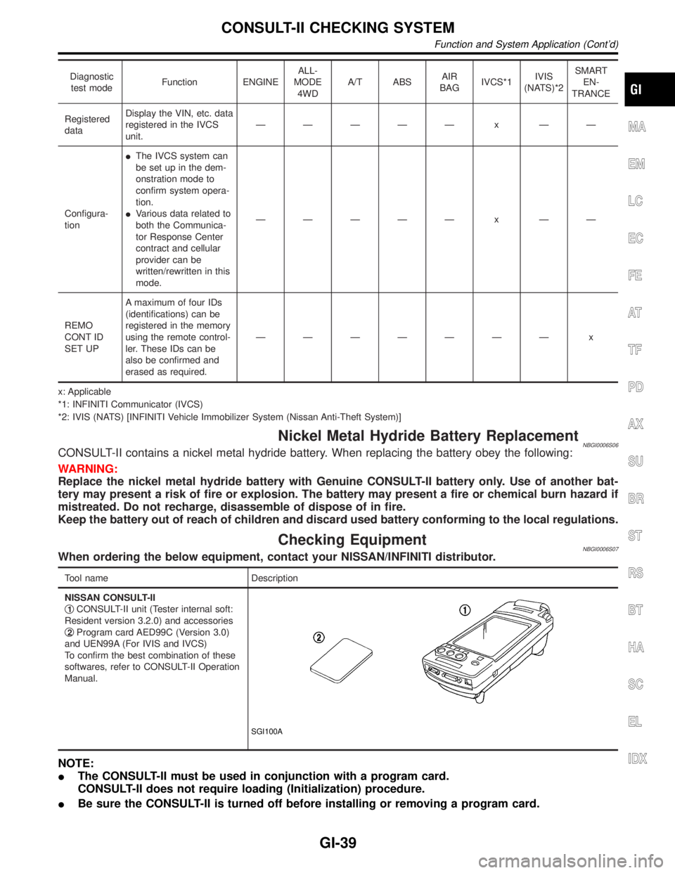
Registered
dataDisplay the VIN, etc. data
registered in the IVCS
unit.ÐÐÐÐÐ x ÐÐ
Configura-
tionIThe IVCS system can
be set up in the dem-
onstration mode to
confirm system opera-
tion.
IVarious data related to
both the Communica-
tor Response Center
contract and cellular
provider can be
written/rewritten in this
mode.ÐÐÐÐÐ x ÐÐ
REMO
CONT ID
SET UPA maximum of four IDs
(identifications) can be
registered in the memory
using the remote control-
ler. These IDs can be
also be confirmed and
erased as required.ÐÐÐÐÐÐÐ x
x: Applicable
*1: INFINITI Communicator (IVCS)
*2: IVIS (NATS) [INFINITI Vehicle Immobilizer System (Nissan Anti-Theft System)]
Nickel Metal Hydride Battery ReplacementNBGI0006S06CONSULT-II contains a nickel metal hydride battery. When replacing the battery obey the following:
WARNING:
Replace the nickel metal hydride battery with Genuine CONSULT-II battery only. Use of another bat-
tery may present a risk of fire or explosion. The battery may present a fire or chemical burn hazard if
mistreated. Do not recharge, disassemble of dispose of in fire.
Keep the battery out of reach of children and discard used battery conforming to the local regulations.
Checking EquipmentNBGI0006S07When ordering the below equipment, contact your NISSAN/INFINITI distributor.
Tool name Description
NISSAN CONSULT-II
q
1CONSULT-II unit (Tester internal soft:
Resident version 3.2.0) and accessories
q
2Program card AED99C (Version 3.0)
and UEN99A (For IVIS and IVCS)
To confirm the best combination of these
softwares, refer to CONSULT-II Operation
Manual.
SGI100A
NOTE:
IThe CONSULT-II must be used in conjunction with a program card.
CONSULT-II does not require loading (Initialization) procedure.
IBe sure the CONSULT-II is turned off before installing or removing a program card.
MA
EM
LC
EC
FE
AT
TF
PD
AX
SU
BR
ST
RS
BT
HA
SC
EL
IDX
CONSULT-II CHECKING SYSTEM
Function and System Application (Cont'd)
GI-39
Page 1965 of 2395

LSV (Load sensing valve) ..............................BR-12
Lubricant (R134a) A/C..................................HA-146
Lubricants .......................................................MA-11
Lubrication circuit (engine) ...............................LC-3
Lubrication-locks, hinges and hood
latches ........................................................MA-27
Luggage room lamp ........................................EL-88
M
MAFS - Wiring diagram................................EC-154
Magnet clutch .......................................HA-104, 150
MAIN - Wiring diagram.................................EC-142
Main oil pump (Transfer)...............................TF-131
Mainshaft (Transfer) ......................................TF-125
Maintenance (engine) ....................................MA-13
MAJOR OVERHALL......................................AT-281
Major overhaul (Transfer) .............................TF-120
Malfunction indicator lamp (MIL) ....................EC-74
Mass air flow sensor (MAFS) .......................EC-150
Master cylinder (brake) ..................................BR-16
Meter ...............................................................EL-94
METER - Wiring diagram................................EL-99
MIL & Data link connectors circuit ...............EC-648
MIL/DL - Wiring diagram ..............................EC-648
MIRROR - Wiring diagram............................EL-177
Mirror defogger .............................................EL-151
Mirror, door......................................................BT-56
Mirror, out side ................................................BT-56
Misfire ...........................................................EC-320
Mode door control linkage adjustment ...........HA-81
Mode door motor ............................................HA-75
Model variation ................................................GI-41
Molding - See Exterior ....................................BT-35
MULTI - Wiring diagram ................................EL-274
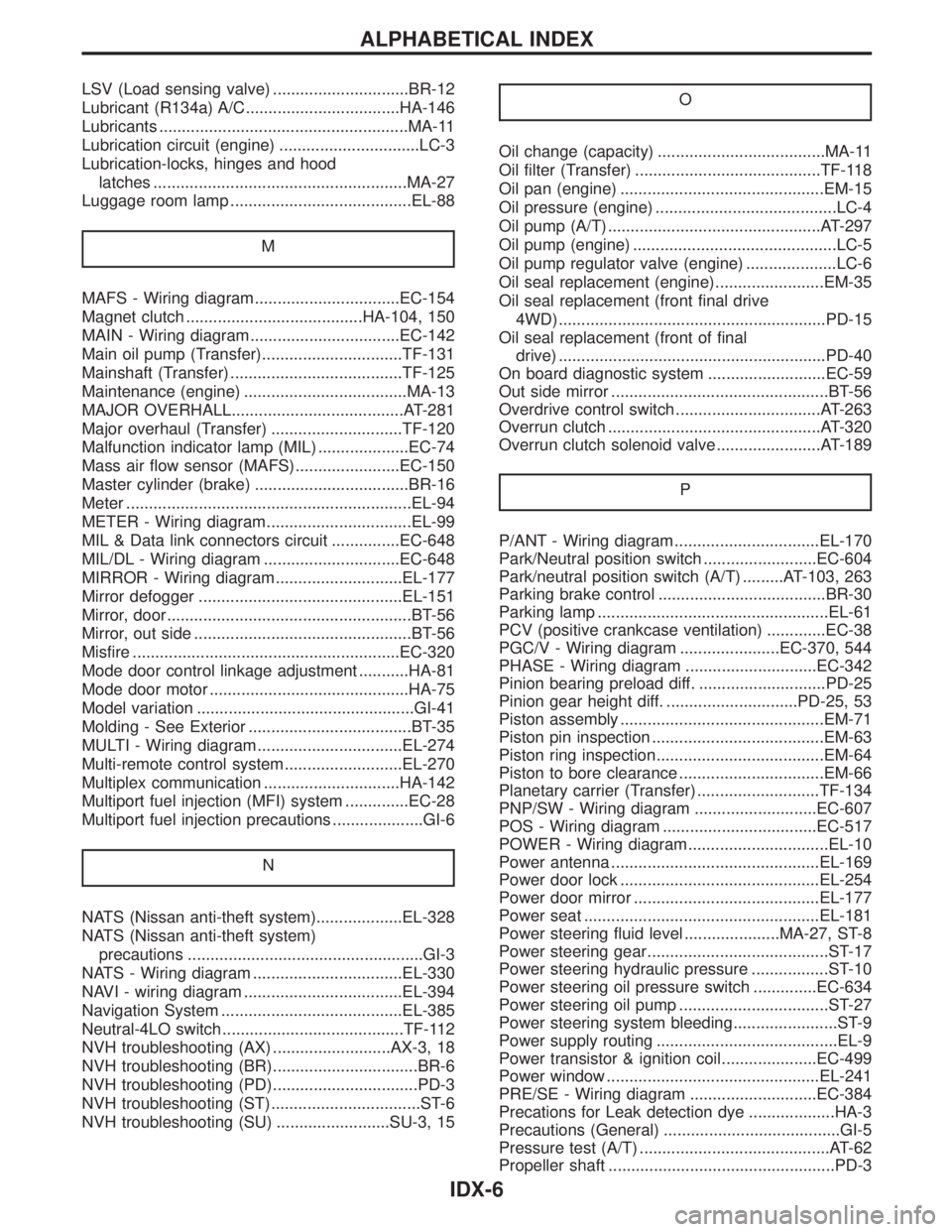
Multi-remote control system..........................EL-270
Multiplex communication ..............................HA-142
Multiport fuel injection (MFI) system ..............EC-28
Multiport fuel injection precautions ....................GI-6
N
NATS (Nissan anti-theft system)...................EL-328
NATS (Nissan anti-theft system)
precautions ....................................................GI-3
NATS - Wiring diagram .................................EL-330
NAVI - wiring diagram ...................................EL-394
Navigation System ........................................EL-385
Neutral-4LO switch ........................................TF-112
NVH troubleshooting (AX) ..........................AX-3, 18
NVH troubleshooting (BR)................................BR-6
NVH troubleshooting (PD)................................PD-3
NVH troubleshooting (ST).................................ST-6
NVH troubleshooting (SU) .........................SU-3, 15O
Oil change (capacity) .....................................MA-11
Oil filter (Transfer) .........................................TF-118
Oil pan (engine) .............................................EM-15
Oil pressure (engine) ........................................LC-4
Oil pump (A/T) ...............................................AT-297
Oil pump (engine) .............................................LC-5
Oil pump regulator valve (engine) ....................LC-6
Oil seal replacement (engine)........................EM-35
Oil seal replacement (front final drive
4WD) ...........................................................PD-15
Oil seal replacement (front of final
drive) ...........................................................PD-40
On board diagnostic system ..........................EC-59
Out side mirror ................................................BT-56
Overdrive control switch ................................AT-263
Overrun clutch ...............................................AT-320
Overrun clutch solenoid valve .......................AT-189
P
P/ANT - Wiring diagram ................................EL-170
Park/Neutral position switch .........................EC-604
Park/neutral position switch (A/T) .........AT-103, 263
Parking brake control .....................................BR-30
Parking lamp ...................................................EL-61
PCV (positive crankcase ventilation) .............EC-38
PGC/V - Wiring diagram ......................EC-370, 544
PHASE - Wiring diagram .............................EC-342
Pinion bearing preload diff. ............................PD-25
Pinion gear height diff. .............................PD-25, 53
Piston assembly .............................................EM-71
Piston pin inspection ......................................EM-63
Piston ring inspection.....................................EM-64
Piston to bore clearance ................................EM-66
Planetary carrier (Transfer) ...........................TF-134
PNP/SW - Wiring diagram ...........................EC-607
POS - Wiring diagram ..................................EC-517
POWER - Wiring diagram...............................EL-10
Power antenna ..............................................EL-169
Power door lock ............................................EL-254
Power door mirror .........................................EL-177
Power seat ....................................................EL-181
Power steering fluid level .....................MA-27, ST-8
Power steering gear........................................ST-17
Power steering hydraulic pressure .................ST-10
Power steering oil pressure switch ..............EC-634
Power steering oil pump .................................ST-27
Power steering system bleeding.......................ST-9
Power supply routing ........................................EL-9
Power transistor & ignition coil.....................EC-499
Power window ...............................................EL-241
PRE/SE - Wiring diagram ............................EC-384
Precations for Leak detection dye ...................HA-3
Precautions (General) .......................................GI-5
Pressure test (A/T) ..........................................AT-62
Propeller shaft ..................................................PD-3
ALPHABETICAL INDEX
IDX-6
Page 1966 of 2395

Propeller shaft greasing .................................MA-23
Propeller shaft inspection ..............................MA-23
Propeller shaft on vehicle service ....................PD-6
Propeller shaft vibration ...................................PD-6
PST/SW - Wiring diagram ............................EC-635
R
Rack retainer adjustment ..................................ST-8
Radiator ....................................................LC-19, 21
Radio - See Audio.........................................EL-160
Rear air spoiler ...............................................BT-35
Rear axle ........................................................AX-17
Rear bumper ...................................................BT-15
Rear case (Transfer) .....................................TF-123
Rear combination lamp removal and
installation ...................................................BT-35
Rear cover packing replacement diff. ............PD-16
Rear door ........................................................BT-20
Rear drum brake ............................................BR-26
Rear heated oxygen sensor
(HO2S) .............................EC-247, 257, 267, 277
Rear heated oxygen sensor (HO2S)
heater ........................................................EC-286
Rear seat ........................................................BT-44
Rear seat belt ...................................................RS-5
Rear side window ...........................................BT-55
Rear suspension ............................................SU-15
Rear washer..................................................EL-141
Rear window defogger ..................................EL-151
Rear wiper.....................................................EL-141
REF - Wiring diagram ..................................EC-510
Refregerant pressure sensor ........................HA-111
Refrigerant connection precaution ...................HA-4
Refrigerant discharging evacuating
charging ....................................................HA-144
Refrigerant general precaution.........................HA-3
Refrigerant lines ...........................................HA-154
Refrigerant pressure sensor.........................EC-639
Refrigeration cycle..........................................HA-14
REMOTE - Wiring diagram ...........................EL-168
Removal and installation (A/T) ......................AT-277
Removal and installation (Transfer) ..............TF-119
Reverse clutch...............................................AT-314
Revolution sensor (A/T).................................AT-115
Ring gear diff. inspection .........................PD-23, 47
RO2H-L - Wiring diagram.............................EC-290
RO2H-R - Wiring diagram ............................EC-289
Road wheel size ..............................................GI-44
Roof trim .........................................................BT-32
Room lamp - See Interior lamp ......................EL-88
RRO2LH - Wiring diagram...EC-251, 261, 271, 281
RRO2RH - Wiring diagram ..EC-250, 260, 270, 280
S
SAE J1930 terminology list .............................GI-51
Screw jack .......................................................GI-45Seal - See Exterior .........................................BT-35
SEAT - Wiring diagram .................................EL-181
Seat belt inspection .............................MA-28, RS-7
Seat belt pre-tensioner .....................................RS-3
Seat belt pre-tensioner disposal ....................RS-22
Seat belt, front ..................................................RS-4
Seat belt, rear...................................................RS-5
Seat, front .......................................................BT-41
Seat, rear ........................................................BT-44
Self-diagnosis (Transfer) .................................TF-27
SHIFT - Wiring diagram ................................AT-266
Shift lock system ...........................................AT-265
Shift schedule ................................................AT-356
Shift solenoid valve A (A/T) ..AT-125, 137, 147, 171
Shift solenoid valve B (A/T) ..AT-125, 131, 147, 175
Shock absorber (rear) ....................................SU-18
Side air bag ....................................................RS-21
Side bearing preload (front final drive
4WD) ...........................................................PD-24
Side trim ..........................................................BT-28
Side window - See Rear side window ............BT-55
Smart entrance control unit ..........................EL-319
SMJ (super multiple junction) .......................Foldout
Spare tire size .................................................GI-44
Spark plug replacement .................................MA-19
Speedometer...................................................EL-94
Spiral cable.....................................................RS-17
Spot lamp ........................................................EL-88
Spring (Wheelarch) height ...............................SU-5
SROOF - Wiring diagram .............................EL-174
SRS - See Supplemental Restraint
System ........................................................RS-10
SRS - Wiring diagram ....................................RS-35
S/SIG - Wiring diagram ................................EC-622
Stabilizer bar (front)........................................SU-10
Stabilizer bar (rear) ........................................SU-20
Stall test (A/T) .................................................AT-59
Standardized relay ............................................EL-7
START - Wiring diagram.................................SC-11
Start signal ...................................................EC-621
Starter .............................................................SC-18
Starting system...............................................SC-10
Steering gear, linkage and transfer
gear inspection ...........................................MA-26
Steering linkage ..............................................ST-17
Steering switch................................................EL-30
Steering transfer gear .....................................ST-15
Steering wheel and column.............................ST-11
Steering wheel play ..........................................ST-7
Steering wheel turning force .............................ST-9
Stop lamp ........................................................EL-67
STOP/L - Wiring diagram................................EL-67
Strut (front) .......................................................SU-8
Sub-oil pump (Transfer) ................................TF-131
Sun gear (Transfer).......................................TF-134
Sun roof, electric ...........................................EL-173
Sunload sensor ............................................HA-135
Sunroof............................................................BT-45
Supplemental Restraint System .....................RS-10
Supplemental restraint system - Wiring
diagram .......................................................RS-35
GI
MA
EM
LC
EC
FE
AT
TF
PD
AX
SU
BR
ST
RS
BT
HA
SC
EL
ALPHABETICAL INDEX
IDX-7