2001 INFINITI QX4 air conditioner
[x] Cancel search: air conditionerPage 1800 of 2395

HEATER &
AIR CONDITIONER
SECTION
HA
CONTENTS
PRECAUTIONS...............................................................2
Supplemental Restraint System (SRS)²AIR
BAG²and²SEAT BELT PRE-TENSIONER²...............2
Precautions for Working with HFC-134a (R-134a) .....2
General Refrigerant Precautions .................................3
Precautions for Leak Detection Dye............................3
Identification .................................................................4
Precautions for Refrigerant Connection ......................4
Precautions for Servicing Compressor ........................6
Precautions for Service Equipment .............................7
Wiring Diagrams and Trouble Diagnoses....................9
PREPARATION.............................................................10
Special Service Tools ................................................10
HFC-134a (R-134a) Service Tools and
Equipment .................................................................. 11
DESCRIPTION...............................................................14
Refrigeration System .................................................14
V-6 Variable Displacement Compressor....................15
Component Layout ....................................................19
Introduction ................................................................20
Features .....................................................................20
Overview of Control System ......................................23
Control Operation ......................................................23
Discharge Air Flow.....................................................25
System Description ....................................................26
TROUBLE DIAGNOSES................................................27
Component Location..................................................27
Circuit Diagram (Without Navigation System) ...........30
Wiring Diagram - A/C, A - (Without Navigation
System) ......................................................................31
Circuit Diagram (With Navigation System) ................35
Wiring Diagram - A/C, A - (With Navigation
System) ......................................................................36
Auto Amp. Terminals and Reference Value...............40
Self-diagnosis ............................................................44
How to Perform Trouble Diagnoses for Quick
and Accurate Repair ..................................................65Operational Check .....................................................66
A/C System ................................................................71
Mode Door Motor.......................................................75
Air Mix Door Motor ....................................................82
Intake Door Motor ......................................................87
Blower Motor..............................................................95
Magnet Clutch..........................................................104
Insufficient Cooling .................................................. 112
Insufficient Heating ..................................................121
Noise ........................................................................123
Self-diagnosis ..........................................................124
Memory Function .....................................................126
ECON (ECONOMY) Mode ......................................128
Ambient Sensor Circuit ............................................129
In-vehicle Sensor Circuit..........................................132
Sunload Sensor Circuit ............................................135
Intake Sensor Circuit ...............................................139
Air Mix Door Motor PBR Circuit ..............................141
Multiplex Communication Circuit .............................142
SERVICE PROCEDURE..............................................144
HFC-134a (R-134a) Service Procedure ..................144
Maintenance of Lubricant Quantity in
Compressor .............................................................146
Compressor .............................................................149
Compressor Clutch ..................................................150
Refrigerant Lines .....................................................154
Belt ...........................................................................159
Ventilation Air Filter ..................................................159
SERVICE DATA AND SPECIFICATIONS (SDS).......160
Compressor .............................................................160
Lubricant ..................................................................160
Refrigerant ...............................................................160
Engine Idling Speed (When A/C is ON) ..................160
Belt Tension .............................................................160
GI
MA
EM
LC
EC
FE
AT
TF
PD
AX
SU
BR
ST
RS
BT
SC
EL
IDX
Page 1802 of 2395
ISuggest the customer return the vehicle to the location of previous service where the contamination may
have occurred.
IIf you choose to perform the repair, recover the refrigerant using onlydedicated equipment and con-
tainers. Do not recover contaminated refrigerant into your existing service equipment.If your facil-
ity does not have dedicated recovery equipment, you may contact a local refrigerant product retailer for
available service. This refrigerant must be disposed of in accordance with all federal and local regulations.
In addition, replacement of all refrigerant system components on the vehicle is recommended.
IIf the vehicle is within the warranty period, the air conditioner warranty is void. Please contact Nissan
Customer Affairs for further assistance.
General Refrigerant PrecautionsNBHA0003WARNING:
IDo not release refrigerant into the air. Use approved recovery/recycling equipment to capture the
refrigerant every time an air conditioning system is discharged.
IAlways wear eye and hand protection (goggles and gloves) when working with any refrigerant or
air conditioning system.
IDo not store or heat refrigerant containers above 52ÉC (125ÉF).
IDo not heat a refrigerant container with an open flame; if container warming is required, place the
bottom of the container in a warm pail of water.
IDo not intentionally drop, puncture, or incinerate refrigerant containers.
IKeep refrigerant away from open flames: poisonous gas will be produced if refrigerant burns.
IRefrigerant will displace oxygen, therefore be certain to work in well ventilated areas to prevent
suffocation.
IDo not pressure test or leak test HFC-134a (R-134a) service equipment and/or vehicle air condi-
tioning systems with compressed air during repair. Some mixtures of air and R-134a have been
shown to be combustible at elevated pressures. These mixtures, if ignited, may cause injury or
property damage. Additional health and safety information may be obtained from refrigerant manu-
facturers.
Precautions for Leak Detection DyeNBHA0111IThe A/C system contains a fluorescent leak detection dye used for locating refrigerant leaks. An ultravio-
let (UV) lamp is required to illuminate the dye when inspecting for leaks.
IAlways wear fluorescence enhancing UV safety glasses to protect your eyes and enhance the visibility of
the fluorescent dye.
IThe fluorescent dye leak detector is not a replacement for an electronic refrigerant leak detector. The
fluorescent dye leak detector should be used in conjunction with an electronic refrigerant leak detector to
(J-41995) pin-point refrigerant leaks.
IFor your safety and your Customer's satisfaction, read and follow all manufacture's operating instructions
and precautions prior to performing the work.
IA compressor shaft seal should not be repaired because of dye seepage. The compressor shaft seal
should only be repaired after confirming the leak with an electronic refrigerant leak detector (J-41995).
IAlways remove and dye from the leak area after repairs are complete to avoid a misdiagnosis during a
future service.
IDo not allow dye to come into contact with painted body panels or interior components. If dye is spilled,
clean immediately with the approved dye cleaner. Fluorescent dye left on a surface for an extended period
of time cannot be removed.
IDo not spray the fluorescent dye cleaning agent on hot surfaces (engine exhaust manifold, etc.).
IDo not use more than one refrigerant dye bottle (1/4 ounce /7.4 cc) per A/C system.
ILeak detection dyes for R-134a and R12 A/C systems are different. Do not use R-134a leak detection dye
in R-12 A/C system or R-12 leak detector dye in R-134a A/C systems or A/C system damage may result.
IThe fluorescent properties of the dye will remain for over three (3) years unless a compressor failure
occurs.
GI
MA
EM
LC
EC
FE
AT
TF
PD
AX
SU
BR
ST
RS
BT
SC
EL
IDX
PRECAUTIONS
Precautions for Working with HFC-134a (R-134a) (Cont'd)
HA-3
Page 1805 of 2395
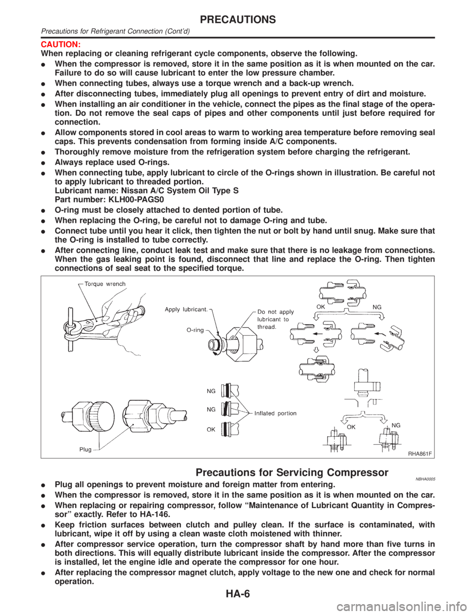
CAUTION:
When replacing or cleaning refrigerant cycle components, observe the following.
IWhen the compressor is removed, store it in the same position as it is when mounted on the car.
Failure to do so will cause lubricant to enter the low pressure chamber.
IWhen connecting tubes, always use a torque wrench and a back-up wrench.
IAfter disconnecting tubes, immediately plug all openings to prevent entry of dirt and moisture.
IWhen installing an air conditioner in the vehicle, connect the pipes as the final stage of the opera-
tion. Do not remove the seal caps of pipes and other components until just before required for
connection.
IAllow components stored in cool areas to warm to working area temperature before removing seal
caps. This prevents condensation from forming inside A/C components.
IThoroughly remove moisture from the refrigeration system before charging the refrigerant.
IAlways replace used O-rings.
IWhen connecting tube, apply lubricant to circle of the O-rings shown in illustration. Be careful not
to apply lubricant to threaded portion.
Lubricant name: Nissan A/C System Oil Type S
Part number: KLH00-PAGS0
IO-ring must be closely attached to dented portion of tube.
IWhen replacing the O-ring, be careful not to damage O-ring and tube.
IConnect tube until you hear it click, then tighten the nut or bolt by hand until snug. Make sure that
the O-ring is installed to tube correctly.
IAfter connecting line, conduct leak test and make sure that there is no leakage from connections.
When the gas leaking point is found, disconnect that line and replace the O-ring. Then tighten
connections of seal seat to the specified torque.
RHA861F
Precautions for Servicing CompressorNBHA0005IPlug all openings to prevent moisture and foreign matter from entering.
IWhen the compressor is removed, store it in the same position as it is when mounted on the car.
IWhen replacing or repairing compressor, follow ªMaintenance of Lubricant Quantity in Compres-
sorº exactly. Refer to HA-146.
IKeep friction surfaces between clutch and pulley clean. If the surface is contaminated, with
lubricant, wipe it off by using a clean waste cloth moistened with thinner.
IAfter compressor service operation, turn the compressor shaft by hand more than five turns in
both directions. This will equally distribute lubricant inside the compressor. After the compressor
is installed, let the engine idle and operate the compressor for one hour.
IAfter replacing the compressor magnet clutch, apply voltage to the new one and check for normal
operation.
PRECAUTIONS
Precautions for Refrigerant Connection (Cont'd)
HA-6
Page 1819 of 2395
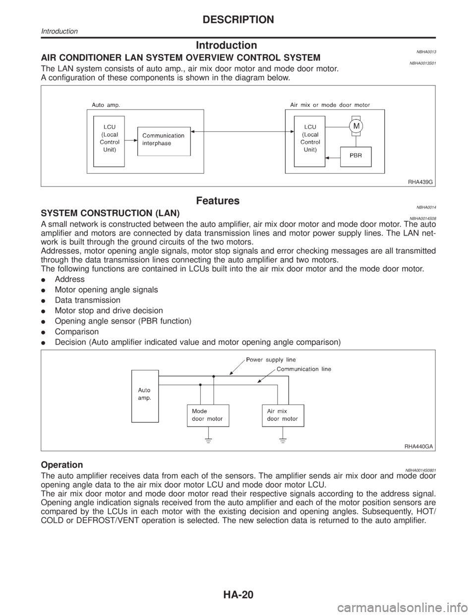
IntroductionNBHA0013AIR CONDITIONER LAN SYSTEM OVERVIEW CONTROL SYSTEMNBHA0013S01The LAN system consists of auto amp., air mix door motor and mode door motor.
A configuration of these components is shown in the diagram below.
RHA439G
FeaturesNBHA0014SYSTEM CONSTRUCTION (LAN)NBHA0014S08A small network is constructed between the auto amplifier, air mix door motor and mode door motor. The auto
amplifier and motors are connected by data transmission lines and motor power supply lines. The LAN net-
work is built through the ground circuits of the two motors.
Addresses, motor opening angle signals, motor stop signals and error checking messages are all transmitted
through the data transmission lines connecting the auto amplifier and two motors.
The following functions are contained in LCUs built into the air mix door motor and the mode door motor.
IAddress
IMotor opening angle signals
IData transmission
IMotor stop and drive decision
IOpening angle sensor (PBR function)
IComparison
IDecision (Auto amplifier indicated value and motor opening angle comparison)
RHA440GA
OperationNBHA0014S0801The auto amplifier receives data from each of the sensors. The amplifier sends air mix door and mode door
opening angle data to the air mix door motor LCU and mode door motor LCU.
The air mix door motor and mode door motor read their respective signals according to the address signal.
Opening angle indication signals received from the auto amplifier and each of the motor position sensors are
compared by the LCUs in each motor with the existing decision and opening angles. Subsequently, HOT/
COLD or DEFROST/VENT operation is selected. The new selection data is returned to the auto amplifier.
DESCRIPTION
Introduction
HA-20
Page 1871 of 2395

RHA464GA
RHA858H
MAIN POWER SUPPLY AND GROUND CIRCUIT CHECKNBHA0037Component DescriptionNBHA0037S01Automatic Amplifier (Auto Amp.)NBHA0037S0101The auto amplifier has a built-in microcomputer which processes
information sent from various sensors needed for air conditioner
operation. The air mix door motor, mode door motor, intake door
motor, blower motor and compressor are then controlled.
The auto amplifier is unitized with control mechanisms. Signals
from various switches and Potentio Temperature Control (PTC) are
directly entered into auto amplifier.
Self-diagnostic functions are also built into auto amplifier to provide
quick check of malfunctions in the auto air conditioner system.
RHA464GA
RHA867H
Potentio Temperature Control (PTC)NBHA0037S0102The PTC is built into the A/C auto amp. or Display & NAVI control
unit. It can be set at an interval of 0.5ÉC (1.0ÉF) in the 18ÉC (65ÉF)
to 32ÉC (85ÉF) temperature range by pushing the temperature but-
ton. The set temperature is digitally displayed.
TROUBLE DIAGNOSES
A/C System (Cont'd)
HA-72
Page 1961 of 2395
A
AAC/V - Wiring diagram ...............................EC-425
ABS - Wiring diagram ....................................BR-37
ABS sensor rotor ........................................AX-6, 19
Absolute pressure sensor ............................EC-158
A/C air flow .....................................................HA-25
A/C component layout ....................................HA-19
A/C compressor clutch removal and
installation .................................................HA-150
A/C compressor precaution..............................HA-6
A/C compressor special service tool..............HA-10
A/C control operation (auto A/C) ....................HA-23
A/C diagnostic work flow (auto A/C) ..............HA-65
A/C HFC134a (R134a) system
precaution .....................................................HA-2
A/C HFC134a (R134a) system service
procedure ..................................................HA-144
A/C HFC134a (R134a) system service
tools.............................................................HA-11
A/C HFC134a system service equip-
ment precaution ............................................HA-7
A/C lubricant (R134a)...................................HA-146
A/C operational check ....................................HA-66
A/C performance chart .................................HA-116
A/C performance test diagnoses ..................HA-114
A/C relay .......................................................HA-110
A/C self-diagnoses (auto A/C)........................HA-44
A/C service data specification ......................HA-160
A/C system description (auto A/C) .................HA-23
A/C trouble diagnoses (auto A/C) ..................HA-27
A/C, A - Wiring diagram ...........................HA-31, 36
Accelerator control system ...............................FE-3
Accelerator wire adjustment .............................FE-3
Actuator lever (Transfer) ...............................TF-120
Air bag ............................................................RS-10
Air bag disposal..............................................RS-22
Air bag precautions ...........................................GI-3
Air bleeding for brake system ..........................BR-8
Air cleaner filter replacement .........................MA-17
Air conditioner cut control ..............................EC-31
Air flow meter - See Mass air flow
sensor .......................................................EC-150
Air mix door control linkage adjustment.........HA-85
Air mix. door motor ................................HA-82, 141
Air spoiler, rear................................................BT-35
All - mode 4WD system ..................................TF-10
Alternator ........................................................SC-28
Ambient sensor ............................................HA-129
Angular tightening application..........................EM-3
Antenna - See Power antenna .....................EL-169
Anti-lock brake system - Wiring
diagram .......................................................BR-37
AP/SEN - Wiring diagram ............................EC-160
ASCD (automatic speed control device) ......EL-221
ASCD - Wiring diagram ................................EL-225
A/T - Wiring diagram - AT - FTS ...................AT-107
A/T - Wiring diagram - AT - MAIN ...................AT-96
A/T - Wiring diagram - AT - PNP/SW............AT-101A/T - Wiring diagram - AT - VSS A/T ............AT-113
A/T control ....................................................EC-440
A/T diagnosis communication line................EC-603
A/T fluid temperature sensor .........................AT-110
A/T self-diagnoses...........................................AT-46
A/T shift lock system .....................................AT-265
A/T shift lock system - Wiring diagram .........AT-266
A/T trouble diagnoses .....................................AT-53
A/T Wiring diagram - AT - ENG SS...............AT-117
A/T Wiring diagram AT - 1ST ........................AT-123
A/T Wiring diagram AT - 2ND .......................AT-129
A/T Wiring diagram AT - 3RD .......................AT-135
A/T Wiring diagram AT - 4TH ........................AT-142
A/T Wiring diagram AT - BA/FTS ..................AT-192
A/T Wiring diagram AT - LPSV .....................AT-164
A/T Wiring diagram AT - NONDTC ...............AT-215
A/T Wiring diagram AT - OVRCSV ...............AT-187
A/T Wiring diagram AT - SSV/A ....................AT-169
A/T Wiring diagram AT - SSV/B ....................AT-173
A/T Wiring diagram AT - TCCSIG .................AT-156
A/T Wiring diagram AT - TCV .......................AT-150
A/T Wiring diagram AT - TPS........................AT-179
A/T Wiring diagram AT - VSSMTR................AT-199
AT/C - Wiring diagram ..................................EC-442
ATP switch.....................................................TF-112
ATP warning lamp .........................................TF-102
Audio .............................................................EL-160
AUDIO - Wiring diagram ...............................EL-162
Audio and A/C control removal and
installation - See Instrument panel .............BT-21
AUT/DP - Wiring diagram .............................EL-191
Auto air conditioner - Wiring diagram ......HA-31, 36
Automatic amplifier...................................HA-40, 72
Automatic drive positioner ............................EL-186
Automatic speed control system - See
ASCD ........................................................EL-221
Automatic transmission fluid
replacement ................................................MA-21
Automatic transmission number ......................GI-43
Auxiliary air control (AAC) valve ..................EC-422
Axle housing (rear) .........................................AX-19
B
Back door ........................................................BT-15
Back door opener - See Back door ................BT-15
Back door trim.................................................BT-34
Back-up lamp ..................................................EL-69
BACK/L - Wiring diagram................................EL-69
Ball joint (front) ...............................................SU-12
Base idle air volume initialiging......................EC-57
Basic inspection ...........................................EC-101
Battery ..............................................................SC-4
Battery/Starting/Charging System
Tester ................................................SC-7, 12, 21
Blower motor ..................................................HA-95
Body alignment ...............................................BT-57
Brake booster .................................................BR-19
Brake control valve (Proportioning
valve)...........................................................BR-11
ALPHABETICAL INDEX
IDX-2
Page 2000 of 2395
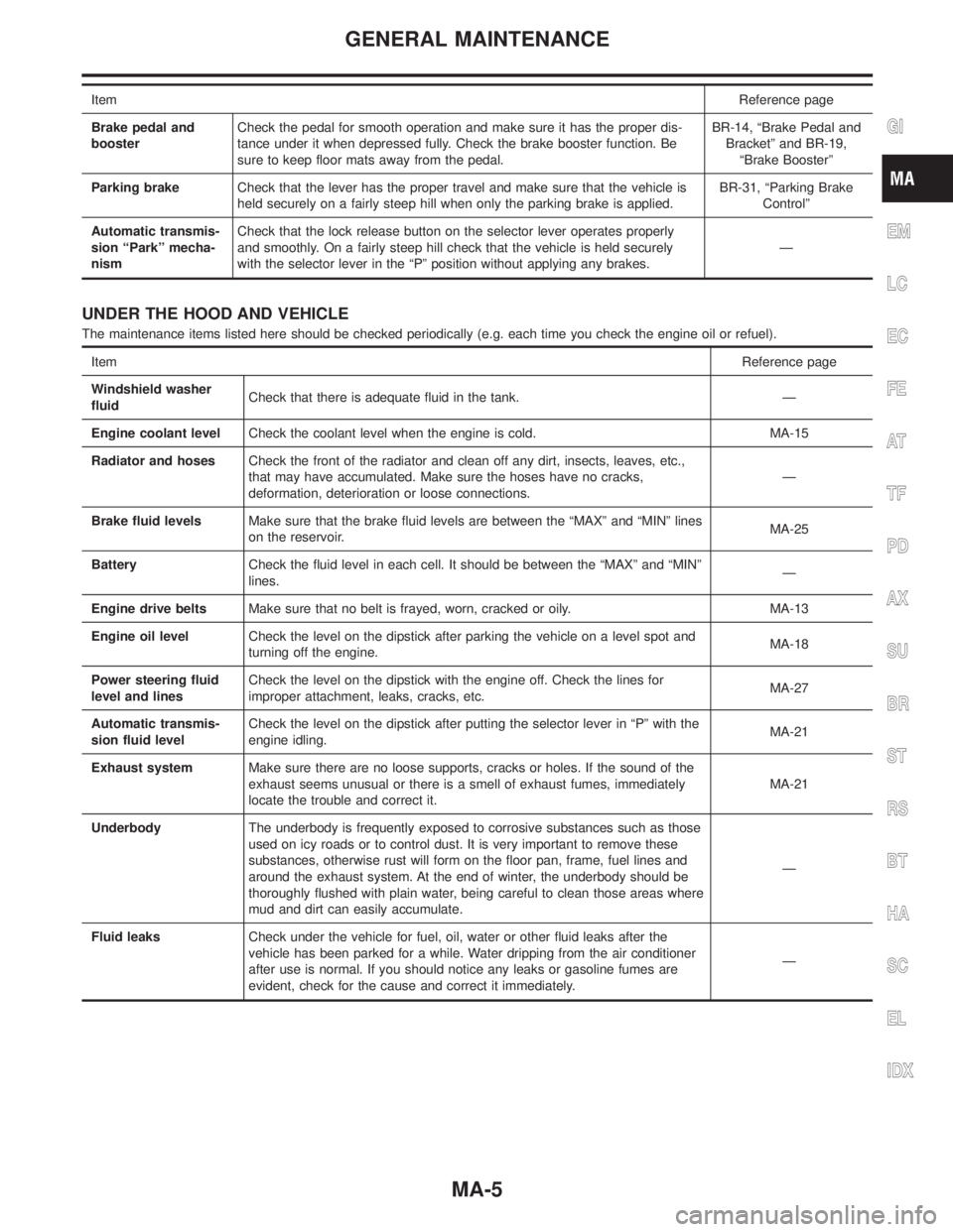
ItemReference page
Brake pedal and
boosterCheck the pedal for smooth operation and make sure it has the proper dis-
tance under it when depressed fully. Check the brake booster function. Be
sure to keep floor mats away from the pedal.BR-14, ªBrake Pedal and
Bracketº and BR-19,
ªBrake Boosterº
Parking brakeCheck that the lever has the proper travel and make sure that the vehicle is
held securely on a fairly steep hill when only the parking brake is applied.BR-31, ªParking Brake
Controlº
Automatic transmis-
sion ªParkº mecha-
nismCheck that the lock release button on the selector lever operates properly
and smoothly. On a fairly steep hill check that the vehicle is held securely
with the selector lever in the ªPº position without applying any brakes.Ð
UNDER THE HOOD AND VEHICLE
The maintenance items listed here should be checked periodically (e.g. each time you check the engine oil or refuel).
ItemReference page
Windshield washer
fluidCheck that there is adequate fluid in the tank. Ð
Engine coolant levelCheck the coolant level when the engine is cold. MA-15
Radiator and hosesCheck the front of the radiator and clean off any dirt, insects, leaves, etc.,
that may have accumulated. Make sure the hoses have no cracks,
deformation, deterioration or loose connections.Ð
Brake fluid levelsMake sure that the brake fluid levels are between the ªMAXº and ªMINº lines
on the reservoir.MA-25
BatteryCheck the fluid level in each cell. It should be between the ªMAXº and ªMINº
lines.Ð
Engine drive beltsMake sure that no belt is frayed, worn, cracked or oily. MA-13
Engine oil levelCheck the level on the dipstick after parking the vehicle on a level spot and
turning off the engine.MA-18
Power steering fluid
level and linesCheck the level on the dipstick with the engine off. Check the lines for
improper attachment, leaks, cracks, etc.MA-27
Automatic transmis-
sion fluid levelCheck the level on the dipstick after putting the selector lever in ªPº with the
engine idling.MA-21
Exhaust systemMake sure there are no loose supports, cracks or holes. If the sound of the
exhaust seems unusual or there is a smell of exhaust fumes, immediately
locate the trouble and correct it.MA-21
UnderbodyThe underbody is frequently exposed to corrosive substances such as those
used on icy roads or to control dust. It is very important to remove these
substances, otherwise rust will form on the floor pan, frame, fuel lines and
around the exhaust system. At the end of winter, the underbody should be
thoroughly flushed with plain water, being careful to clean those areas where
mud and dirt can easily accumulate.Ð
Fluid leaksCheck under the vehicle for fuel, oil, water or other fluid leaks after the
vehicle has been parked for a while. Water dripping from the air conditioner
after use is normal. If you should notice any leaks or gasoline fumes are
evident, check for the cause and correct it immediately.Ð
GI
EM
LC
EC
FE
AT
TF
PD
AX
SU
BR
ST
RS
BT
HA
SC
EL
IDX
GENERAL MAINTENANCE
MA-5
Page 2008 of 2395

Checking Drive BeltsNBMA0010
SMA091D
1. Inspect belt for cracks, fraying, wear and oil. If necessary,
replace.
2. Inspect drive belt deflection or tension at a point on the belt
midway between pulleys.
3. Check belt tension using belt tension gauge (BT3373-F or
equivalent).
Inspect drive belt deflection or tension when engine is cold.
Adjust if belt deflections exceed the limit or if belt tension is
not within specifications.
Belt deflection and tension
Deflection adjustment Unit: mm (in) Tension adjustment *1 Unit: N (kg, lb)
Used belt
New beltUsed belt
New belt
Limit After adjustment Limit After adjustment
Alternator
Power steering
oil pump
Fan7 (0.28)4-5
(0.16 - 0.20)3.5 - 4.5
(0.138 - 0.177)294 (30, 66)730 - 818 (74.4 -
83.5, 164 - 184)838 - 926 (85.4 -
94.5, 188 - 208)
Air conditioner
compressor12 (0.47)9-10
(0.35 - 0.39)8-9
(0.31 - 0.35)196 (20, 44)348 - 436 (35.5 -
44.5, 78 - 98)470 - 559 (47.9 -
57.0, 106 - 126)
Applied pushing
force98 N (10 kg, 22 lb) Ð
*1 If belt tension gauge cannot be installed at check points shown, check drive belt tension at a different location on the belt.
GI
EM
LC
EC
FE
AT
TF
PD
AX
SU
BR
ST
RS
BT
HA
SC
EL
IDX
ENGINE MAINTENANCE
Checking Drive Belts
MA-13