Page 1420 of 2395

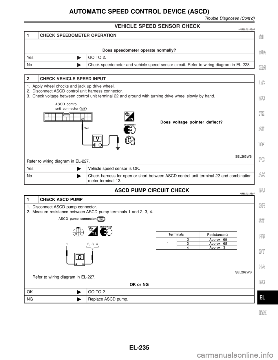
VEHICLE SPEED SENSOR CHECK=NBEL0218S06
1 CHECK SPEEDOMETER OPERATION
Does speedometer operate normally?
Ye s©GO TO 2.
No©Check speedometer and vehicle speed sensor circuit. Refer to wiring diagram in EL-228.
2 CHECK VEHICLE SPEED INPUT
1. Apply wheel chocks and jack up drive wheel.
2. Disconnect ASCD control unit harness connector.
3. Check voltage between control unit terminal 22 and ground with turning drive wheel slowly by hand.
SEL263WB
Refer to wiring diagram in EL-227.
Ye s©Vehicle speed sensor is OK.
No©Check harness for open or short between ASCD control unit terminal 22 and combination
meter terminal 13.
ASCD PUMP CIRCUIT CHECKNBEL0218S07
1 CHECK ASCD PUMP
1. Disconnect ASCD pump connector.
2. Measure resistance between ASCD pump terminals 1 and 2, 3, 4.
SEL262WB
Refer to wiring diagram in EL-227.
OK or NG
OK©GO TO 2.
NG©Replace ASCD pump.
GI
MA
EM
LC
EC
FE
AT
TF
PD
AX
SU
BR
ST
RS
BT
HA
SC
IDX
AUTOMATIC SPEED CONTROL DEVICE (ASCD)
Trouble Diagnoses (Cont'd)
EL-235
Page 1430 of 2395
Wiring Diagram Ð WINDOW ÐNBEL0104
MEL008O
GI
MA
EM
LC
EC
FE
AT
TF
PD
AX
SU
BR
ST
RS
BT
HA
SC
IDX
POWER WINDOW
Wiring Diagram Ð WINDOW Ð
EL-245
Page 1431 of 2395
MEL844L
POWER WINDOW
Wiring Diagram Ð WINDOW Ð (Cont'd)
EL-246
Page 1432 of 2395
MEL845L
GI
MA
EM
LC
EC
FE
AT
TF
PD
AX
SU
BR
ST
RS
BT
HA
SC
IDX
POWER WINDOW
Wiring Diagram Ð WINDOW Ð (Cont'd)
EL-247
Page 1433 of 2395
MEL846L
POWER WINDOW
Wiring Diagram Ð WINDOW Ð (Cont'd)
EL-248
Page 1434 of 2395
MEL847L
GI
MA
EM
LC
EC
FE
AT
TF
PD
AX
SU
BR
ST
RS
BT
HA
SC
IDX
POWER WINDOW
Wiring Diagram Ð WINDOW Ð (Cont'd)
EL-249
Page 1441 of 2395
Wiring Diagram Ð D/LOCK ÐNBEL0109FIG. 1NBEL0109S01
MEL848L
POWER DOOR LOCK
Wiring Diagram Ð D/LOCK Ð
EL-256
Page 1442 of 2395
FIG. 2NBEL0109S02
MEL849L
GI
MA
EM
LC
EC
FE
AT
TF
PD
AX
SU
BR
ST
RS
BT
HA
SC
IDX
POWER DOOR LOCK
Wiring Diagram Ð D/LOCK Ð (Cont'd)
EL-257