2001 INFINITI QX4 service indicator
[x] Cancel search: service indicatorPage 1555 of 2395
NOTE:
After replacing IVCS unit, set up the replaced IVCS unit. Refer
to ªSystem Setting (When IVCS Unit is Replaced.)º in EL-381.
SYMPTOM CHART 2 (BASED ON SYMPTOM)NBEL0184S04Before referencing this chart, confirm the operation of the indicator
lamps. Refer to ªPRELIMINARY CHECKº in EL-369. If the indica-
tors show the system is malfunctioning, perform the self-diagnosis
using CONSULT-II.
Symptom Diagnoses/service procedure Reference page
ªMAYDAYº, ªINFORMATIONº, ªRE-DIALº,
ªNO SERVICEº indicator lamps do not illu-
minate when ignition switch is turned to ON
position. (Bulb check is NG.)1. Power supply and ground circuit for IVCS unit check EL-371
2. Indicator lamps check EL-372
Mayday/Information call does not operate.1. IVCS switch check EL-373
2. INFINITI Communicator operation check in demonstration
modeEL-379
Remote door unlocking function does not
operate.1. Back door handle switch check EL-374
2. Remote door unlock function check EL-374
3. INFINITI Communicator operation check in demonstration
modeEL-379
Stolen vehicle tracking function does not
operate.1. Stolen vehicle tracking setting check
(Check whether the function is disabled or not.)EL-375
2. INFINITI Communicator operation check in demonstration
modeEL-379
Alarm notification function does not oper-
ate.1. Alarm notification setting check
(Check whether the function is disabled or not.)EL-375
2. INFINITI Communicator operation check in demonstration
modeEL-379
Hands free telephone cannot be operated
by using steering switch.
(Cellular phone operates properly by using
handset.)1. Telephone steering switch check EL-377
No sounds related to the telephone are
heard from Front RH speaker. (If the audio
does not operate properly, check the audio
system.)1. Check harness for open or short between IVCS unit and
audio unit.Ð
The ªNO SERVICEº indicator lamp is not
turned off. (Even if a contract with tele-
phone carrier has not been made, the indi-
cator lamp remains illuminated.)1. Make sure the vehicle is in an area with cellular service. Ð
2. Check cellular phone antenna feeder cable connection. Ð
Cellular phone does not operate properly.1. Check hand set connector connection. Ð
2. Check hand set. Ð
No sound is transmitted to the other party
by hands free telephone.1. Check harness for open or short between IVCS unit and
microphone.Ð
2. Replace microphone. (IVCS switch assembly) Ð
INFINITI COMMUNICATOR (IVCS)
Trouble Diagnoses (Cont'd)
EL-370
Page 1562 of 2395
TELEPHONE STEERING SWITCH CHECK=NBEL0184S14
1 CHECK POWER SUPPLY FOR STEERING SWITCH
Check power supply for steering switch.
Does horn work?
Ye s©Check the following.
I10A fuse (No. 54, located in fuse and fusible link box)
IHorn relay
IHarness for open or short
No©GO TO 2.
2 CHECK STEERING SWITCH SUB-HARNESS
1. Remove driver's air bag module. For removal procedure, refer to RS section.
2. Check steering switch sub-harness for open or short and ground screw.
For details of the harness circuit, refer to ªSTEERING SWITCHº, EL-30.
OK or NG
OK©Check harness for open or short between telephone steering switch and IVCS unit. If the
circuit is OK, replace telephone steering switch.
NG©Replace or repair the harness.
Trouble Diagnoses for Intermittent IncidentNBEL0185DESCRIPTIONNBEL0185S01An intermittent incident may be occurring if all of the following conditions exist.
IBoth ªMAYDAYº emergency and ªINFORMATIONº indicators have shown that the system is malfunction-
ing.
ICONSULT-II self-diagnosis result screen indicates a trouble code with ªTIME=1orgreaterº.
IThe INFINITI Communicator system has not been previously serviced.
To find out the cause of a malfunction, follow the procedures shown below.
GI
MA
EM
LC
EC
FE
AT
TF
PD
AX
SU
BR
ST
RS
BT
HA
SC
IDX
INFINITI COMMUNICATOR (IVCS)
Trouble Diagnoses (Cont'd)
EL-377
Page 1565 of 2395
SEL528V
4. Touch ªBACKº key of CONSULT-II until ªSELECT SYSTEMº
appears, then turn off CONSULT-II.
5. Turn ignition switch to the OFF position.
6. Disconnect CONSULT-II DDL connector.
7. Start the engine.
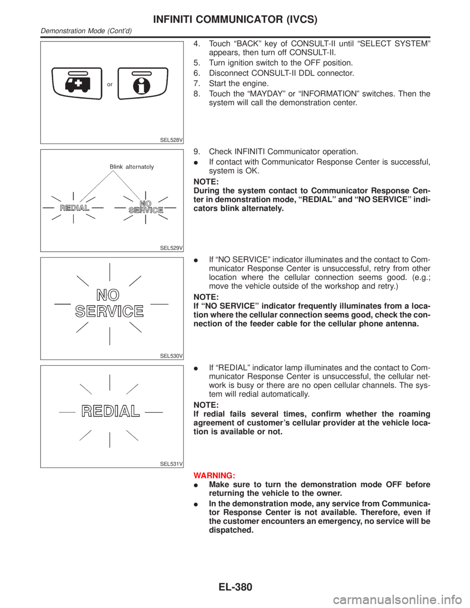
8. Touch the ªMAYDAYº or ªINFORMATIONº switches. Then the
system will call the demonstration center.
SEL529V
9. Check INFINITI Communicator operation.
IIf contact with Communicator Response Center is successful,
system is OK.
NOTE:
During the system contact to Communicator Response Cen-
ter in demonstration mode, ªREDIALº and ªNO SERVICEº indi-
cators blink alternately.
SEL530V
IIf ªNO SERVICEº indicator illuminates and the contact to Com-
municator Response Center is unsuccessful, retry from other
location where the cellular connection seems good. (e.g.;
move the vehicle outside of the workshop and retry.)
NOTE:
If ªNO SERVICEº indicator frequently illuminates from a loca-
tion where the cellular connection seems good, check the con-
nection of the feeder cable for the cellular phone antenna.
SEL531V
IIf ªREDIALº indicator lamp illuminates and the contact to Com-
municator Response Center is unsuccessful, the cellular net-
work is busy or there are no open cellular channels. The sys-
tem will redial automatically.
NOTE:
If redial fails several times, confirm whether the roaming
agreement of customer's cellular provider at the vehicle loca-
tion is available or not.
WARNING:
IMake sure to turn the demonstration mode OFF before
returning the vehicle to the owner.
IIn the demonstration mode, any service from Communica-
tor Response Center is not available. Therefore, even if
the customer encounters an emergency, no service will be
dispatched.
INFINITI COMMUNICATOR (IVCS)
Demonstration Mode (Cont'd)
EL-380
Page 1723 of 2395
SEM621F
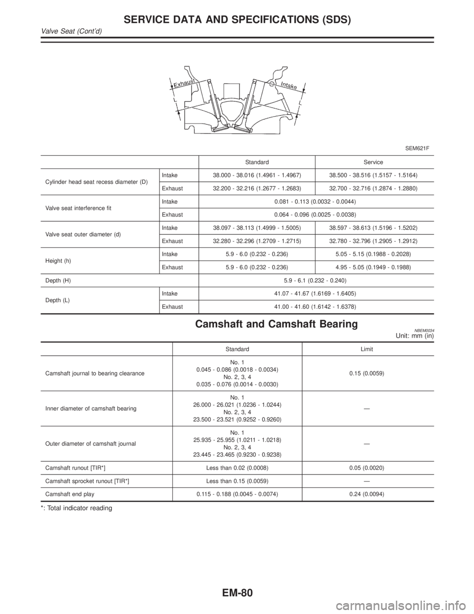
Standard Service
Cylinder head seat recess diameter (D)Intake 38.000 - 38.016 (1.4961 - 1.4967) 38.500 - 38.516 (1.5157 - 1.5164)
Exhaust 32.200 - 32.216 (1.2677 - 1.2683) 32.700 - 32.716 (1.2874 - 1.2880)
Valve seat interference fitIntake 0.081 - 0.113 (0.0032 - 0.0044)
Exhaust 0.064 - 0.096 (0.0025 - 0.0038)
Valve seat outer diameter (d)Intake 38.097 - 38.113 (1.4999 - 1.5005) 38.597 - 38.613 (1.5196 - 1.5202)
Exhaust 32.280 - 32.296 (1.2709 - 1.2715) 32.780 - 32.796 (1.2905 - 1.2912)
Height (h)Intake 5.9 - 6.0 (0.232 - 0.236) 5.05 - 5.15 (0.1988 - 0.2028)
Exhaust 5.9 - 6.0 (0.232 - 0.236) 4.95 - 5.05 (0.1949 - 0.1988)
Depth (H)5.9 - 6.1 (0.232 - 0.240)
Depth (L)Intake 41.07 - 41.67 (1.6169 - 1.6405)
Exhaust 41.00 - 41.60 (1.6142 - 1.6378)
Camshaft and Camshaft BearingNBEM0034Unit: mm (in)
Standard Limit
Camshaft journal to bearing clearanceNo. 1
0.045 - 0.086 (0.0018 - 0.0034)
No. 2, 3, 4
0.035 - 0.076 (0.0014 - 0.0030)0.15 (0.0059)
Inner diameter of camshaft bearingNo. 1
26.000 - 26.021 (1.0236 - 1.0244)
No. 2, 3, 4
23.500 - 23.521 (0.9252 - 0.9260)Ð
Outer diameter of camshaft journalNo. 1
25.935 - 25.955 (1.0211 - 1.0218)
No. 2, 3, 4
23.445 - 23.465 (0.9230 - 0.9238)Ð
Camshaft runout [TIR*] Less than 0.02 (0.0008) 0.05 (0.0020)
Camshaft sprocket runout [TIR*] Less than 0.15 (0.0059) Ð
Camshaft end play 0.115 - 0.188 (0.0045 - 0.0074) 0.24 (0.0094)
*: Total indicator reading
SERVICE DATA AND SPECIFICATIONS (SDS)
Valve Seat (Cont'd)
EM-80
Page 1727 of 2395
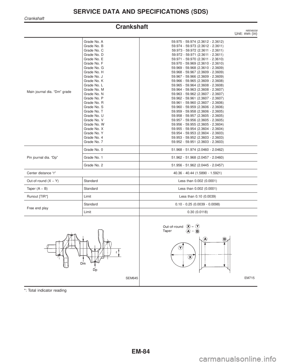
CrankshaftNBEM0038Unit: mm (in)
Main journal dia. ªDmº gradeGrade No. A
Grade No. B
Grade No. C
Grade No. D
Grade No. E
Grade No. F
Grade No. G
Grade No. H
Grade No. J
Grade No. K
Grade No. L
Grade No. M
Grade No. N
Grade No. P
Grade No. R
Grade No. S
Grade No. T
Grade No. U
Grade No. V
Grade No. W
Grade No. X
Grade No. Y
Grade No. 4
Grade No. 759.975 - 59.974 (2.3612 - 2.3612)
59.974 - 59.973 (2.3612 - 2.3611)
59.973 - 59.972 (2.3611 - 2.3611)
59.972 - 59.971 (2.3611 - 2.3611)
59.971 - 59.970 (2.3611 - 2.3610)
59.970 - 59.969 (2.3610 - 2.3610)
59.969 - 59.968 (2.3610 - 2.3609)
59.968 - 59.967 (2.3609 - 2.3609)
59.967 - 59.966 (2.3609 - 2.3609)
59.966 - 59.965 (2.3609 - 2.3608)
59.965 - 59.964 (2.3608 - 2.3608)
59.964 - 59.963 (2.3608 - 2.3607)
59.963 - 59.962 (2.3607 - 2.3607)
59.962 - 59.961 (2.3607 - 2.3607)
59.961 - 59.960 (2.3607 - 2.3606)
59.960 - 59.959 (2.3606 - 2.3606)
59.959 - 59.958 (2.3606 - 2.3605)
59.958 - 59.957 (2.3605 - 2.3605)
59.957 - 59.956 (2.3605 - 2.3605)
59.956 - 59.955 (2.3605 - 2.3604)
59.955 - 59.954 (2.3604 - 2.3604)
59.954 - 59.953 (2.3604 - 2.3603)
59.953 - 59.952 (2.3603 - 2.3603)
59.952 - 59.951 (2.3603 - 2.3603)
Pin journal dia. ªDpºGrade No. 0 51.968 - 51.974 (2.0460 - 2.0462)
Grade No. 1 51.962 - 51.968 (2.0457 - 2.0460)
Grade No. 2 51.956 - 51.962 (2.0445 - 2.0457)
Center distance ªrº40.36 - 40.44 (1.5890 - 1.5921)
Out-of-round (X þ Y) Standard Less than 0.002 (0.0001)
Taper (A þ B) Standard Less than 0.002 (0.0001)
Runout [TIR*] Limit Less than 0.10 (0.0039)
Free end playStandard 0.10 - 0.25 (0.0039 - 0.0098)
Limit 0.30 (0.0118)
SEM645EM715
*: Total indicator reading
SERVICE DATA AND SPECIFICATIONS (SDS)
Crankshaft
EM-84
Page 1729 of 2395
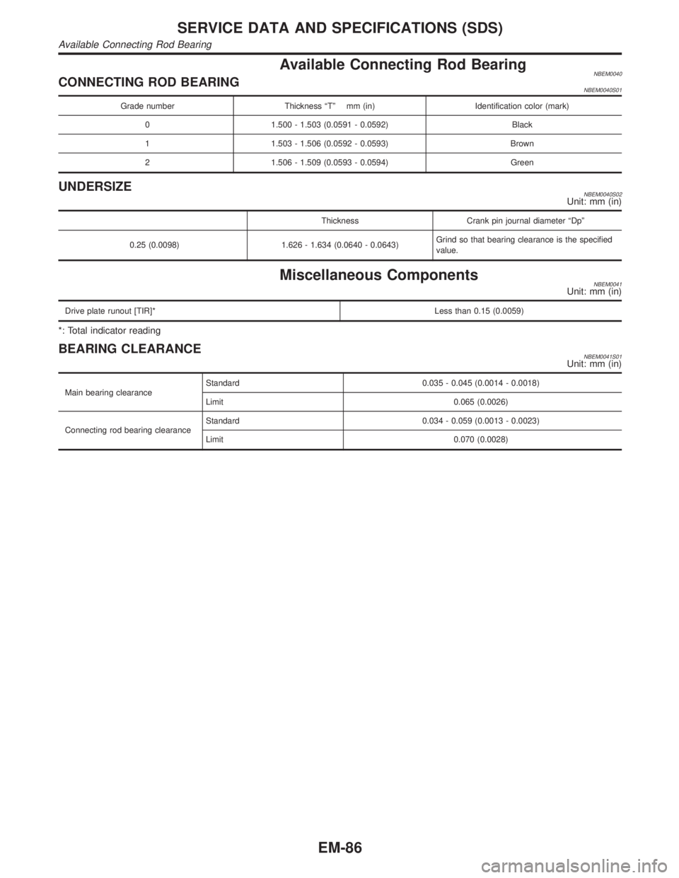
Available Connecting Rod BearingNBEM0040CONNECTING ROD BEARINGNBEM0040S01
Grade number Thickness ªTº mm (in) Identification color (mark)
0 1.500 - 1.503 (0.0591 - 0.0592) Black
1 1.503 - 1.506 (0.0592 - 0.0593) Brown
2 1.506 - 1.509 (0.0593 - 0.0594) Green
UNDERSIZENBEM0040S02Unit: mm (in)
Thickness Crank pin journal diameter ªDpº
0.25 (0.0098) 1.626 - 1.634 (0.0640 - 0.0643)Grind so that bearing clearance is the specified
value.
Miscellaneous ComponentsNBEM0041Unit: mm (in)
Drive plate runout [TIR]*Less than 0.15 (0.0059)
*: Total indicator reading
BEARING CLEARANCENBEM0041S01Unit: mm (in)
Main bearing clearanceStandard 0.035 - 0.045 (0.0014 - 0.0018)
Limit 0.065 (0.0026)
Connecting rod bearing clearanceStandard 0.034 - 0.059 (0.0013 - 0.0023)
Limit 0.070 (0.0028)
SERVICE DATA AND SPECIFICATIONS (SDS)
Available Connecting Rod Bearing
EM-86
Page 1749 of 2395
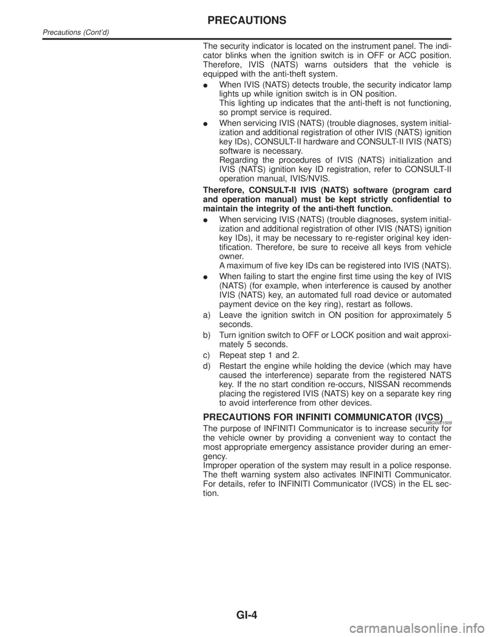
The security indicator is located on the instrument panel. The indi-
cator blinks when the ignition switch is in OFF or ACC position.
Therefore, IVIS (NATS) warns outsiders that the vehicle is
equipped with the anti-theft system.
IWhen IVIS (NATS) detects trouble, the security indicator lamp
lights up while ignition switch is in ON position.
This lighting up indicates that the anti-theft is not functioning,
so prompt service is required.
IWhen servicing IVIS (NATS) (trouble diagnoses, system initial-
ization and additional registration of other IVIS (NATS) ignition
key IDs), CONSULT-II hardware and CONSULT-II IVIS (NATS)
software is necessary.
Regarding the procedures of IVIS (NATS) initialization and
IVIS (NATS) ignition key ID registration, refer to CONSULT-II
operation manual, IVIS/NVIS.
Therefore, CONSULT-II IVIS (NATS) software (program card
and operation manual) must be kept strictly confidential to
maintain the integrity of the anti-theft function.
IWhen servicing IVIS (NATS) (trouble diagnoses, system initial-
ization and additional registration of other IVIS (NATS) ignition
key IDs), it may be necessary to re-register original key iden-
tification. Therefore, be sure to receive all keys from vehicle
owner.
A maximum of five key IDs can be registered into IVIS (NATS).
IWhen failing to start the engine first time using the key of IVIS
(NATS) (for example, when interference is caused by another
IVIS (NATS) key, an automated full road device or automated
payment device on the key ring), restart as follows.
a) Leave the ignition switch in ON position for approximately 5
seconds.
b) Turn ignition switch to OFF or LOCK position and wait approxi-
mately 5 seconds.
c) Repeat step 1 and 2.
d) Restart the engine while holding the device (which may have
caused the interference) separate from the registered NATS
key. If the no start condition re-occurs, NISSAN recommends
placing the registered IVIS (NATS) key on a separate key ring
to avoid interference from other devices.
PRECAUTIONS FOR INFINITI COMMUNICATOR (IVCS)NBGI0001S09The purpose of INFINITI Communicator is to increase security for
the vehicle owner by providing a convenient way to contact the
most appropriate emergency assistance provider during an emer-
gency.
Improper operation of the system may result in a police response.
The theft warning system also activates INFINITI Communicator.
For details, refer to INFINITI Communicator (IVCS) in the EL sec-
tion.
PRECAUTIONS
Precautions (Cont'd)
GI-4
Page 1798 of 2395
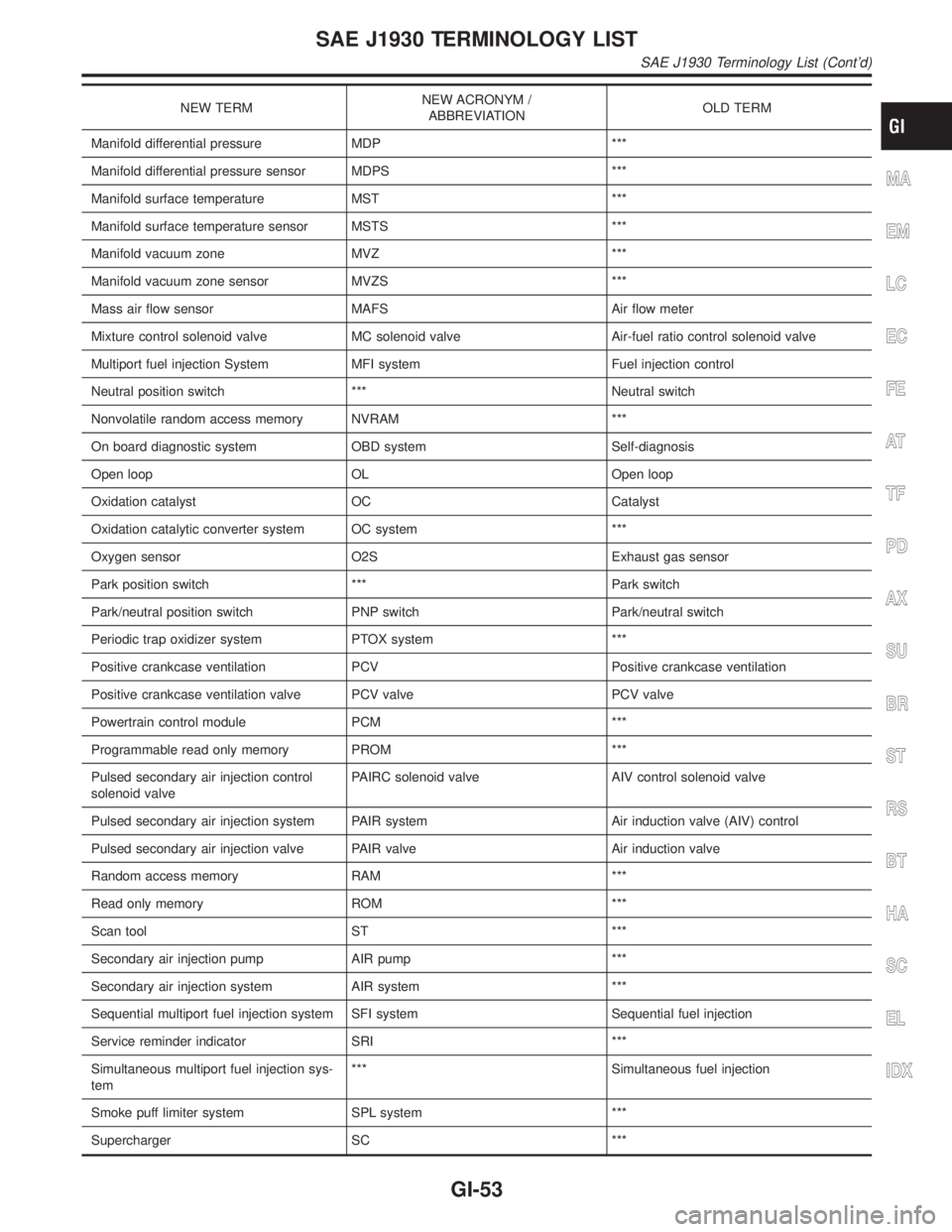
NEW TERMNEW ACRONYM /
ABBREVIATIONOLD TERM
Manifold differential pressure MDP ***
Manifold differential pressure sensor MDPS ***
Manifold surface temperature MST ***
Manifold surface temperature sensor MSTS ***
Manifold vacuum zone MVZ ***
Manifold vacuum zone sensor MVZS ***
Mass air flow sensor MAFS Air flow meter
Mixture control solenoid valve MC solenoid valve Air-fuel ratio control solenoid valve
Multiport fuel injection System MFI system Fuel injection control
Neutral position switch *** Neutral switch
Nonvolatile random access memory NVRAM ***
On board diagnostic system OBD system Self-diagnosis
Open loop OL Open loop
Oxidation catalyst OC Catalyst
Oxidation catalytic converter system OC system ***
Oxygen sensor O2S Exhaust gas sensor
Park position switch *** Park switch
Park/neutral position switch PNP switch Park/neutral switch
Periodic trap oxidizer system PTOX system ***
Positive crankcase ventilation PCV Positive crankcase ventilation
Positive crankcase ventilation valve PCV valve PCV valve
Powertrain control module PCM ***
Programmable read only memory PROM ***
Pulsed secondary air injection control
solenoid valvePAIRC solenoid valve AIV control solenoid valve
Pulsed secondary air injection system PAIR system Air induction valve (AIV) control
Pulsed secondary air injection valve PAIR valve Air induction valve
Random access memory RAM ***
Read only memory ROM ***
Scan tool ST ***
Secondary air injection pump AIR pump ***
Secondary air injection system AIR system ***
Sequential multiport fuel injection system SFI system Sequential fuel injection
Service reminder indicator SRI ***
Simultaneous multiport fuel injection sys-
tem*** Simultaneous fuel injection
Smoke puff limiter system SPL system ***
Supercharger SC ***
MA
EM
LC
EC
FE
AT
TF
PD
AX
SU
BR
ST
RS
BT
HA
SC
EL
IDX
SAE J1930 TERMINOLOGY LIST
SAE J1930 Terminology List (Cont'd)
GI-53