2001 INFINITI QX4 cruise control
[x] Cancel search: cruise controlPage 603 of 2395
![INFINITI QX4 2001 Factory Service Manual For normal acceleration in low altitude areas
[less than 1,219 m (4,000 ft)]:For quick acceleration in low altitude
areas and high altitude areas
[over 1,219 m (4,000 ft)]:
Gear changeACCEL shift poin INFINITI QX4 2001 Factory Service Manual For normal acceleration in low altitude areas
[less than 1,219 m (4,000 ft)]:For quick acceleration in low altitude
areas and high altitude areas
[over 1,219 m (4,000 ft)]:
Gear changeACCEL shift poin](/manual-img/42/57027/w960_57027-602.png)
For normal acceleration in low altitude areas
[less than 1,219 m (4,000 ft)]:For quick acceleration in low altitude
areas and high altitude areas
[over 1,219 m (4,000 ft)]:
Gear changeACCEL shift point
km/h (MPH)CRUISE shift point
km/h (MPH)km/h (MPH)
1st to 2nd 21 (13) 21 (13) 24 (15)
2nd to 3rd 37 (23) 26 (16) 40 (25)
3rd to 4th 53 (33) 44 (27) 64 (40)
4th to 5th 63 (39) 58 (36) 72 (45)
Suggested Maximum Speed in Each Gear
Downshift to a lower gear if the engine is not running smoothly, or if you need to accelerate.
Do not exceed the maximum suggested speed (shown below) in any gear. For level road driving, use the
highest gear suggested for that speed. Always observe posted speed limits and drive according to the road
conditions to ensure safe operation. Do not over-rev the engine when shifting to a lower gear as it may cause
engine damage or loss of vehicle control.
Gear km/h (MPH)
1st 50 (30)
2nd 89 (55)
3rd 128 (80)
4th Ð
5th Ð
TEST VALUE AND TEST LIMIT (GST ONLY Ð NOT APPLICABLE TO CONSULT-II)NBEC0031S04The following is the information specified in Mode 6 of SAE J1979.
The test value is a parameter used to determine whether a system/circuit diagnostic test is ªOKº or ªNGº while
being monitored by the ECM during self-diagnosis. The test limit is a reference value which is specified as the
maximum or minimum value and is compared with the test value being monitored.
Items for which these data (test value and test limit) are displayed are the same as SRT code items (30 test
items).
These data (test value and test limit) are specified by Test ID (TID) and Component ID (CID) and can be dis-
played on the GST screen.
X: Applicable Ð: Not applicable
SRT item Self-diagnostic test itemTest value (GST display)
Test limit Application
TID CID
C ATA LY S TThree way catalyst function
(Right bank)01H 01H Max. X
Three way catalyst function
(Left bank)03H 02H Max. X
EVAP SYSTEMEVAP control system
(Small leak)05H 03H Max. X
EVAP control system purge flow
monitoring06H 83H Min. X
ON BOARD DIAGNOSTIC SYSTEM DESCRIPTION
Emission-related Diagnostic Information (Cont'd)
EC-68
Page 1407 of 2395
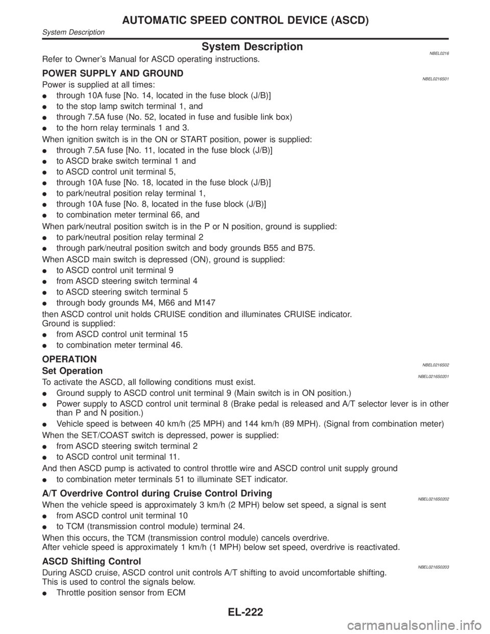
System DescriptionNBEL0216Refer to Owner's Manual for ASCD operating instructions.
POWER SUPPLY AND GROUNDNBEL0216S01Power is supplied at all times:
Ithrough 10A fuse [No. 14, located in the fuse block (J/B)]
Ito the stop lamp switch terminal 1, and
Ithrough 7.5A fuse (No. 52, located in fuse and fusible link box)
Ito the horn relay terminals 1 and 3.
When ignition switch is in the ON or START position, power is supplied:
Ithrough 7.5A fuse [No. 11, located in the fuse block (J/B)]
Ito ASCD brake switch terminal 1 and
Ito ASCD control unit terminal 5,
Ithrough 10A fuse [No. 18, located in the fuse block (J/B)]
Ito park/neutral position relay terminal 1,
Ithrough 10A fuse [No. 8, located in the fuse block (J/B)]
Ito combination meter terminal 66, and
When park/neutral position switch is in the P or N position, ground is supplied:
Ito park/neutral position relay terminal 2
Ithrough park/neutral position switch and body grounds B55 and B75.
When ASCD main switch is depressed (ON), ground is supplied:
Ito ASCD control unit terminal 9
Ifrom ASCD steering switch terminal 4
Ito ASCD steering switch terminal 5
Ithrough body grounds M4, M66 and M147
then ASCD control unit holds CRUISE condition and illuminates CRUISE indicator.
Ground is supplied:
Ifrom ASCD control unit terminal 15
Ito combination meter terminal 46.
OPERATIONNBEL0216S02Set OperationNBEL0216S0201To activate the ASCD, all following conditions must exist.
IGround supply to ASCD control unit terminal 9 (Main switch is in ON position.)
IPower supply to ASCD control unit terminal 8 (Brake pedal is released and A/T selector lever is in other
than P and N position.)
IVehicle speed is between 40 km/h (25 MPH) and 144 km/h (89 MPH). (Signal from combination meter)
When the SET/COAST switch is depressed, power is supplied:
Ifrom ASCD steering switch terminal 2
Ito ASCD control unit terminal 11.
And then ASCD pump is activated to control throttle wire and ASCD control unit supply ground
Ito combination meter terminals 51 to illuminate SET indicator.
A/T Overdrive Control during Cruise Control DrivingNBEL0216S0202When the vehicle speed is approximately 3 km/h (2 MPH) below set speed, a signal is sent
Ifrom ASCD control unit terminal 10
Ito TCM (transmission control module) terminal 24.
When this occurs, the TCM (transmission control module) cancels overdrive.
After vehicle speed is approximately 1 km/h (1 MPH) below set speed, overdrive is reactivated.
ASCD Shifting ControlNBEL0216S0203During ASCD cruise, ASCD control unit controls A/T shifting to avoid uncomfortable shifting.
This is used to control the signals below.
IThrottle position sensor from ECM
AUTOMATIC SPEED CONTROL DEVICE (ASCD)
System Description
EL-222
Page 1408 of 2395
IA/T shift solenoid valve A
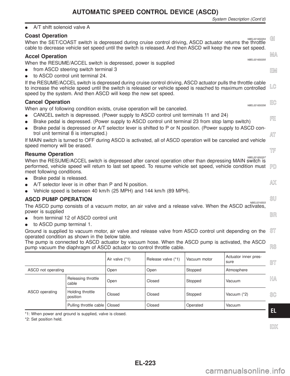
Coast OperationNBEL0216S0204When the SET/COAST switch is depressed during cruise control driving, ASCD actuator returns the throttle
cable to decrease vehicle set speed until the switch is released. And then ASCD will keep the new set speed.
Accel OperationNBEL0216S0205When the RESUME/ACCEL switch is depressed, power is supplied
Ifrom ASCD steering switch terminal 3
Ito ASCD control unit terminal 24.
If the RESUME/ACCEL switch is depressed during cruise control driving, ASCD actuator pulls the throttle cable
to increase the vehicle speed until the switch is released or vehicle speed is reached to maximum controlled
speed by the system. And then ASCD will keep the new set speed.
Cancel OperationNBEL0216S0206When any of following condition exists, cruise operation will be canceled.
ICANCEL switch is depressed. (Power supply to ASCD control unit terminals 11 and 24)
IBrake pedal is depressed. (Power supply to ASCD control unit terminal 23 from stop lamp switch)
IBrake pedal is depressed or A/T selector lever is shifted to P or N position. (Power supply to ASCD con-
trol unit terminal 8 is interrupted.)
If MAIN switch is turned to OFF during ASCD is activated, all of ASCD operation will be canceled and vehicle
speed memory will be erased.
Resume OperationNBEL0216S0207When the RESUME/ACCEL switch is depressed after cancel operation other than depressing MAIN switch is
performed, vehicle speed will return to last set speed. To resume vehicle set speed, vehicle condition must
meet following conditions.
IBrake pedal is released.
IA/T selector lever is in other than P and N position.
IVehicle speed is between 40 km/h (25 MPH) and 144 km/h (89 MPH).
ASCD PUMP OPERATIONNBEL0216S03The ASCD pump consists of a vacuum motor, an air valve and a release valve. When the ASCD activates,
power is supplied
Ifrom terminal 12 of ASCD control unit
Ito ASCD pump terminal 1.
Ground is supplied to vacuum motor, air valve and release valve from ASCD control unit depending on the
operated condition as shown in the below table.
The pump is connected to ASCD actuator by vacuum hose. When the ASCD pump is activated, the ASCD
pump vacuum the diaphragm of ASCD actuator to control throttle cable.
Air valve (*1) Release valve (*1) Vacuum motorActuator inner pres-
sure
ASCD not operating Open Open Stopped Atmosphere
ASCD operatingReleasing throttle
cableOpen Closed Stopped Vacuum
Holding throttle
positionClosed Closed Stopped Vacuum (*2)
Pulling throttle cable Closed Closed Operated Vacuum
*1: When power and ground is supplied, valve is closed.
*2: Set position held.
GI
MA
EM
LC
EC
FE
AT
TF
PD
AX
SU
BR
ST
RS
BT
HA
SC
IDX
AUTOMATIC SPEED CONTROL DEVICE (ASCD)
System Description (Cont'd)
EL-223
Page 1415 of 2395
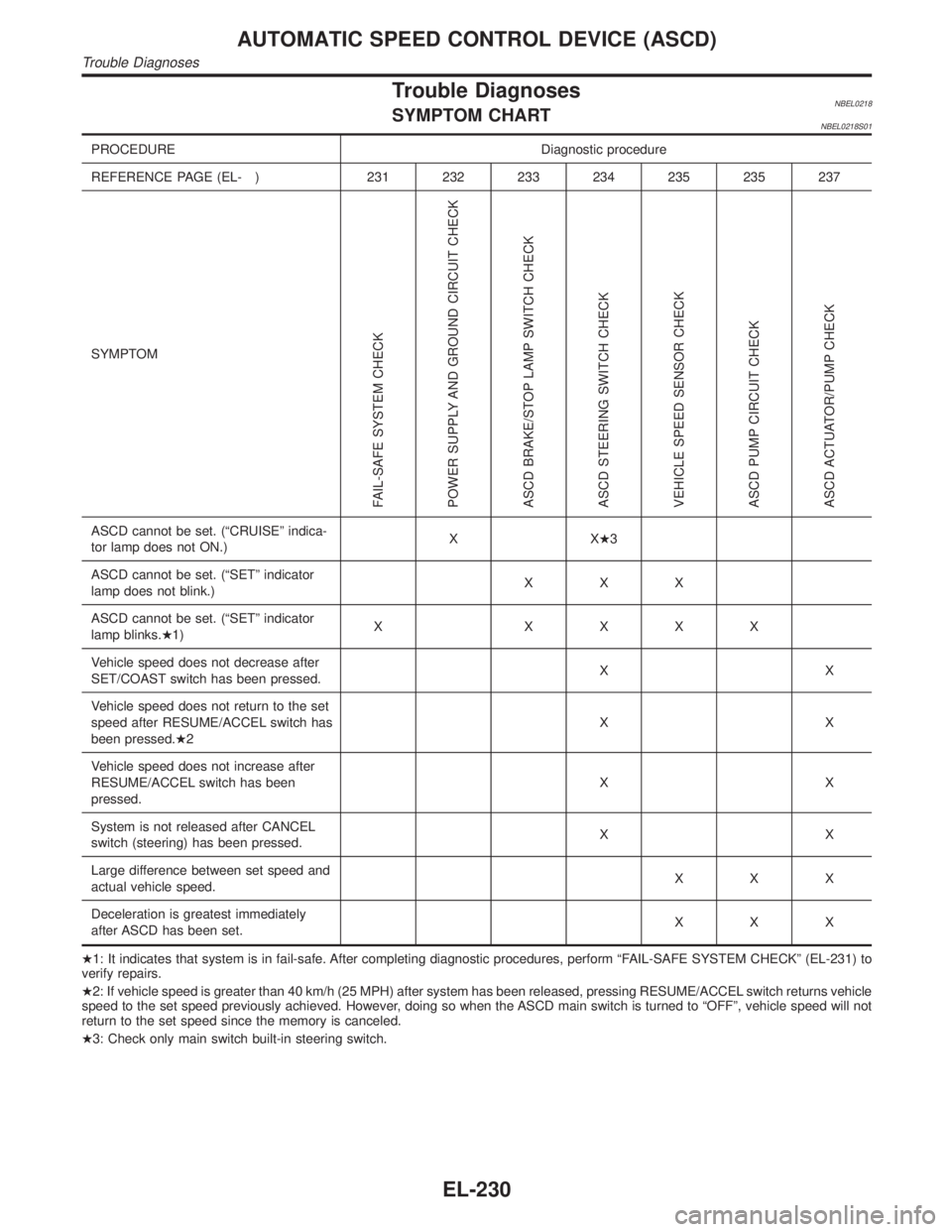
Trouble DiagnosesNBEL0218SYMPTOM CHARTNBEL0218S01
PROCEDURE Diagnostic procedure
REFERENCE PAGE (EL- ) 231 232 233 234 235 235 237
SYMPTOM
FAIL-SAFE SYSTEM CHECK
POWER SUPPLY AND GROUND CIRCUIT CHECK
ASCD BRAKE/STOP LAMP SWITCH CHECK
ASCD STEERING SWITCH CHECK
VEHICLE SPEED SENSOR CHECK
ASCD PUMP CIRCUIT CHECK
ASCD ACTUATOR/PUMP CHECK
ASCD cannot be set. (ªCRUISEº indica-
tor lamp does not ON.)XXH3
ASCD cannot be set. (ªSETº indicator
lamp does not blink.)XXX
ASCD cannot be set. (ªSETº indicator
lamp blinks.H1)X XXXX
Vehicle speed does not decrease after
SET/COAST switch has been pressed.XX
Vehicle speed does not return to the set
speed after RESUME/ACCEL switch has
been pressed.H2XX
Vehicle speed does not increase after
RESUME/ACCEL switch has been
pressed.XX
System is not released after CANCEL
switch (steering) has been pressed.XX
Large difference between set speed and
actual vehicle speed.XXX
Deceleration is greatest immediately
after ASCD has been set.XXX
H1: It indicates that system is in fail-safe. After completing diagnostic procedures, perform ªFAIL-SAFE SYSTEM CHECKº (EL-231) to
verify repairs.
H2: If vehicle speed is greater than 40 km/h (25 MPH) after system has been released, pressing RESUME/ACCEL switch returns vehicle
speed to the set speed previously achieved. However, doing so when the ASCD main switch is turned to ªOFFº, vehicle speed will not
return to the set speed since the memory is canceled.
H3: Check only main switch built-in steering switch.
AUTOMATIC SPEED CONTROL DEVICE (ASCD)
Trouble Diagnoses
EL-230
Page 1421 of 2395
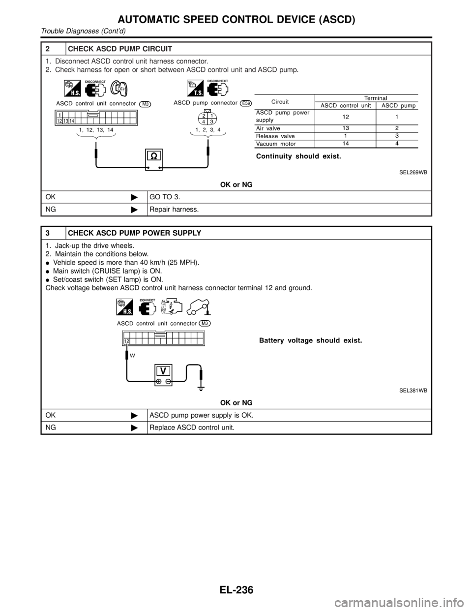
2 CHECK ASCD PUMP CIRCUIT
1. Disconnect ASCD control unit harness connector.
2. Check harness for open or short between ASCD control unit and ASCD pump.
SEL269WB
OK or NG
OK©GO TO 3.
NG©Repair harness.
3 CHECK ASCD PUMP POWER SUPPLY
1. Jack-up the drive wheels.
2. Maintain the conditions below.
IVehicle speed is more than 40 km/h (25 MPH).
IMain switch (CRUISE lamp) is ON.
ISet/coast switch (SET lamp) is ON.
Check voltage between ASCD control unit harness connector terminal 12 and ground.
SEL381WB
OK or NG
OK©ASCD pump power supply is OK.
NG©Replace ASCD control unit.
AUTOMATIC SPEED CONTROL DEVICE (ASCD)
Trouble Diagnoses (Cont'd)
EL-236
Page 1962 of 2395
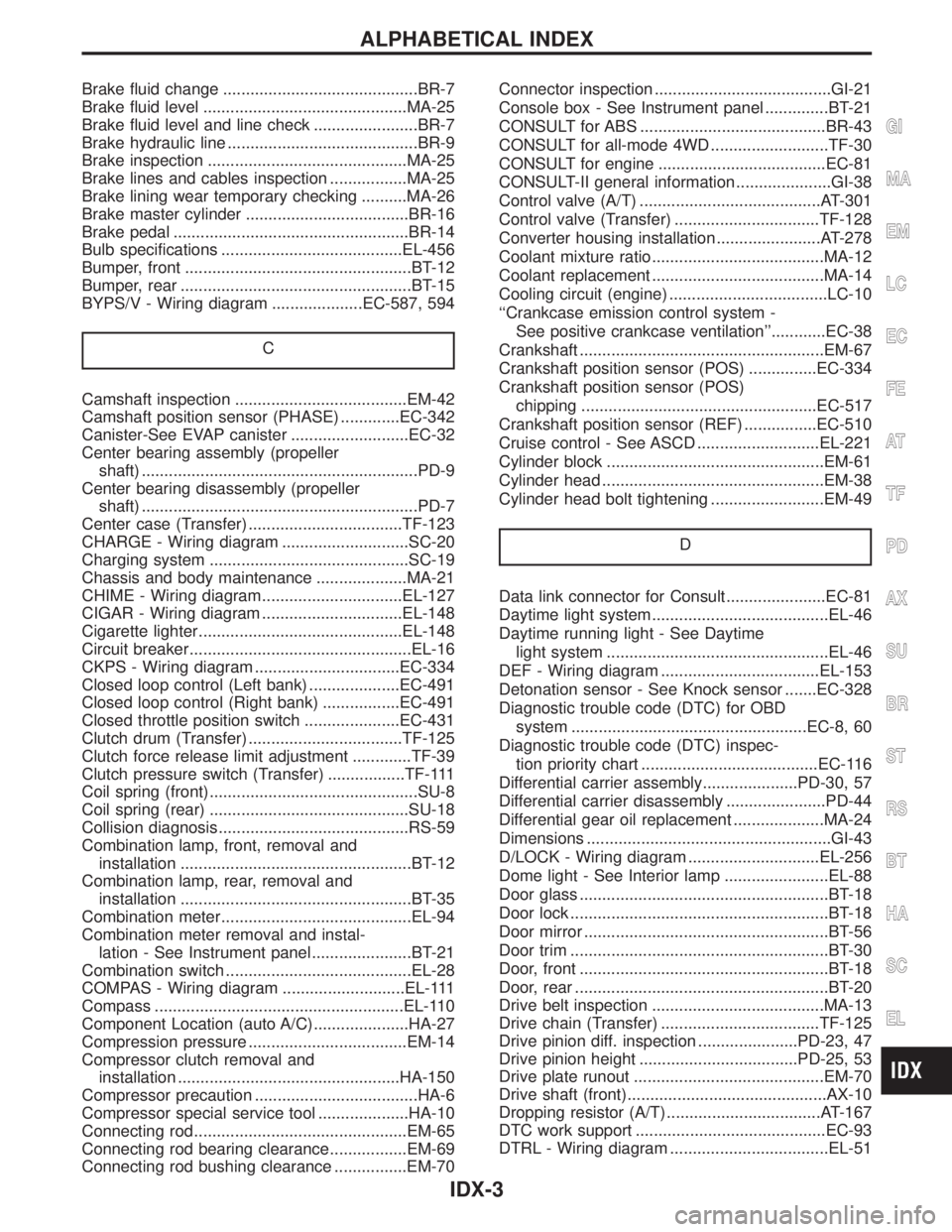
Brake fluid change ...........................................BR-7
Brake fluid level .............................................MA-25
Brake fluid level and line check .......................BR-7
Brake hydraulic line ..........................................BR-9
Brake inspection ............................................MA-25
Brake lines and cables inspection .................MA-25
Brake lining wear temporary checking ..........MA-26
Brake master cylinder ....................................BR-16
Brake pedal ....................................................BR-14
Bulb specifications ........................................EL-456
Bumper, front ..................................................BT-12
Bumper, rear ...................................................BT-15
BYPS/V - Wiring diagram ....................EC-587, 594
C
Camshaft inspection ......................................EM-42
Camshaft position sensor (PHASE) .............EC-342
Canister-See EVAP canister ..........................EC-32
Center bearing assembly (propeller
shaft) .............................................................PD-9
Center bearing disassembly (propeller
shaft) .............................................................PD-7
Center case (Transfer) ..................................TF-123
CHARGE - Wiring diagram ............................SC-20
Charging system ............................................SC-19
Chassis and body maintenance ....................MA-21
CHIME - Wiring diagram...............................EL-127
CIGAR - Wiring diagram ...............................EL-148
Cigarette lighter.............................................EL-148
Circuit breaker.................................................EL-16
CKPS - Wiring diagram ................................EC-334
Closed loop control (Left bank) ....................EC-491
Closed loop control (Right bank) .................EC-491
Closed throttle position switch .....................EC-431
Clutch drum (Transfer) ..................................TF-125
Clutch force release limit adjustment .............TF-39
Clutch pressure switch (Transfer) .................TF-111
Coil spring (front)..............................................SU-8
Coil spring (rear) ............................................SU-18
Collision diagnosis..........................................RS-59
Combination lamp, front, removal and
installation ...................................................BT-12
Combination lamp, rear, removal and
installation ...................................................BT-35
Combination meter..........................................EL-94
Combination meter removal and instal-
lation - See Instrument panel ......................BT-21
Combination switch .........................................EL-28
COMPAS - Wiring diagram ...........................EL-111
Compass .......................................................EL-110
Component Location (auto A/C).....................HA-27
Compression pressure ...................................EM-14
Compressor clutch removal and
installation .................................................HA-150
Compressor precaution ....................................HA-6
Compressor special service tool ....................HA-10
Connecting rod...............................................EM-65
Connecting rod bearing clearance.................EM-69
Connecting rod bushing clearance ................EM-70Connector inspection .......................................GI-21
Console box - See Instrument panel ..............BT-21
CONSULT for ABS .........................................BR-43
CONSULT for all-mode 4WD ..........................TF-30
CONSULT for engine .....................................EC-81
CONSULT-II general information .....................GI-38
Control valve (A/T) ........................................AT-301
Control valve (Transfer) ................................TF-128
Converter housing installation .......................AT-278
Coolant mixture ratio......................................MA-12
Coolant replacement ......................................MA-14
Cooling circuit (engine) ...................................LC-10
``Crankcase emission control system -
See positive crankcase ventilation''............EC-38
Crankshaft ......................................................EM-67
Crankshaft position sensor (POS) ...............EC-334
Crankshaft position sensor (POS)
chipping ....................................................EC-517
Crankshaft position sensor (REF) ................EC-510
Cruise control - See ASCD ...........................EL-221
Cylinder block ................................................EM-61
Cylinder head .................................................EM-38
Cylinder head bolt tightening .........................EM-49
D
Data link connector for Consult......................EC-81
Daytime light system.......................................EL-46
Daytime running light - See Daytime
light system .................................................EL-46
DEF - Wiring diagram ...................................EL-153
Detonation sensor - See Knock sensor .......EC-328
Diagnostic trouble code (DTC) for OBD
system ....................................................EC-8, 60
Diagnostic trouble code (DTC) inspec-
tion priority chart .......................................EC-116
Differential carrier assembly.....................PD-30, 57
Differential carrier disassembly ......................PD-44
Differential gear oil replacement ....................MA-24
Dimensions ......................................................GI-43
D/LOCK - Wiring diagram .............................EL-256
Dome light - See Interior lamp .......................EL-88
Door glass .......................................................BT-18
Door lock .........................................................BT-18
Door mirror ......................................................BT-56
Door trim .........................................................BT-30
Door, front .......................................................BT-18
Door, rear ........................................................BT-20
Drive belt inspection ......................................MA-13
Drive chain (Transfer) ...................................TF-125
Drive pinion diff. inspection ......................PD-23, 47
Drive pinion height ...................................PD-25, 53
Drive plate runout ..........................................EM-70
Drive shaft (front)............................................AX-10
Dropping resistor (A/T) ..................................AT-167
DTC work support ..........................................EC-93
DTRL - Wiring diagram ...................................EL-51
GI
MA
EM
LC
EC
FE
AT
TF
PD
AX
SU
BR
ST
RS
BT
HA
SC
EL
ALPHABETICAL INDEX
IDX-3
Page 2236 of 2395
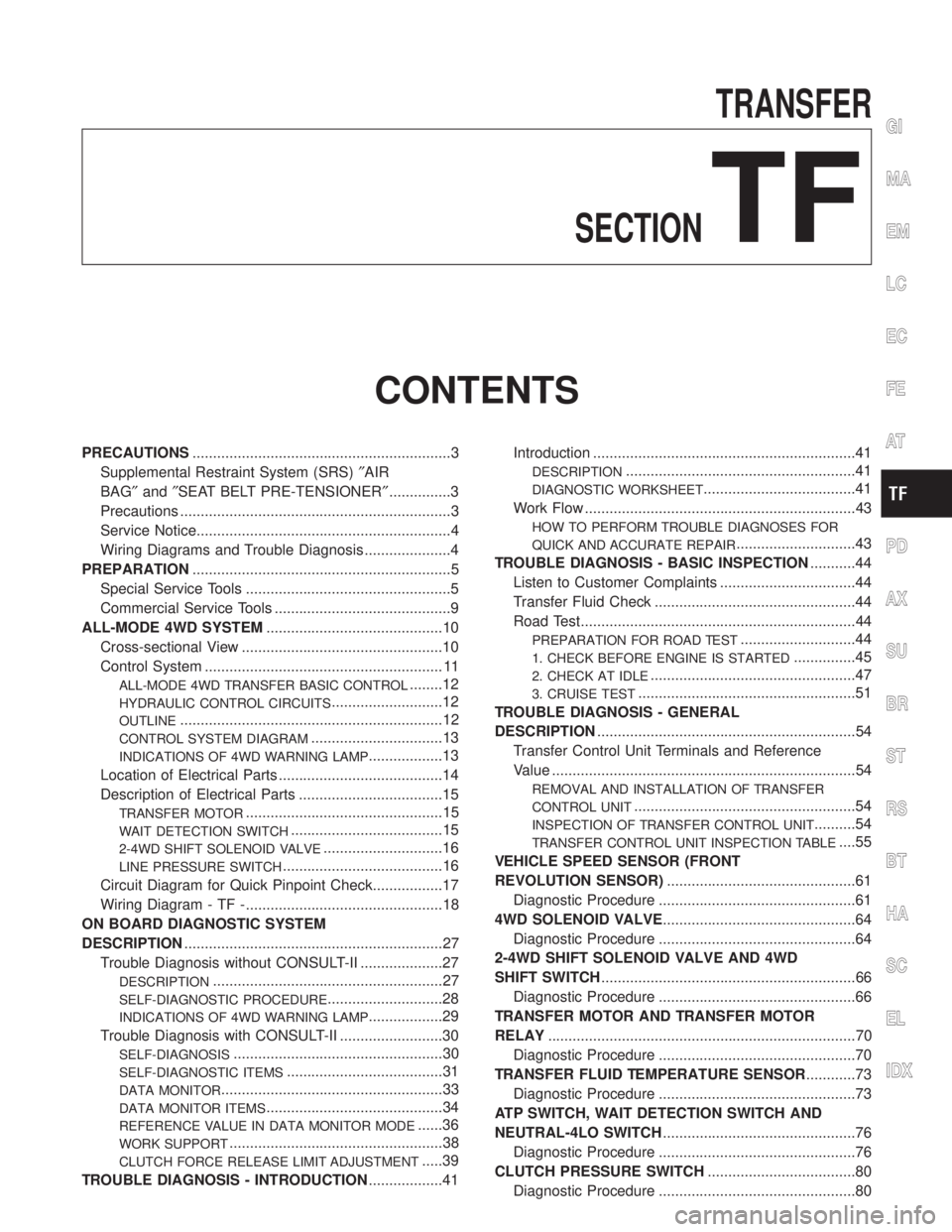
TRANSFER
SECTION
TF
CONTENTS
PRECAUTIONS...............................................................3
Supplemental Restraint System (SRS)²AIR
BAG²and²SEAT BELT PRE-TENSIONER²...............3
Precautions ..................................................................3
Service Notice..............................................................4
Wiring Diagrams and Trouble Diagnosis .....................4
PREPARATION...............................................................5
Special Service Tools ..................................................5
Commercial Service Tools ...........................................9
ALL-MODE 4WD SYSTEM...........................................10
Cross-sectional View .................................................10
Control System .......................................................... 11
ALL-MODE 4WD TRANSFER BASIC CONTROL........12
HYDRAULIC CONTROL CIRCUITS...........................12
OUTLINE................................................................12
CONTROL SYSTEM DIAGRAM................................13
INDICATIONS OF 4WD WARNING LAMP..................13
Location of Electrical Parts ........................................14
Description of Electrical Parts ...................................15
TRANSFER MOTOR................................................15
WAIT DETECTION SWITCH.....................................15
2-4WD SHIFT SOLENOID VALVE.............................16
LINE PRESSURE SWITCH.......................................16
Circuit Diagram for Quick Pinpoint Check.................17
Wiring Diagram - TF -................................................18
ON BOARD DIAGNOSTIC SYSTEM
DESCRIPTION...............................................................27
Trouble Diagnosis without CONSULT-II ....................27
DESCRIPTION........................................................27
SELF-DIAGNOSTIC PROCEDURE............................28
INDICATIONS OF 4WD WARNING LAMP..................29
Trouble Diagnosis with CONSULT-II .........................30
SELF-DIAGNOSIS...................................................30
SELF-DIAGNOSTIC ITEMS......................................31
DATA MONITOR......................................................33
DATA MONITOR ITEMS...........................................34
REFERENCE VALUE IN DATA MONITOR MODE......36
WORK SUPPORT....................................................38
CLUTCH FORCE RELEASE LIMIT ADJUSTMENT.....39
TROUBLE DIAGNOSIS - INTRODUCTION..................41Introduction ................................................................41
DESCRIPTION........................................................41
DIAGNOSTIC WORKSHEET.....................................41
Work Flow ..................................................................43
HOW TO PERFORM TROUBLE DIAGNOSES FOR
QUICK AND ACCURATE REPAIR
.............................43
TROUBLE DIAGNOSIS - BASIC INSPECTION...........44
Listen to Customer Complaints .................................44
Transfer Fluid Check .................................................44
Road Test...................................................................44
PREPARATION FOR ROAD TEST............................44
1. CHECK BEFORE ENGINE IS STARTED...............45
2. CHECK AT IDLE..................................................47
3. CRUISE TEST.....................................................51
TROUBLE DIAGNOSIS - GENERAL
DESCRIPTION...............................................................54
Transfer Control Unit Terminals and Reference
Value ..........................................................................54
REMOVAL AND INSTALLATION OF TRANSFER
CONTROL UNIT
......................................................54
INSPECTION OF TRANSFER CONTROL UNIT..........54
TRANSFER CONTROL UNIT INSPECTION TABLE....55
VEHICLE SPEED SENSOR (FRONT
REVOLUTION SENSOR)..............................................61
Diagnostic Procedure ................................................61
4WD SOLENOID VALVE...............................................64
Diagnostic Procedure ................................................64
2-4WD SHIFT SOLENOID VALVE AND 4WD
SHIFT SWITCH..............................................................66
Diagnostic Procedure ................................................66
TRANSFER MOTOR AND TRANSFER MOTOR
RELAY...........................................................................70
Diagnostic Procedure ................................................70
TRANSFER FLUID TEMPERATURE SENSOR............73
Diagnostic Procedure ................................................73
ATP SWITCH, WAIT DETECTION SWITCH AND
NEUTRAL-4LO SWITCH...............................................76
Diagnostic Procedure ................................................76
CLUTCH PRESSURE SWITCH....................................80
Diagnostic Procedure ................................................80
GI
MA
EM
LC
EC
FE
AT
PD
AX
SU
BR
ST
RS
BT
HA
SC
EL
IDX