2001 INFINITI QX4 headlamp
[x] Cancel search: headlampPage 1186 of 2395

ELECTRICAL SYSTEM
SECTION
EL
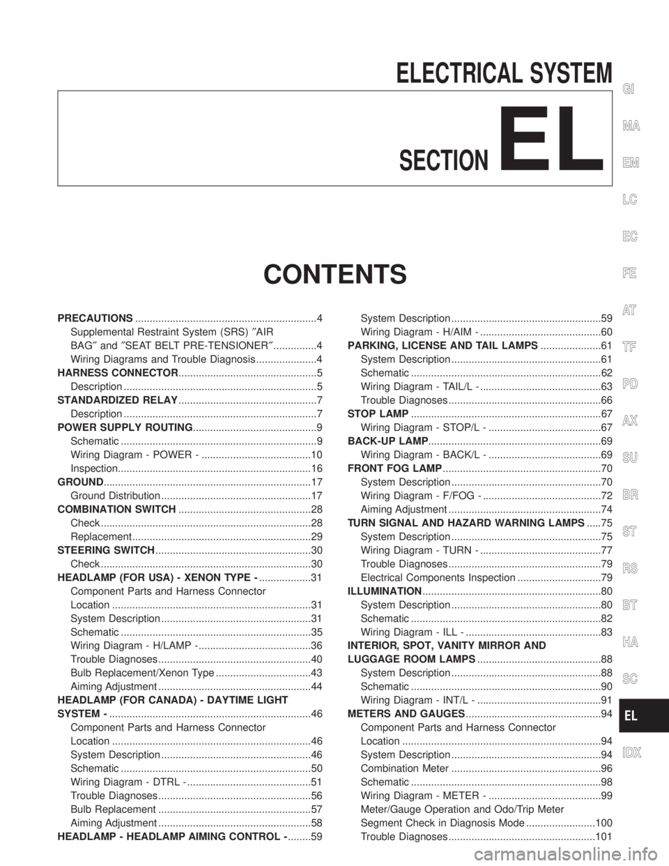
CONTENTS
PRECAUTIONS...............................................................4
Supplemental Restraint System (SRS)²AIR
BAG²and²SEAT BELT PRE-TENSIONER²...............4
Wiring Diagrams and Trouble Diagnosis .....................4
HARNESS CONNECTOR................................................5
Description ...................................................................5
STANDARDIZED RELAY................................................7
Description ...................................................................7
POWER SUPPLY ROUTING...........................................9
Schematic ....................................................................9
Wiring Diagram - POWER - ......................................10
Inspection...................................................................16
GROUND........................................................................17
Ground Distribution ....................................................17
COMBINATION SWITCH..............................................28
Check .........................................................................28
Replacement ..............................................................29
STEERING SWITCH......................................................30
Check .........................................................................30
HEADLAMP (FOR USA) - XENON TYPE -..................31
Component Parts and Harness Connector
Location .....................................................................31
System Description ....................................................31
Schematic ..................................................................35
Wiring Diagram - H/LAMP -.......................................36
Trouble Diagnoses.....................................................40
Bulb Replacement/Xenon Type .................................43
Aiming Adjustment .....................................................44
HEADLAMP (FOR CANADA) - DAYTIME LIGHT
SYSTEM -......................................................................46
Component Parts and Harness Connector
Location .....................................................................46
System Description ....................................................46
Schematic ..................................................................50
Wiring Diagram - DTRL - ...........................................51
Trouble Diagnoses.....................................................56
Bulb Replacement .....................................................57
Aiming Adjustment .....................................................58
HEADLAMP - HEADLAMP AIMING CONTROL -........59System Description ....................................................59
Wiring Diagram - H/AIM - ..........................................60
PARKING, LICENSE AND TAIL LAMPS.....................61
System Description ....................................................61
Schematic ..................................................................62
Wiring Diagram - TAIL/L - ..........................................63
Trouble Diagnoses.....................................................66
STOP LAMP..................................................................67
Wiring Diagram - STOP/L - .......................................67
BACK-UP LAMP............................................................69
Wiring Diagram - BACK/L - .......................................69
FRONT FOG LAMP.......................................................70
System Description ....................................................70
Wiring Diagram - F/FOG - .........................................72
Aiming Adjustment .....................................................74
TURN SIGNAL AND HAZARD WARNING LAMPS.....75
System Description ....................................................75
Wiring Diagram - TURN - ..........................................77
Trouble Diagnoses.....................................................79
Electrical Components Inspection .............................79
ILLUMINATION..............................................................80
System Description ....................................................80
Schematic ..................................................................82
Wiring Diagram - ILL - ...............................................83
INTERIOR, SPOT, VANITY MIRROR AND
LUGGAGE ROOM LAMPS...........................................88
System Description ....................................................88
Schematic ..................................................................90
Wiring Diagram - INT/L - ...........................................91
METERS AND GAUGES...............................................94
Component Parts and Harness Connector
Location .....................................................................94
System Description ....................................................94
Combination Meter ....................................................96
Schematic ..................................................................98
Wiring Diagram - METER - .......................................99
Meter/Gauge Operation and Odo/Trip Meter
Segment Check in Diagnosis Mode ........................100
Trouble Diagnoses...................................................101
GI
MA
EM
LC
EC
FE
AT
TF
PD
AX
SU
BR
ST
RS
BT
HA
SC
IDX
Page 1188 of 2395

Schematic ................................................................255
Wiring Diagram - D/LOCK -.....................................256
Trouble Diagnoses...................................................261
MULTI-REMOTE CONTROL SYSTEM.......................270
Component Parts and Harness Connector
Location ...................................................................270
System Description ..................................................270
Schematic ................................................................273
Wiring Diagram - MULTI - .......................................274
Trouble Diagnoses...................................................277
ID Code Entry Procedure ........................................289
Remote Controller Battery Replacement.................293
THEFT WARNING SYSTEM.......................................294
Component Parts and Harness Connector
Location ...................................................................294
System Description ..................................................295
Schematic ................................................................298
Wiring Diagram - THEFT -.......................................300
Trouble Diagnoses...................................................306
SMART ENTRANCE CONTROL UNIT.......................319
Description ...............................................................319
Schematic ................................................................322
Smart Entrance Control Unit Inspection Table ........324
INTEGRATED HOMELINK TRANSMITTER...............325
Wiring Diagram - TRNSMT - ...................................325
Trouble Diagnoses...................................................326
IVIS (INFINITI VEHICLE IMMOBILIZER SYSTEM -
NATS)...........................................................................328
Component Parts and Harness Connetor
Location ...................................................................328
System Description ..................................................329
System Composition ................................................329
Wiring Diagram - NATS -.........................................330
CONSULT-II .............................................................331
Trouble Diagnoses...................................................334
How to Replace IVIS (NATS) IMMU .......................347
INFINITI COMMUNICATOR (IVCS)............................348
Precaution ................................................................348
Communicator Response Center Telephone
Number for Technicians ...........................................348
Component Parts and Harness Connector
Location ...................................................................349System Description ..................................................350
Schematic ................................................................358
Wiring Diagram - IVCS -..........................................359
CONSULT-II .............................................................363
Trouble Diagnoses...................................................368
Trouble Diagnoses for Intermittent Incident ............377
Demonstration Mode ...............................................379
System Setting (When IVCS Unit is Replaced) ......381
NAVIGATION SYSTEM...............................................385
Component Parts Location ......................................385
System Description ..................................................386
Schematic ................................................................393
Wiring Diagram - NAVI - ..........................................394
Self-diagnosis Mode ................................................397
Confirmation/Adjustment Mode ...............................400
Setting Mode............................................................410
Trouble diagnoses ...................................................417
This Condition is Not Abnormal ...............................423
Program Loading .....................................................432
Initialization ..............................................................433
ELECTRICAL UNITS LOCATION...............................436
Engine Compartment ...............................................436
Passenger Compartment .........................................438
HARNESS LAYOUT....................................................440
How to Read Harness Layout .................................440
Outline......................................................................441
Main Harness...........................................................442
Engine Room Harness ............................................444
Engine Control Harness ..........................................446
Body Harness LH ....................................................448
Body Harness RH ....................................................449
Back Door Harness .................................................450
Engine and Transmission Harness..........................451
Room Lamp Harness...............................................452
Air Bag Harness ......................................................453
Front Door Harness .................................................454
Rear Door Harness..................................................455
BULB SPECIFICATIONS............................................456
Headlamp.................................................................456
Exterior Lamp ..........................................................456
Interior Lamp............................................................456
WIRING DIAGRAM CODES (CELL CODES).............457GI
MA
EM
LC
EC
FE
AT
TF
PD
AX
SU
BR
ST
RS
BT
HA
SC
IDX
CONTENTS(Cont'd)
EL-3
Page 1216 of 2395

Component Parts and Harness Connector
Location
NBEL0159
SEL460X
System DescriptionNBEL0188The headlamp operation is controlled by the lighting switch which is built into the combination switch and
headlamp battery saver control unit. And the headlamp battery saver system is controlled by the headlamp
battery saver control unit and smart entrance control unit.
OUTLINENBEL0188S01Power is supplied at all times
Ito headlamp LH relay terminals 1 and 3
Ithrough 15A fuse (No. 60, located in the fuse and fusible link box), and
Ito headlamp LH relay terminal 6
Ithrough 20A fuse (No. 32, located in the fuse and fusible link box), and
Ito headlamp RH relay terminals 1 and 3
Ithrough 15A fuse (No. 59, located in the fuse and fusible link box), and
Ito headlamp RH relay terminal 6
Ithrough 20A fuse (No. 31, located in the fuse and fusible link box), and
Ito headlamp battery saver control unit terminal 7, and
Ito smart entrance control unit terminal 10
Ithrough 7.5A fuse [No. 24, located in the fuse block (J/B)].
When the ignition switch is in the ON or START position, power is supplied
Ito headlamp battery saver control unit terminal 1
Ithrough 10A fuse [No. 16, located in the fuse block (J/B)], and
Ito headlamp battery saver control unit terminal 10,
Ito auto light control unit terminal 1 and
Ito smart entrance control unit terminal 33
Ithrough 7.5A fuse [No. 11, located in the fuse block (J/B)].
GI
MA
EM
LC
EC
FE
AT
TF
PD
AX
SU
BR
ST
RS
BT
HA
SC
IDX
HEADLAMP (FOR USA) Ð XENON TYPE Ð
Component Parts and Harness Connector Location
EL-31
Page 1217 of 2395
![INFINITI QX4 2001 Factory Service Manual When the ignition switch is in the ACC or ON position, power is supplied
Ito auto light control unit terminal 2
Ithrough 10A fuse [No. 9, located in the fuse block (J/B)]
Ground is supplied
Ito headla INFINITI QX4 2001 Factory Service Manual When the ignition switch is in the ACC or ON position, power is supplied
Ito auto light control unit terminal 2
Ithrough 10A fuse [No. 9, located in the fuse block (J/B)]
Ground is supplied
Ito headla](/manual-img/42/57027/w960_57027-1216.png)
When the ignition switch is in the ACC or ON position, power is supplied
Ito auto light control unit terminal 2
Ithrough 10A fuse [No. 9, located in the fuse block (J/B)]
Ground is supplied
Ito headlamp battery saver control unit terminals 4 and 11
Ithrough body grounds M77 and M111, and M4,M66 and M147
Ito auto light control unit terminal 5
Ithrough body grounds M4, M66 and M147.
Power Supply to Low Beam and High BeamNBEL0188S0101When lighting switch is in 2ND or PASS position, ground is supplied
Ito headlamp relay (LH and RH) terminal 2 from headlamp battery saver control unit terminals 2 and 8
Ithrough headlamp battery saver control unit terminals 3 and 9,
Ifrom lighting switch terminal 12.
Headlamp relays (LH and RH) are energized and then power is supplied to headlamps (LH and RH).
LOW BEAM OPERATIONNBEL0188S02When the lighting switch is turned to the 2ND position and placed in LOW (ªBº) position, power is supplied
Ifrom terminal 7 of each headlamp relay
Ito terminal 3 of each headlamp
Ground is supplied
Ito terminal 4 of each headlamp
Ithrough body grounds E13 and E41.
With power and ground supplied, the headlamp(s) will illuminate.
HIGH BEAM OPERATION/FLASH-TO-PASS OPERATIONNBEL0188S03When the lighting switch is turned to the 2ND position and placed in HIGH (ªAº) position or PASS (ªCº) position,
power is supplied
Ifrom terminal 5 of headlamp LH relay
Ito terminal 1 of headlamp LH, and
Ito combination meter terminal 26 for the HIGH BEAM indicator
Ifrom terminal 5 of headlamp RH relay
Ito terminal 1 of headlamp RH.
Ground is supplied
Ito headlamp LH terminal 2
Ito combination meter terminal 27 for the HIGH BEAM indicator
Ithrough lighting switch terminals 6 and 5
Ithrough body grounds E13 and E41, and
Ito headlamp RH terminal 2
Ithrough lighting switch terminals 9 and 8
Ithrough body grounds E13 and E41.
With power and ground supplied, the high beams and the high beam indicator illuminate.
BATTERY SAVER CONTROLNBEL0188S04When the ignition switch is turned from ON (or START) to OFF (or ACC) positions while headlamps illuminate,
the RAP signal is supplied to terminal 10 of the headlamp battery saver control unit from smart entrance con-
trol unit terminal 5.
After counting 45 seconds by the RAP signal from the smart entrance control unit to headlamp battery saver
control unit, the ground supply to terminal 2 of the headlamp LH and RH relay from headlamp battery saver
control unit terminals 2 and 8 is terminated.
Then the headlamps are turned off.
The headlamps are turned off when driver or passenger side door is opened even if 45 seconds have not
passed after ignition switch is turned from ON (or START) to OFF (or ACC) positions while headlamps are
illuminated.
When the lighting switch is turned from OFF to 2ND after headlamps are turned to off by the battery saver
control, ground is supplied
HEADLAMP (FOR USA) Ð XENON TYPE Ð
System Description (Cont'd)
EL-32
Page 1218 of 2395

Ito headlamp battery saver control unit terminals 5 and 13 from lighting switch terminal 11, and
Ito headlamp LH and RH relays terminal 2 from headlamp battery saver control unit terminals 2 and 8
Ithrough headlamp battery saver control unit terminals 3 and 9, and
Ithrough lighting switch terminal 12.
Then headlamps illuminate again.
AUTO LIGHT OPERATIONNBEL0188S05When lighting switch is in ªAUTOº position, ground is supplied
Ito auto light control unit terminal 10
Ifrom lighting switch terminal 42.
When ignition switch is turn to ªONº or ªSTARTº position and outside brightness is darker than prescribed level.
Ground is supplied
Ito headlamp relay LH and RH terminals 2
Ithrough battery saver control unit
Ifrom auto light control unit terminal 6, and
Ito tail lamp relay terminal 1
Ithrough battery saver control unit
Ifrom auto light control unit terminal 7.
Then both headlamp relays and tail lamp relay are energized, headlamps (low or high) and tail lamps are illu-
minate according to switch position.
Auto light operation allows headlamps and tail lamps to go off when
IIgnition switch is turned to ªOFFº position or
IOutside brightness is brighter than prescribed level.
NOTE:
The delay time is varies up to maximum of 20 seconds as the outside brightness changes.
For parking, license and tail lamp auto operation, refer to ªPARKING, LICENSE AND TAIL LAMPSº.
THEFT WARNING SYSTEMNBEL0188S06The theft warning system will flash the low beams if the system is triggered. Refer to ªTHEFT WARNING
SYSTEMº (EL-296).
GI
MA
EM
LC
EC
FE
AT
TF
PD
AX
SU
BR
ST
RS
BT
HA
SC
IDX
HEADLAMP (FOR USA) Ð XENON TYPE Ð
System Description (Cont'd)
EL-33
Page 1219 of 2395

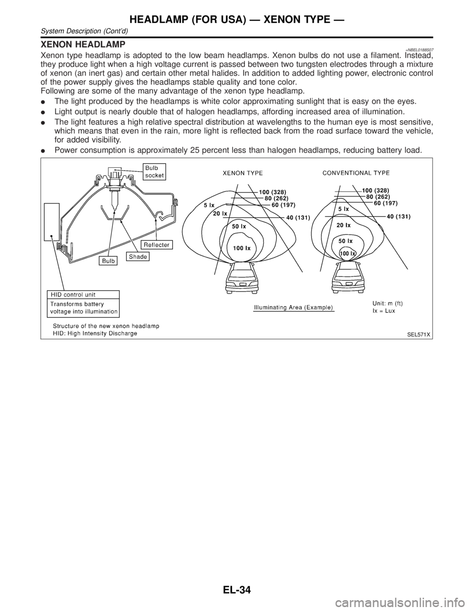
XENON HEADLAMP=NBEL0188S07Xenon type headlamp is adopted to the low beam headlamps. Xenon bulbs do not use a filament. Instead,
they produce light when a high voltage current is passed between two tungsten electrodes through a mixture
of xenon (an inert gas) and certain other metal halides. In addition to added lighting power, electronic control
of the power supply gives the headlamps stable quality and tone color.
Following are some of the many advantage of the xenon type headlamp.
IThe light produced by the headlamps is white color approximating sunlight that is easy on the eyes.
ILight output is nearly double that of halogen headlamps, affording increased area of illumination.
IThe light features a high relative spectral distribution at wavelengths to the human eye is most sensitive,
which means that even in the rain, more light is reflected back from the road surface toward the vehicle,
for added visibility.
IPower consumption is approximately 25 percent less than halogen headlamps, reducing battery load.
SEL571X
HEADLAMP (FOR USA) Ð XENON TYPE Ð
System Description (Cont'd)
EL-34
Page 1220 of 2395

SchematicNBEL0160
MEL761L
GI
MA
EM
LC
EC
FE
AT
TF
PD
AX
SU
BR
ST
RS
BT
HA
SC
IDX
HEADLAMP (FOR USA) Ð XENON TYPE Ð
Schematic
EL-35
Page 1221 of 2395

Wiring Diagram Ð H/LAMP ÐNBEL0013
MEL001O
HEADLAMP (FOR USA) Ð XENON TYPE Ð
Wiring Diagram Ð H/LAMP Ð
EL-36