2001 INFINITI QX4 check transmission fluid
[x] Cancel search: check transmission fluidPage 359 of 2395

SAT010B
j. Install torque converter clutch solenoid valve and A/T fluid tem-
perature sensor connectors.
SAT011B
11. Install oil pan.
a. Attach a magnet to oil pan.
SAT365I
b. Install new oil pan gasket on transmission case.
c. Install oil pan and bracket on transmission case.
IAlways replace oil pan bolts as they are self-sealing bolts.
IBefore installing bolts, remove traces of sealant and oil
from mating surface and thread holes.
ITighten four bolts in a criss-cross pattern to prevent dis-
location of gasket.
d. Tighten drain plug.
SAT299I
12. Install PNP switch.
a. Check that manual shaft is in ª1º position.
b. Temporarily install PNP switch on manual shaft.
c. Move manual shaft to ªNº.
SAT014B
d. Tighten bolts while inserting 4.0 mm (0.157 in) dia. pin verti-
cally into locating holes in PNP switch and manual shaft.
ASSEMBLY
Assembly (2) (Cont'd)
AT-354
Page 592 of 2395

SEF452Y
Idle Air Volume LearningNBEC0642
SEF454Y
SEF455Y
DESCRIPTIONNBEC0642S01ªIdle Air Volume Learningº is an operation to learn the idle air vol-
ume that keeps each engine within the specific range. It must be
performed under any of the following conditions:
IEach time IACV-AAC valve, throttle body or ECM is replaced.
IIdle speed or ignition timing is out of specification.
PRE-CONDITIONINGNBEC0642S02Before performing ªIdle Air Volume Learningº, make sure that all of
the following conditions are satisfied.
Learning will be cancelled if any of the following conditions are
missed for even a moment.
IBattery voltage: More than 12.9V (At idle)
IEngine coolant temperature: 70 - 99ÉC (158 - 210ÉF)
IPNP switch: ON
IElectric load switch: OFF
(Air conditioner, headlamp, rear window defogger)
On vehicles equipped with daytime running light systems, if
the parking brake is applied before the engine is started the
headlamp will not illuminate.
ICooling fan motor: Not operating
ISteering wheel: Neutral (Straight-ahead position)
IVehicle speed: Stopped
ITransmission: Warmed-up
For A/T models with CONSULT-II, drive vehicle until ªFLUID
TEMP SEº in ªDATA MONITORº mode of ªA/Tº system indi-
cates less than 0.9V.
For A/T models without CONSULT-II, drive vehicle for 10 min-
utes.
OPERATION PROCEDURENBEC0642S03With CONSULT-IINBEC0642S03011. Turn ignition switch ªONº and wait at least 1 second.
2. Turn ignition switch ªOFFº and wait at least 10 seconds.
3. Start engine and warm it up to normal operating temperature.
4. Check that all items listed under the topic ªPRE-CONDITION-
INGº (previously mentioned) are in good order.
5. Turn ignition switch ªOFFº and wait at least 10 seconds.
6. Start the engine and let it idle for at least 30 seconds.
7. Select ªIDLE AIR VOL LEARNº in ªWORK SUPPORTº mode.
8. Touch ªSTARTº and wait 20 seconds.
9. Make sure that ªCMPLTº is displayed on CONSULT-II screen.
If ªINCMPº is displayed, ªIdle Air Volume Learningº will not be
carried out successfully. In this case, find the cause of the
problem by referring to the NOTE below.
10. Rev up the engine two or three times. Make sure that idle
speed and ignition timing are within specifications.
ITEM SPECIFICATION
Idle speed 750±50 rpm (in ªPº or ªNº position)
Ignition timing 15ɱ5É BTDC (in ªPº or ªNº position)
GI
MA
EM
LC
FE
AT
TF
PD
AX
SU
BR
ST
RS
BT
HA
SC
EL
IDX
BASIC SERVICE PROCEDURE
Idle Air Volume Learning
EC-57
Page 965 of 2395

10 CHECK IACV-AAC VALVE-II
1. Reconnect IACV-AAC valve harness connector and ECM harness connector.
2. Turn ignition switch ªONº and ªOFFº, and ensure the IACV-AAC valve makes operating sound according to the ignition
switch position.
SEF997Y
OK or NG
OK©GO TO 12.
NG©GO TO 11.
11 REPLACE IACV-AAC VALVE
1. Replace IACV-AAC valve assembly.
2. Perform ªIdle Air Volume Learningº, EC-57.
Is the result CMPLT or INCMP?
CMPLT or INCMP
CMPLT©INSPECTION END
INCMP©Follow the construction of ªIdle Air Volume Learningº.
12 CHECK TARGET IDLE SPEED
1. Turn ignition switch ªOFFº.
2. Reconnect all harness connectors and vacuum hoses.
3. Start engine and warm it up to normal operating temperature.
4. Also warm up transmission to normal operating temperature.
IFor A/T models with CONSULT-II, drive vehicle until ªFLUID TEMP SEº in ªDATA MONITORº mode of ªA/Tº system indi-
cates less than 0.9V.
IFor A/T models without CONSULT-II, drive vehicle for 10 minutes.
5. Stop vehicle with engine running.
6. Check target idle speed.
A/T: 750±50 rpm (in ªPº or ªNº position)
OK or NG
OK©GO TO 13.
NG©Perform ªIdle Air Volume Learningº, EC-57.
13 CHECK INTERMITTENT INCIDENT
Refer to ªTROUBLE DIAGNOSIS FOR INTERMITTENT INCIDENTº, EC-140.
©INSPECTION END
DTC P0505 IDLE AIR CONTROL VALVE (IACV) Ð AUXILIARY AIR CONTROL
(AAC) VALVE
Diagnostic Procedure (Cont'd)
EC-430
Page 1751 of 2395
IClean all disassembled parts in the designated liquid or solvent
prior to inspection or assembly.
IReplace oil seals, gaskets, packings, O-rings, locking washers,
cotter pins, self-locking nuts, etc. with new ones.
IReplace inner and outer races of tapered roller bearings and
needle bearings as a set.
IArrange the disassembled parts in accordance with their
assembled locations and sequence.
IDo not touch the terminals of electrical components which use
microcomputers (such as ECMs).
Static electricity may damage internal electronic components.
IAfter disconnecting vacuum or air hoses, attach a tag to indi-
cate the proper connection.
IUse only the fluids and lubricants specified in this manual.
IUse approved bonding agent, sealants or their equivalents
when required.
IUse tools and recommended special tools where specified for
safe and efficient service repairs.
IWhen repairing the fuel, oil, water, vacuum or exhaust
systems, check all affected lines for leaks.
IDispose of drained oil or the solvent used for cleaning parts in
an appropriate manner.
WARNING:
To prevent ECM from storing the diagnostic trouble codes, do
not carelessly disconnect the harness connectors which are
related to the engine control system and TCM (Transmission
Control Module) system. The connectors should be discon-
nected only when working according to the WORK FLOW of
TROUBLE DIAGNOSES in EC and AT sections.
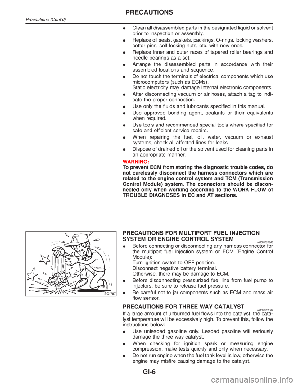
SGI787
PRECAUTIONS FOR MULTIPORT FUEL INJECTION
SYSTEM OR ENGINE CONTROL SYSTEM
NBGI0001S03IBefore connecting or disconnecting any harness connector for
the multiport fuel injection system or ECM (Engine Control
Module):
Turn ignition switch to OFF position.
Disconnect negative battery terminal.
Otherwise, there may be damage to ECM.
IBefore disconnecting pressurized fuel line from fuel pump to
injectors, be sure to release fuel pressure.
IBe careful not to jar components such as ECM and mass air
flow sensor.
PRECAUTIONS FOR THREE WAY CATALYSTNBGI0001S04If a large amount of unburned fuel flows into the catalyst, the cata-
lyst temperature will be excessively high. To prevent this, follow the
instructions below:
IUse unleaded gasoline only. Leaded gasoline will seriously
damage the three way catalyst.
IWhen checking for ignition spark or measuring engine
compression, make tests quickly and only when necessary.
IDo not run engine when the fuel tank level is low, otherwise the
engine may misfire causing damage to the catalyst.
PRECAUTIONS
Precautions (Cont'd)
GI-6
Page 1755 of 2395
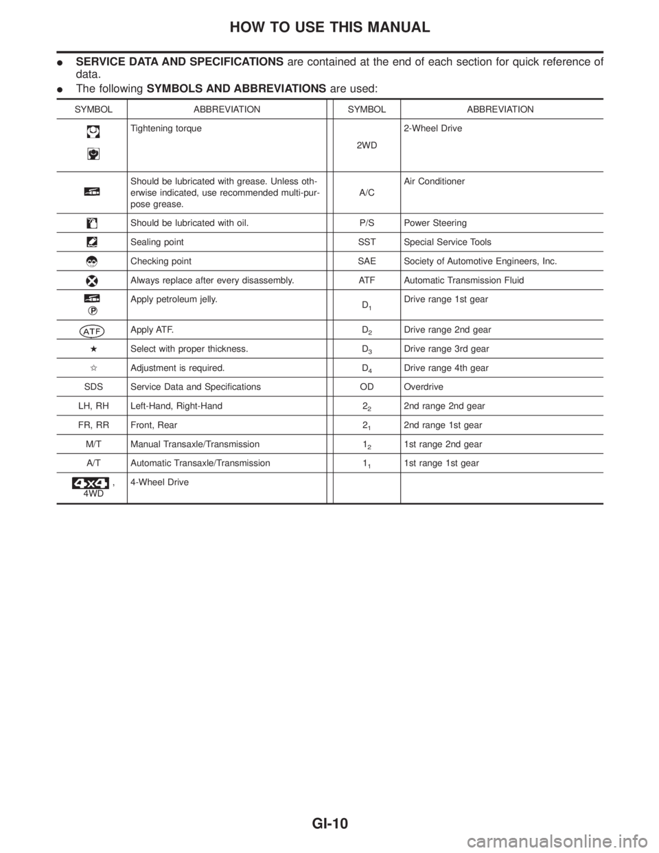
ISERVICE DATA AND SPECIFICATIONSare contained at the end of each section for quick reference of
data.
IThe followingSYMBOLS AND ABBREVIATIONSare used:
SYMBOL ABBREVIATION SYMBOL ABBREVIATION
Tightening torque
2WD2-Wheel Drive
Should be lubricated with grease. Unless oth-
erwise indicated, use recommended multi-pur-
pose grease.A/CAir Conditioner
Should be lubricated with oil. P/S Power Steering
Sealing point SST Special Service Tools
Checking point SAE Society of Automotive Engineers, Inc.
Always replace after every disassembly. ATF Automatic Transmission Fluid
qP
Apply petroleum jelly.
D1Drive range 1st gear
Apply ATF. D2Drive range 2nd gear
HSelect with proper thickness. D
3Drive range 3rd gear
IAdjustment is required. D
4Drive range 4th gear
SDS Service Data and Specifications OD Overdrive
LH, RH Left-Hand, Right-Hand 2
22nd range 2nd gear
FR, RR Front, Rear 2
12nd range 1st gear
M/T Manual Transaxle/Transmission 1
21st range 2nd gear
A/T Automatic Transaxle/Transmission 1
11st range 1st gear
,
4WD4-Wheel Drive
HOW TO USE THIS MANUAL
GI-10
Page 1961 of 2395
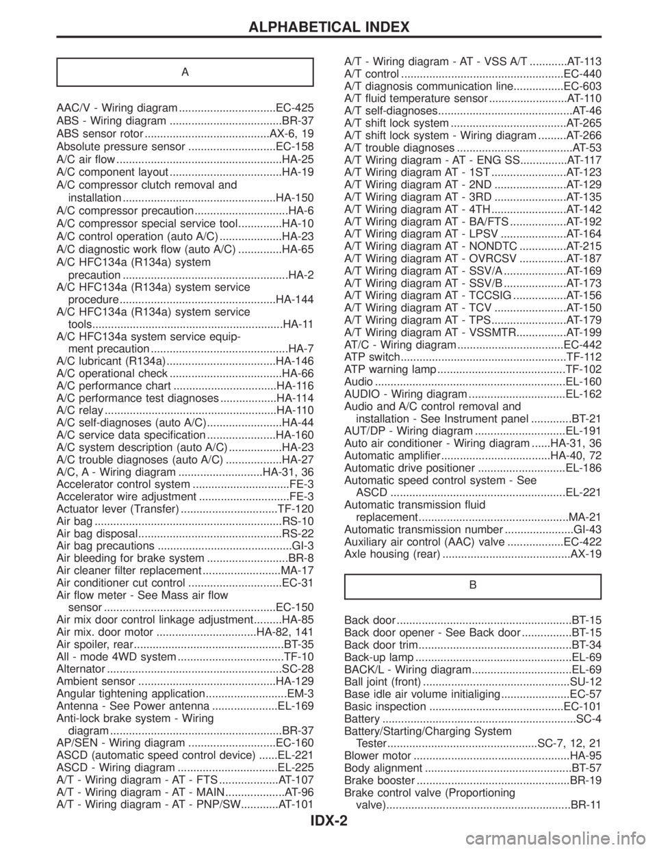
A
AAC/V - Wiring diagram ...............................EC-425
ABS - Wiring diagram ....................................BR-37
ABS sensor rotor ........................................AX-6, 19
Absolute pressure sensor ............................EC-158
A/C air flow .....................................................HA-25
A/C component layout ....................................HA-19
A/C compressor clutch removal and
installation .................................................HA-150
A/C compressor precaution..............................HA-6
A/C compressor special service tool..............HA-10
A/C control operation (auto A/C) ....................HA-23
A/C diagnostic work flow (auto A/C) ..............HA-65
A/C HFC134a (R134a) system
precaution .....................................................HA-2
A/C HFC134a (R134a) system service
procedure ..................................................HA-144
A/C HFC134a (R134a) system service
tools.............................................................HA-11
A/C HFC134a system service equip-
ment precaution ............................................HA-7
A/C lubricant (R134a)...................................HA-146
A/C operational check ....................................HA-66
A/C performance chart .................................HA-116
A/C performance test diagnoses ..................HA-114
A/C relay .......................................................HA-110
A/C self-diagnoses (auto A/C)........................HA-44
A/C service data specification ......................HA-160
A/C system description (auto A/C) .................HA-23
A/C trouble diagnoses (auto A/C) ..................HA-27
A/C, A - Wiring diagram ...........................HA-31, 36
Accelerator control system ...............................FE-3
Accelerator wire adjustment .............................FE-3
Actuator lever (Transfer) ...............................TF-120
Air bag ............................................................RS-10
Air bag disposal..............................................RS-22
Air bag precautions ...........................................GI-3
Air bleeding for brake system ..........................BR-8
Air cleaner filter replacement .........................MA-17
Air conditioner cut control ..............................EC-31
Air flow meter - See Mass air flow
sensor .......................................................EC-150
Air mix door control linkage adjustment.........HA-85
Air mix. door motor ................................HA-82, 141
Air spoiler, rear................................................BT-35
All - mode 4WD system ..................................TF-10
Alternator ........................................................SC-28
Ambient sensor ............................................HA-129
Angular tightening application..........................EM-3
Antenna - See Power antenna .....................EL-169
Anti-lock brake system - Wiring
diagram .......................................................BR-37
AP/SEN - Wiring diagram ............................EC-160
ASCD (automatic speed control device) ......EL-221
ASCD - Wiring diagram ................................EL-225
A/T - Wiring diagram - AT - FTS ...................AT-107
A/T - Wiring diagram - AT - MAIN ...................AT-96
A/T - Wiring diagram - AT - PNP/SW............AT-101A/T - Wiring diagram - AT - VSS A/T ............AT-113
A/T control ....................................................EC-440
A/T diagnosis communication line................EC-603
A/T fluid temperature sensor .........................AT-110
A/T self-diagnoses...........................................AT-46
A/T shift lock system .....................................AT-265
A/T shift lock system - Wiring diagram .........AT-266
A/T trouble diagnoses .....................................AT-53
A/T Wiring diagram - AT - ENG SS...............AT-117
A/T Wiring diagram AT - 1ST ........................AT-123
A/T Wiring diagram AT - 2ND .......................AT-129
A/T Wiring diagram AT - 3RD .......................AT-135
A/T Wiring diagram AT - 4TH ........................AT-142
A/T Wiring diagram AT - BA/FTS ..................AT-192
A/T Wiring diagram AT - LPSV .....................AT-164
A/T Wiring diagram AT - NONDTC ...............AT-215
A/T Wiring diagram AT - OVRCSV ...............AT-187
A/T Wiring diagram AT - SSV/A ....................AT-169
A/T Wiring diagram AT - SSV/B ....................AT-173
A/T Wiring diagram AT - TCCSIG .................AT-156
A/T Wiring diagram AT - TCV .......................AT-150
A/T Wiring diagram AT - TPS........................AT-179
A/T Wiring diagram AT - VSSMTR................AT-199
AT/C - Wiring diagram ..................................EC-442
ATP switch.....................................................TF-112
ATP warning lamp .........................................TF-102
Audio .............................................................EL-160
AUDIO - Wiring diagram ...............................EL-162
Audio and A/C control removal and
installation - See Instrument panel .............BT-21
AUT/DP - Wiring diagram .............................EL-191
Auto air conditioner - Wiring diagram ......HA-31, 36
Automatic amplifier...................................HA-40, 72
Automatic drive positioner ............................EL-186
Automatic speed control system - See
ASCD ........................................................EL-221
Automatic transmission fluid
replacement ................................................MA-21
Automatic transmission number ......................GI-43
Auxiliary air control (AAC) valve ..................EC-422
Axle housing (rear) .........................................AX-19
B
Back door ........................................................BT-15
Back door opener - See Back door ................BT-15
Back door trim.................................................BT-34
Back-up lamp ..................................................EL-69
BACK/L - Wiring diagram................................EL-69
Ball joint (front) ...............................................SU-12
Base idle air volume initialiging......................EC-57
Basic inspection ...........................................EC-101
Battery ..............................................................SC-4
Battery/Starting/Charging System
Tester ................................................SC-7, 12, 21
Blower motor ..................................................HA-95
Body alignment ...............................................BT-57
Brake booster .................................................BR-19
Brake control valve (Proportioning
valve)...........................................................BR-11
ALPHABETICAL INDEX
IDX-2
Page 2003 of 2395
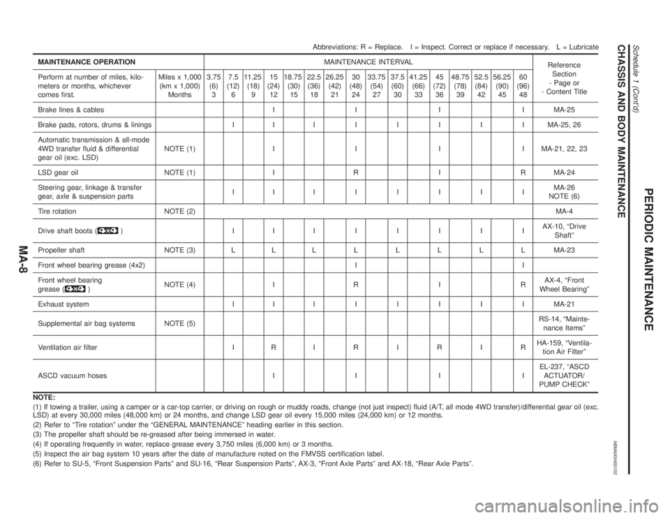
CHASSIS AND BODY MAINTENANCENBMA0004S0102
Abbreviations: R = Replace. I = Inspect. Correct or replace if necessary. L = Lubricate
MAINTENANCE OPERATIONMAINTENANCE INTERVAL
Reference
Section
- Page or
- Content Title Perform at number of miles, kilo-
meters or months, whichever
comes first.Miles x 1,000
(km x 1,000)
Months3.75
(6)
37.5
(12)
611.25
(18)
915
(24)
1218.75
(30)
1522.5
(36)
1826.25
(42)
2130
(48)
2433.75
(54)
2737.5
(60)
3041.25
(66)
3345
(72)
3648.75
(78)
3952.5
(84)
4256.25
(90)
4560
(96)
48
Brake lines & cables I I I I MA-25
Brake pads, rotors, drums & linings I IIIIIIIMA-25, 26
Automatic transmission & all-mode
4WD transfer fluid & differential
gear oil (exc. LSD)NOTE (1) I I I I MA-21, 22, 23
LSD gear oil NOTE (1) I R I R MA-24
Steering gear, linkage & transfer
gear, axle & suspension partsIIIIIIIIMA-26
NOTE (6)
Tire rotation NOTE (2)MA-4
Drive shaft boots (
) IIIIIIIIAX-10, ªDrive
Shaftº
Propeller shaft NOTE (3) L LLLLLLLMA-23
Front wheel bearing grease (4x2) I I
Front wheel bearing
grease (
)NOTE (4) I R I RAX-4, ªFront
Wheel Bearingº
Exhaust system I IIIIIIIMA-21
Supplemental air bag systems NOTE (5)RS-14, ªMainte-
nance Itemsº
Ventilation air filter I RIRIRIRHA-159, ªVentila-
tion Air Filterº
ASCD vacuum hoses I I I IEL-237, ªASCD
ACTUATOR/
PUMP CHECKº
NOTE:
(1) If towing a trailer, using a camper or a car-top carrier, or driving on rough or muddy roads, change (not just inspect) fluid (A/T, all mode 4WD transfer)/differential gear oil (exc.
LSD) at every 30,000 miles (48,000 km) or 24 months, and change LSD gear oil every 15,000 miles (24,000 km) or 12 months.
(2) Refer to ªTire rotationº under the ªGENERAL MAINTENANCEº heading earlier in this section.
(3) The propeller shaft should be re-greased after being immersed in water.
(4) If operating frequently in water, replace grease every 3,750 miles (6,000 km) or 3 months.
(5) Inspect the air bag system 10 years after the date of manufacture noted on the FMVSS certification label.
(6) Refer to SU-5, ªFront Suspension Partsº and SU-16, ªRear Suspension Partsº, AX-3, ªFront Axle Partsº and AX-18, ªRear Axle Partsº.
PERIODIC MAINTENANCE
Schedule 1 (Cont'd)
MA-8
Page 2005 of 2395
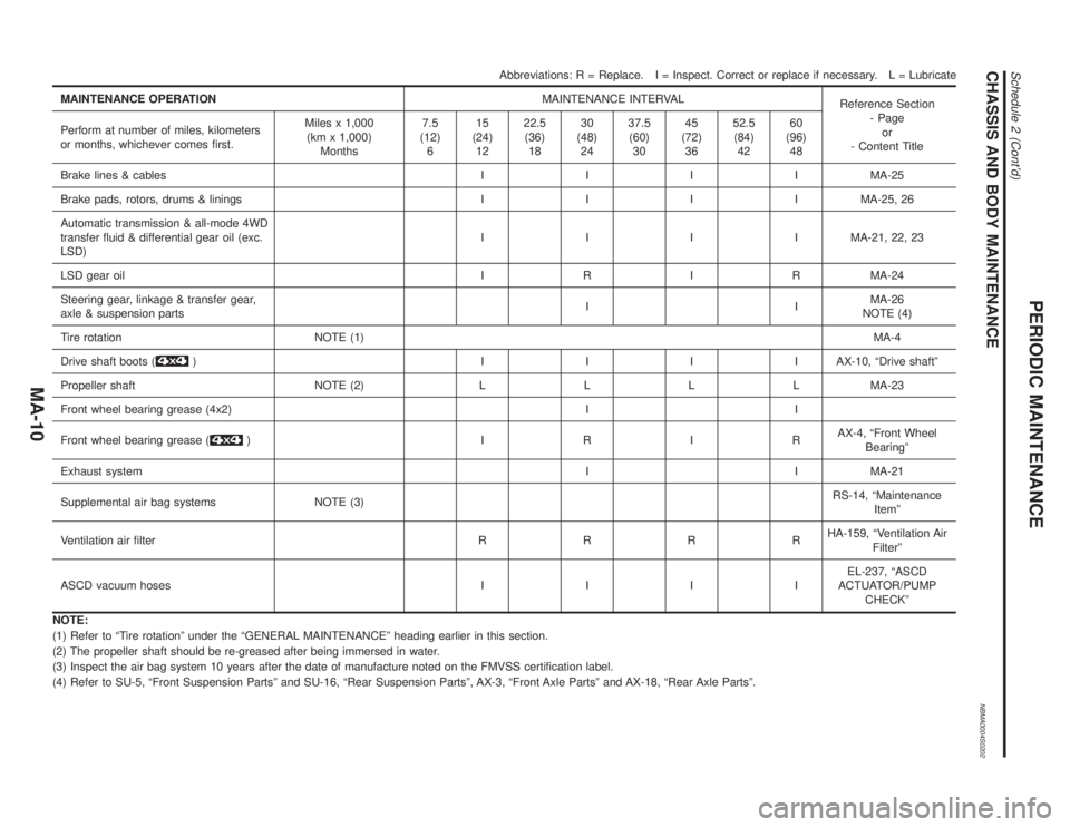
CHASSIS AND BODY MAINTENANCENBMA0004S0202
Abbreviations: R = Replace. I = Inspect. Correct or replace if necessary. L = Lubricate
MAINTENANCE OPERATIONMAINTENANCE INTERVAL
Reference Section
- Page
or
- Content Title Perform at number of miles, kilometers
or months, whichever comes first.Miles x 1,000
(km x 1,000)
Months7.5
(12)
615
(24)
1222.5
(36)
1830
(48)
2437.5
(60)
3045
(72)
3652.5
(84)
4260
(96)
48
Brake lines & cablesIIIIMA-25
Brake pads, rotors, drums & liningsIIIIMA-25, 26
Automatic transmission & all-mode 4WD
transfer fluid & differential gear oil (exc.
LSD)IIIIMA-21, 22, 23
LSD gear oilIRIRMA-24
Steering gear, linkage & transfer gear,
axle & suspension partsIIMA-26
NOTE (4)
Tire rotation NOTE (1)MA-4
Drive shaft boots (
) IIIIAX-10, ªDrive shaftº
Propeller shaft NOTE (2)LLLLMA-23
Front wheel bearing grease (4x2) I I
Front wheel bearing grease (
) IRIRAX-4, ªFront Wheel
Bearingº
Exhaust systemI I MA-21
Supplemental air bag systems NOTE (3)RS-14, ªMaintenance
Itemº
Ventilation air filterRRRRHA-159, ªVentilation Air
Filterº
ASCD vacuum hosesIIIIEL-237, ªASCD
ACTUATOR/PUMP
CHECKº
NOTE:
(1) Refer to ªTire rotationº under the ªGENERAL MAINTENANCEº heading earlier in this section.
(2) The propeller shaft should be re-greased after being immersed in water.
(3) Inspect the air bag system 10 years after the date of manufacture noted on the FMVSS certification label.
(4) Refer to SU-5, ªFront Suspension Partsº and SU-16, ªRear Suspension Partsº, AX-3, ªFront Axle Partsº and AX-18, ªRear Axle Partsº.
PERIODIC MAINTENANCE
Schedule 2 (Cont'd)
MA-10