Page 940 of 2395

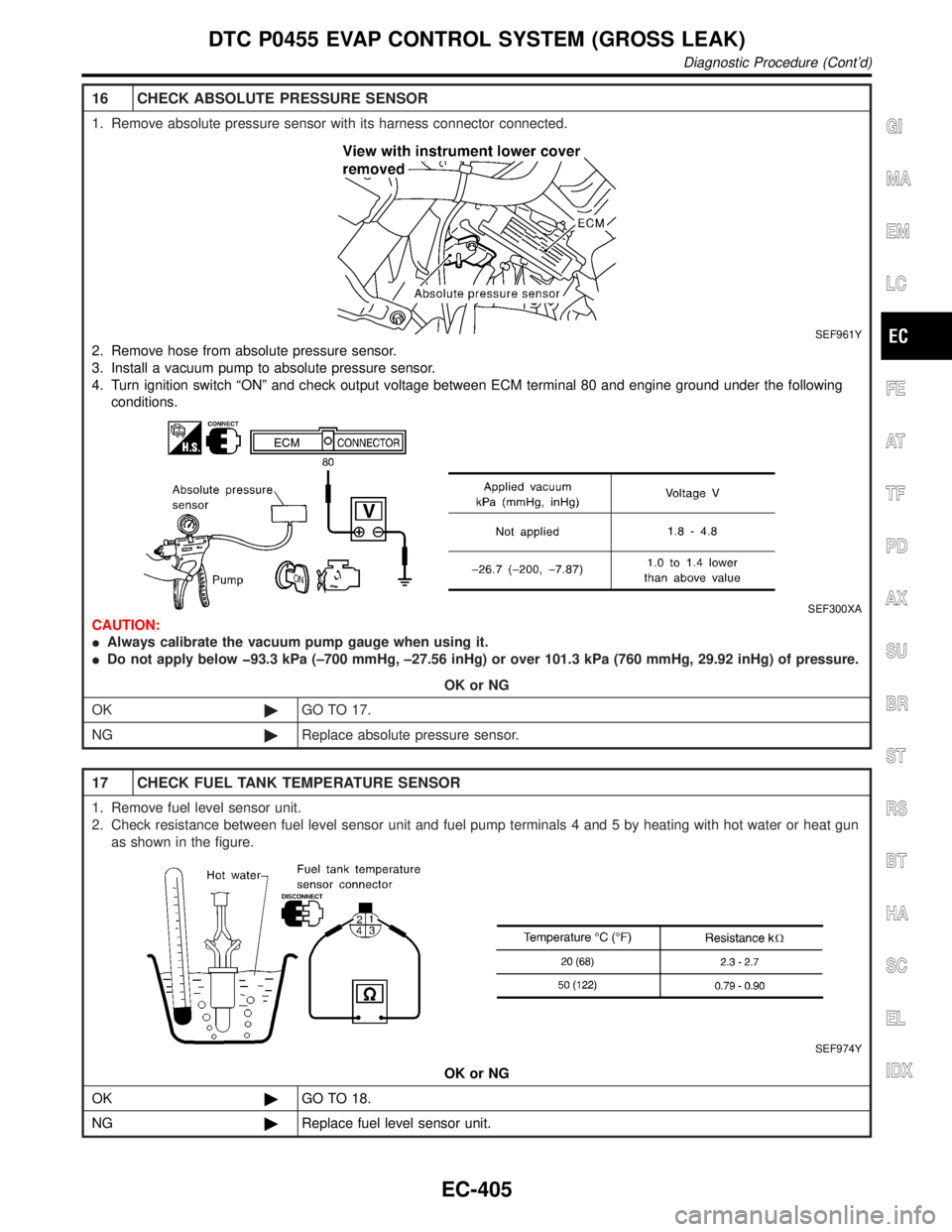
16 CHECK ABSOLUTE PRESSURE SENSOR
1. Remove absolute pressure sensor with its harness connector connected.
SEF961Y
2. Remove hose from absolute pressure sensor.
3. Install a vacuum pump to absolute pressure sensor.
4. Turn ignition switch ªONº and check output voltage between ECM terminal 80 and engine ground under the following
conditions.
SEF300XA
CAUTION:
IAlways calibrate the vacuum pump gauge when using it.
IDo not apply below þ93.3 kPa (±700 mmHg, ±27.56 inHg) or over 101.3 kPa (760 mmHg, 29.92 inHg) of pressure.
OK or NG
OK©GO TO 17.
NG©Replace absolute pressure sensor.
17 CHECK FUEL TANK TEMPERATURE SENSOR
1. Remove fuel level sensor unit.
2. Check resistance between fuel level sensor unit and fuel pump terminals 4 and 5 by heating with hot water or heat gun
as shown in the figure.
SEF974Y
OK or NG
OK©GO TO 18.
NG©Replace fuel level sensor unit.
GI
MA
EM
LC
FE
AT
TF
PD
AX
SU
BR
ST
RS
BT
HA
SC
EL
IDX
DTC P0455 EVAP CONTROL SYSTEM (GROSS LEAK)
Diagnostic Procedure (Cont'd)
EC-405
Page 941 of 2395

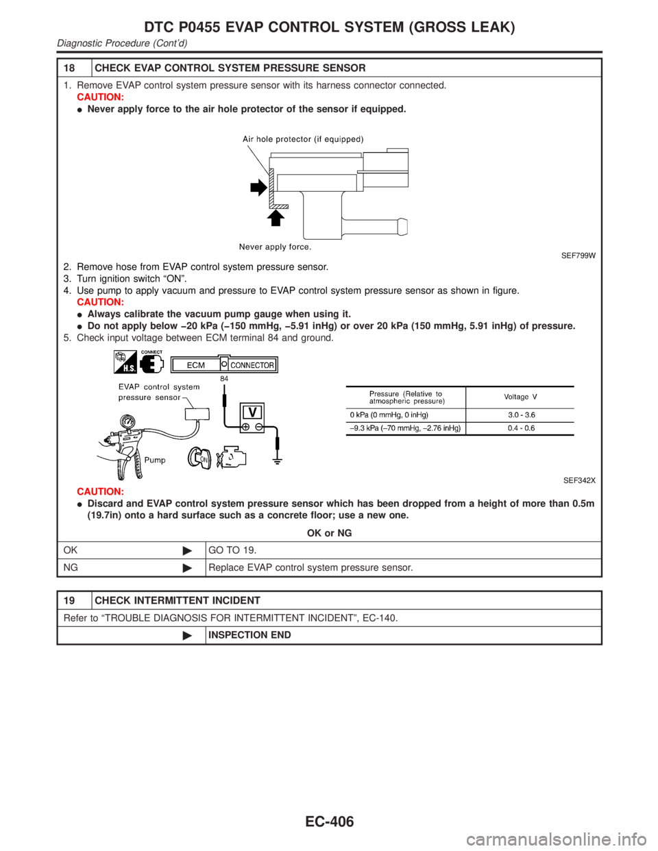
18 CHECK EVAP CONTROL SYSTEM PRESSURE SENSOR
1. Remove EVAP control system pressure sensor with its harness connector connected.
CAUTION:
INever apply force to the air hole protector of the sensor if equipped.
SEF799W
2. Remove hose from EVAP control system pressure sensor.
3. Turn ignition switch ªONº.
4. Use pump to apply vacuum and pressure to EVAP control system pressure sensor as shown in figure.
CAUTION:
IAlways calibrate the vacuum pump gauge when using it.
IDo not apply below þ20 kPa (þ150 mmHg, þ5.91 inHg) or over 20 kPa (150 mmHg, 5.91 inHg) of pressure.
5. Check input voltage between ECM terminal 84 and ground.
SEF342X
CAUTION:
IDiscard and EVAP control system pressure sensor which has been dropped from a height of more than 0.5m
(19.7in) onto a hard surface such as a concrete floor; use a new one.
OK or NG
OK©GO TO 19.
NG©Replace EVAP control system pressure sensor.
19 CHECK INTERMITTENT INCIDENT
Refer to ªTROUBLE DIAGNOSIS FOR INTERMITTENT INCIDENTº, EC-140.
©INSPECTION END
DTC P0455 EVAP CONTROL SYSTEM (GROSS LEAK)
Diagnostic Procedure (Cont'd)
EC-406
Page 944 of 2395

Diagnostic Procedure=NBEC0621
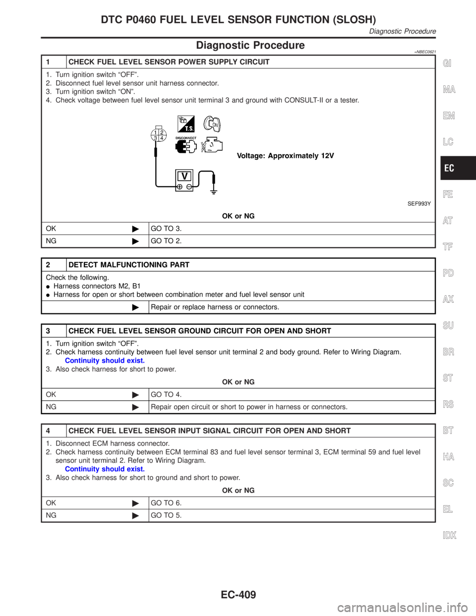
1 CHECK FUEL LEVEL SENSOR POWER SUPPLY CIRCUIT
1. Turn ignition switch ªOFFº.
2. Disconnect fuel level sensor unit harness connector.
3. Turn ignition switch ªONº.
4. Check voltage between fuel level sensor unit terminal 3 and ground with CONSULT-II or a tester.
SEF993Y
OK or NG
OK©GO TO 3.
NG©GO TO 2.
2 DETECT MALFUNCTIONING PART
Check the following.
IHarness connectors M2, B1
IHarness for open or short between combination meter and fuel level sensor unit
©Repair or replace harness or connectors.
3 CHECK FUEL LEVEL SENSOR GROUND CIRCUIT FOR OPEN AND SHORT
1. Turn ignition switch ªOFFº.
2. Check harness continuity between fuel level sensor unit terminal 2 and body ground. Refer to Wiring Diagram.
Continuity should exist.
3. Also check harness for short to power.
OK or NG
OK©GO TO 4.
NG©Repair open circuit or short to power in harness or connectors.
4 CHECK FUEL LEVEL SENSOR INPUT SIGNAL CIRCUIT FOR OPEN AND SHORT
1. Disconnect ECM harness connector.
2. Check harness continuity between ECM terminal 83 and fuel level sensor terminal 3, ECM terminal 59 and fuel level
sensor unit terminal 2. Refer to Wiring Diagram.
Continuity should exist.
3. Also check harness for short to ground and short to power.
OK or NG
OK©GO TO 6.
NG©GO TO 5.
GI
MA
EM
LC
FE
AT
TF
PD
AX
SU
BR
ST
RS
BT
HA
SC
EL
IDX
DTC P0460 FUEL LEVEL SENSOR FUNCTION (SLOSH)
Diagnostic Procedure
EC-409
Page 950 of 2395

Diagnostic Procedure=NBEC0631
1 CHECK FUEL LEVEL SENSOR POWER SUPPLY CIRCUIT
1. Turn ignition switch ªOFFº.
2. Disconnect fuel level sensor unit harness connector.
3. Turn ignition switch ªONº.
4. Check voltage between fuel level sensor unit terminal 3 and ground, ECM terminal 83 and ground with CONSULT-II or
tester.
SEF374Z
OK or NG
OK©GO TO 3.
NG©GO TO 2.
2 DETECT MALFUNCTIONING PART
Check the following.
IHarness connectors M2, B1 and M94, F27
IHarness for open or short between combination meter and fuel level sensor unit
©Repair or replace harness or connectors.
3 CHECK FUEL LEVEL SENSOR GROUND CIRCUIT FOR OPEN AND SHORT
1. Turn ignition switch ªOFFº.
2. Check harness continuity between fuel level sensor unit terminal 2 and body ground. Refer to Wiring Diagram.
Continuity should exist.
3. Also check harness for short to power.
OK or NG
OK©GO TO 4.
NG©Repair open circuit or short to power in harness or connectors.
4 CHECK FUEL LEVEL SENSOR GROUND CIRCUIT FOR OPEN AND SHORT
1. Disconnect ECM harness connector.
2. Check harness continuity between ECM terminal 59 and fuel level sensor terminal 2. Refer to Wiring Diagram.
Continuity should exist.
3. Also check harness for short to power.
OK or NG
OK©GO TO 6.
NG©GO TO 5.
GI
MA
EM
LC
FE
AT
TF
PD
AX
SU
BR
ST
RS
BT
HA
SC
EL
IDX
DTC P0464 FUEL LEVEL SENSOR CIRCUIT
Diagnostic Procedure
EC-415
Page 953 of 2395

Possible CauseNBEC0514IHarness or connector
(The vehicle speed sensor circuit is open or shorted.)
IVehicle speed sensor
DTC Confirmation ProcedureNBEC0245CAUTION:
Always drive vehicle at a safe speed.
NOTE:
If ªDTC Confirmation Procedureº has been previously conducted,
always turn ignition switch ªOFFº and wait at least 10 seconds
before conducting the next test.
TESTING CONDITION:
Steps 1 and 2 may be conducted with the drive wheels lifted
in the shop or by driving the vehicle. If a road test is expected
to be easier, it is unnecessary to lift the vehicle.
SEF196Y
WITH CONSULT-IINBEC0245S011) Start engine (TCS switch ªOFFº).
2) Read ªVHCL SPEED SEº in ªDATA MONITORº mode with
CONSULT-II. The vehicle speed on CONSULT-II should
exceed 10 km/h (6 MPH) when rotating wheels with suitable
gear position.
If NG, go to ªDiagnostic Procedureº, EC-421.
If OK, go to following step.
3) Select ªDATA MONITORº mode with CONSULT-II.
4) Warm engine up to normal operating temperature.
5) Maintain the following conditions for at least 10 consecutive
seconds.
ENG SPEED 1,800 - 6,000 rpm
COOLAN TEMP/S More than 70ÉC (158ÉF)
B/FUEL SCHDL 5.5 - 14.0 msec
Selector lever Suitable position
PW/ST SIGNAL OFF
6) If 1st trip DTC is detected, go to ªDiagnostic Procedureº,
EC-421.
Overall Function CheckNBEC0246Use this procedure to check the overall function of the vehicle
speed sensor circuit. During this check, a 1st trip DTC might not
be confirmed.
WITH GSTNBEC0246S011) Lift up drive wheels.
2) Start engine.
3) Read vehicle speed sensor signal in ªMODE 1º with GST.
The vehicle speed sensor on GST should be able to exceed
DTC P0500 VEHICLE SPEED SENSOR (VSS)
Possible Cause
EC-418
Page 956 of 2395

Diagnostic ProcedureNBEC0248
1 CHECK VEHICLE SPEED SENSOR INPUT SIGNAL CIRCUIT FOR OPEN AND SHORT
1. Turn ignition switch ªOFFº.
2. Disconnect ECM harness connector and combination meter harness connector.
3. Check harness continuity between ECM terminal 86 and combination meter terminal 13.
Refer to Wiring Diagram.
Continuity should exist.
4. Also check harness for short to power.
OK or NG
OK©GO TO 3.
NG©GO TO 2.
2 DETECT MALFUNCTIONING PART
Check the following.
IHarness connectors M32, F23
IHarness for open or short between ECM and combination meter
©Repair open circuit or short to ground or short to power in harness or connectors.
3 CHECK SPEEDOMETER FUNCTION
Make sure that speedometer functions properly.
OK or NG
OK©GO TO 5.
NG©GO TO 4.
4 CHECK SPEEDOMETER CIRCUIT FOR OPEN AND SHORT
Check the following.
IHarness connectors M70, B50
IHarness for open or short between combination meter and vehicle speed sensor
IHarness for open or short between vehicle speed sensor and ECM
OK or NG
OK©Check combination meter and vehicle speed sensor. Refer to EL section.
NG©Repair open circuit or short to ground or short to power in harness or connectors.
5 CHECK INTERMITTENT INCIDENT
Refer to ªTROUBLE DIAGNOSIS FOR INTERMITTENT INCIDENTº, EC-140.
©INSPECTION END
GI
MA
EM
LC
FE
AT
TF
PD
AX
SU
BR
ST
RS
BT
HA
SC
EL
IDX
DTC P0500 VEHICLE SPEED SENSOR (VSS)
Diagnostic Procedure
EC-421
Page 958 of 2395

CONSULT-II Reference Value in Data Monitor
Mode
NBEC0250Specification data are reference values.
MONITOR ITEM CONDITION SPECIFICATION
IACV-AAC/VIEngine: After warming up
IAir conditioner switch: ªOFFº
IShift lever: ªNº
INo-loadIdle 14 - 20 step
2,000 rpm Ð
ECM Terminals and Reference ValueNBEC0670Specification data are reference values and are measured between each terminal and ground.
CAUTION:
Do not use ECM ground terminals when measuring input/output voltage. Doing so may result in dam-
age to the ECM's transistor. Use a ground other than ECM terminals, such as the ground.
TERMI-
NAL
NO.WIRE
COLORITEM CONDITION DATA (DC Voltage)
6
7
8
17PU/G
GY
Y
GY/LIACV-AAC valve[Engine is running]
IIdle speed0.1 - 14V
On Board Diagnosis LogicNBEC0252Malfunction is detected when
(Malfunction A)the IACV-AAC valve does not operate properly,
(Malfunction B)the IACV-AAC valve does not operate properly.
Possible CauseNBEC0515MALFUNCTION ANBEC0515S01IHarness or connectors
(The IACV-AAC valve circuit is open.)
IIACV-AAC valve
MALFUNCTION BNBEC0515S02IHarness or connectors
(The IACV-AAC valve circuit is shorted.)
IAir control valve (Power steering)
IIACV-AAC valve
DTC Confirmation ProcedureNBEC0253NOTE:
IIf ªDTC Confirmation Procedureº has been previously
conducted, always turn ignition switch ªOFFº and wait at least
10 seconds before conducting the next test.
IPerform ªPROCEDURE FOR MALFUNCTION Aº first. If 1st
trip DTC cannot be confirmed, perform ªPROCEDURE
FOR MALFUNCTION Bº.
GI
MA
EM
LC
FE
AT
TF
PD
AX
SU
BR
ST
RS
BT
HA
SC
EL
IDX
DTC P0505 IDLE AIR CONTROL VALVE (IACV) Ð AUXILIARY AIR CONTROL
(AAC) VALVE
CONSULT-II Reference Value in Data Monitor Mode
EC-423
Page 961 of 2395
Diagnostic ProcedureNBEC0255
1 CHECK IACV-AAC VALVE POWER SUPPLY CIRCUIT
1. Stop engine.
2. Disconnect IACV-AAC valve harness connector.
SEF994Y
3. Turn ignition switch ªONº.
4. Check voltage between IACV-AAC valve terminals 2, 5 and ground with CONSULT-II or tester.
SEF343X
OK or NG
OK©GO TO 3.
NG©GO TO 2.
2 DETECT MALFUNCTIONING PART
Check the following.
IHarness connectors E1, M1
IHarness connectors M33, F22
IHarness for open or short between IACV-AAC valve and ECM relay
©Repair harness or connectors.
DTC P0505 IDLE AIR CONTROL VALVE (IACV) Ð AUXILIARY AIR CONTROL
(AAC) VALVE
Diagnostic Procedure
EC-426