Page 1696 of 2395
SEM418G
ICheck that valve lifters on No. 1 cylinder are loose and valve
lifters on No. 4 are tight.
If not, turn crankshaft one revolution (360É) and align as above.
SEM893E
7. Check only those valves shown in the figure.
Crank
positionValve
No. 1 No. 2 No. 3 No. 4 No. 5 No. 6
INT EXH INT EXH INT EXH INT EXH INT EXH INT EXH
No. 1 TDCqqq q
SEM139D
IUsing a feeler gauge, measure clearance between valve lifter
and camshaft.
IRecord any valve clearance measurements which are out of
specification. They will be used later to determine the required
replacement adjusting shim.
Valve clearance for checking (Cold):
Intake
0.26 - 0.34 mm (0.010 - 0.013 in)
Exhaust
0.29 - 0.37 mm (0.011 - 0.015 in)
GI
MA
LC
EC
FE
AT
TF
PD
AX
SU
BR
ST
RS
BT
HA
SC
EL
IDX
CYLINDER HEAD
Valve Clearance (Cont'd)
EM-53
Page 1697 of 2395
SEM894E
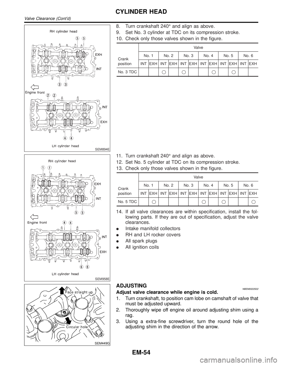
8. Turn crankshaft 240É and align as above.
9. Set No. 3 cylinder at TDC on its compression stroke.
10. Check only those valves shown in the figure.
Crank
positionValve
No. 1 No. 2 No. 3 No. 4 No. 5 No. 6
INT EXH INT EXH INT EXH INT EXH INT EXH INT EXH
No. 3 TDCqq qq
SEM958E
11. Turn crankshaft 240É and align as above.
12. Set No. 5 cylinder at TDC on its compression stroke.
13. Check only those valves shown in the figure.
Crank
positionValve
No. 1 No. 2 No. 3 No. 4 No. 5 No. 6
INT EXH INT EXH INT EXH INT EXH INT EXH INT EXH
No. 5 TDCqqqq
14. If all valve clearances are within specification, install the fol-
lowing parts. If they are out of specification, adjust the valve
clearances.
IIntake manifold collectors
IRH and LH rocker covers
IAll spark plugs
IAll ignition coils
SEM449G
ADJUSTINGNBEM0022S02Adjust valve clearance while engine is cold.
1. Turn crankshaft, to position cam lobe on camshaft of valve that
must be adjusted upward.
2. Thoroughly wipe off engine oil around adjusting shim using a
rag.
3. Using a extra-fine screwdriver, turn the round hole of the
adjusting shim in the direction of the arrow.
CYLINDER HEAD
Valve Clearance (Cont'd)
EM-54
Page 1700 of 2395
Removal and InstallationNBEM0042WARNING:
ISituate vehicle on a flat and solid surface.
IPlace chocks at front and back of rear wheels.
IDo not remove engine until exhaust system has com-
pletely cooled off. Otherwise, you may burn yourself
and/or fire may break out in fuel line.
IFor safety during subsequent steps, the tension of wires
should be slackened against the engine.
IBefore disconnecting fuel hose, release fuel pressure
from fuel line.
Refer to EC-39, ªFuel Pressure Releaseº.
IBefore removing front axle from transmission, place
safety stands under designated front supporting points.
Refer to GI section for lifting points and towing.
IBe sure to hoist engine and transmission in a safe man-
ner.
IFor engines not equipped with engine slingers, attach
proper slingers and bolts described in PARTS CATALOG.
CAUTION:
IWhen lifting engine, be careful not to strike adjacent parts,
especially accelerator wire casing, brake lines, and brake
master cylinder.
IIn hoisting the engine, always use engine slingers in a
safe manner.
IBefore separating engine and transmission, remove
crankshaft position sensor (POS) from the assembly.
IAlways take extra care not to damage edge of crankshaft
position sensor (POS), or ring gear teeth.GI
MA
LC
EC
FE
AT
TF
PD
AX
SU
BR
ST
RS
BT
HA
SC
EL
IDX
ENGINE ASSEMBLY
Removal and Installation
EM-57
Page 1706 of 2395
SEM965A
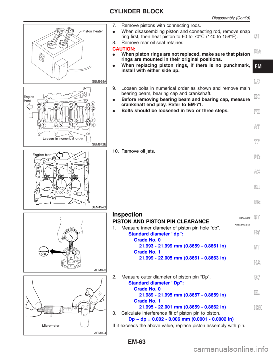
7. Remove pistons with connecting rods.
IWhen disassembling piston and connecting rod, remove snap
ring first, then heat piston to 60 to 70ÉC (140 to 158ÉF).
8. Remove rear oil seal retainer.
CAUTION:
IWhen piston rings are not replaced, make sure that piston
rings are mounted in their original positions.
IWhen replacing piston rings, if there is no punchmark,
install with either side up.
SEM842E
9. Loosen bolts in numerical order as shown and remove main
bearing beam, bearing cap and crankshaft.
IBefore removing bearing beam and bearing cap, measure
crankshaft end play. Refer to EM-71.
IBolts should be loosened in two or three steps.
SEM454G
10. Remove oil jets.
AEM023
InspectionNBEM0027PISTON AND PISTON PIN CLEARANCENBEM0027S011. Measure inner diameter of piston pin hole ªdpº.
Standard diameter ªdpº:
Grade No. 0
21.993 - 21.999 mm (0.8659 - 0.8661 in)
Grade No. 1
21.999 - 22.005 mm (0.8661 - 0.8663 in)
AEM024
2. Measure outer diameter of piston pin ªDpº.
Standard diameter ªDpº:
Grade No. 0
21.989 - 21.995 mm (0.8657 - 0.8659 in)
Grade No. 1
21.995 - 22.001 mm (0.8659 - 0.8662 in)
3. Calculate interference fit of piston pin to piston.
Dp þ dp = 0.002 - 0.006 mm (0.0001 - 0.0002 in)
If it exceeds the above value, replace piston assembly with pin.
GI
MA
LC
EC
FE
AT
TF
PD
AX
SU
BR
ST
RS
BT
HA
SC
EL
IDX
CYLINDER BLOCK
Disassembly (Cont'd)
EM-63
Page 1708 of 2395
SEM038F
SEM003F
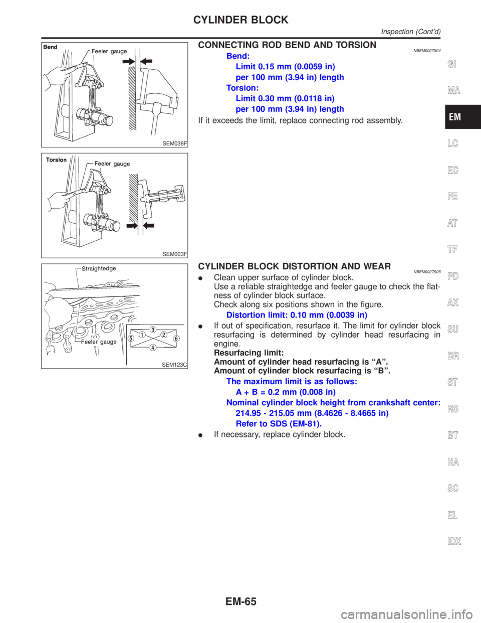
CONNECTING ROD BEND AND TORSIONNBEM0027S04Bend:
Limit 0.15 mm (0.0059 in)
per 100 mm (3.94 in) length
Torsion:
Limit 0.30 mm (0.0118 in)
per 100 mm (3.94 in) length
If it exceeds the limit, replace connecting rod assembly.
SEM123C
CYLINDER BLOCK DISTORTION AND WEARNBEM0027S05IClean upper surface of cylinder block.
Use a reliable straightedge and feeler gauge to check the flat-
ness of cylinder block surface.
Check along six positions shown in the figure.
Distortion limit: 0.10 mm (0.0039 in)
IIf out of specification, resurface it. The limit for cylinder block
resurfacing is determined by cylinder head resurfacing in
engine.
Resurfacing limit:
Amount of cylinder head resurfacing is ªAº.
Amount of cylinder block resurfacing is ªBº.
The maximum limit is as follows:
A + B = 0.2 mm (0.008 in)
Nominal cylinder block height from crankshaft center:
214.95 - 215.05 mm (8.4626 - 8.4665 in)
Refer to SDS (EM-81).
IIf necessary, replace cylinder block.
GI
MA
LC
EC
FE
AT
TF
PD
AX
SU
BR
ST
RS
BT
HA
SC
EL
IDX
CYLINDER BLOCK
Inspection (Cont'd)
EM-65
Page 1710 of 2395
8. Cut cylinder bores.
IWhen any cylinder needs boring, all other cylinders must
also be bored.
IDo not cut too much out of cylinder bore at a time. Cut
only 0.05 mm (0.0020 in) or so in diameter at a time.
9. Hone cylinders to obtain specified piston-to-bore clearance.
10. Measure finished cylinder bore for out-of-round and taper.
IMeasurement should be done after cylinder bore cools
down.
SEM316A
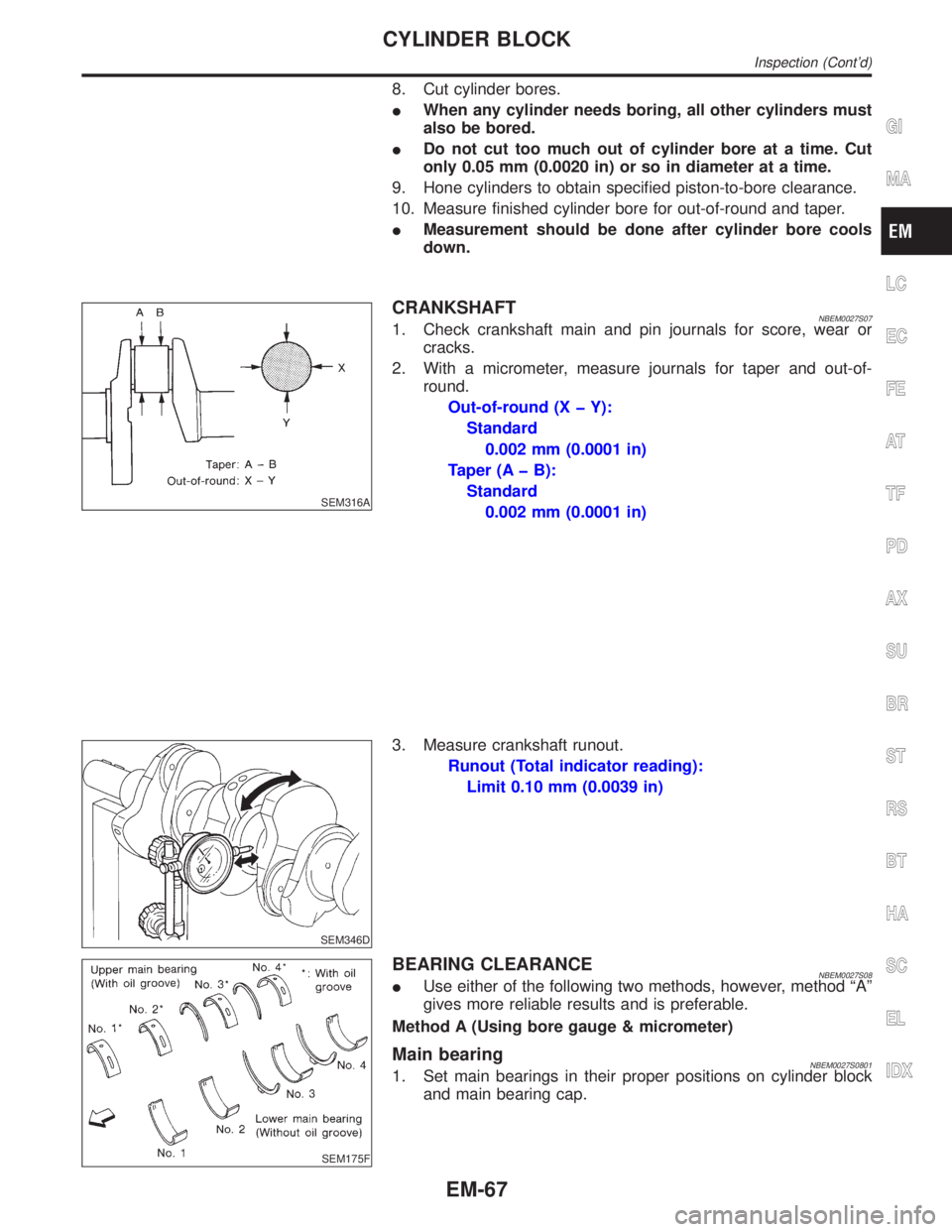
CRANKSHAFTNBEM0027S071. Check crankshaft main and pin journals for score, wear or
cracks.
2. With a micrometer, measure journals for taper and out-of-
round.
Out-of-round (X þ Y):
Standard
0.002 mm (0.0001 in)
Taper (A þ B):
Standard
0.002 mm (0.0001 in)
SEM346D
3. Measure crankshaft runout.
Runout (Total indicator reading):
Limit 0.10 mm (0.0039 in)
SEM175F
BEARING CLEARANCENBEM0027S08IUse either of the following two methods, however, method ªAº
gives more reliable results and is preferable.
Method A (Using bore gauge & micrometer)
Main bearingNBEM0027S08011. Set main bearings in their proper positions on cylinder block
and main bearing cap.
GI
MA
LC
EC
FE
AT
TF
PD
AX
SU
BR
ST
RS
BT
HA
SC
EL
IDX
CYLINDER BLOCK
Inspection (Cont'd)
EM-67
Page 1714 of 2395
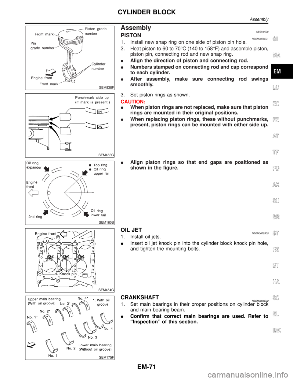
SEM838F
AssemblyNBEM0028PISTONNBEM0028S011. Install new snap ring on one side of piston pin hole.
2. Heat piston to 60 to 70ÉC (140 to 158ÉF) and assemble piston,
piston pin, connecting rod and new snap ring.
IAlign the direction of piston and connecting rod.
INumbers stamped on connecting rod and cap correspond
to each cylinder.
IAfter assembly, make sure connecting rod swings
smoothly.
SEM453G
3. Set piston rings as shown.
CAUTION:
IWhen piston rings are not replaced, make sure that piston
rings are mounted in their original positions.
IWhen replacing piston rings, these without punchmarks,
present, piston rings can be mounted with either side up.
SEM160B
IAlign piston rings so that end gaps are positioned as
shown in the figure.
SEM454G
OIL JETNBEM0028S051. Install oil jets.
IInsert oil jet knock pin into the cylinder block knock pin hole,
and tighten the mounting bolts.
SEM175F
CRANKSHAFTNBEM0028S021. Set main bearings in their proper positions on cylinder block
and main bearing beam.
IConfirm that correct main bearings are used. Refer to
ªInspectionº of this section.
GI
MA
LC
EC
FE
AT
TF
PD
AX
SU
BR
ST
RS
BT
HA
SC
EL
IDX
CYLINDER BLOCK
Assembly
EM-71
Page 1715 of 2395
SEM177F
SEM456G
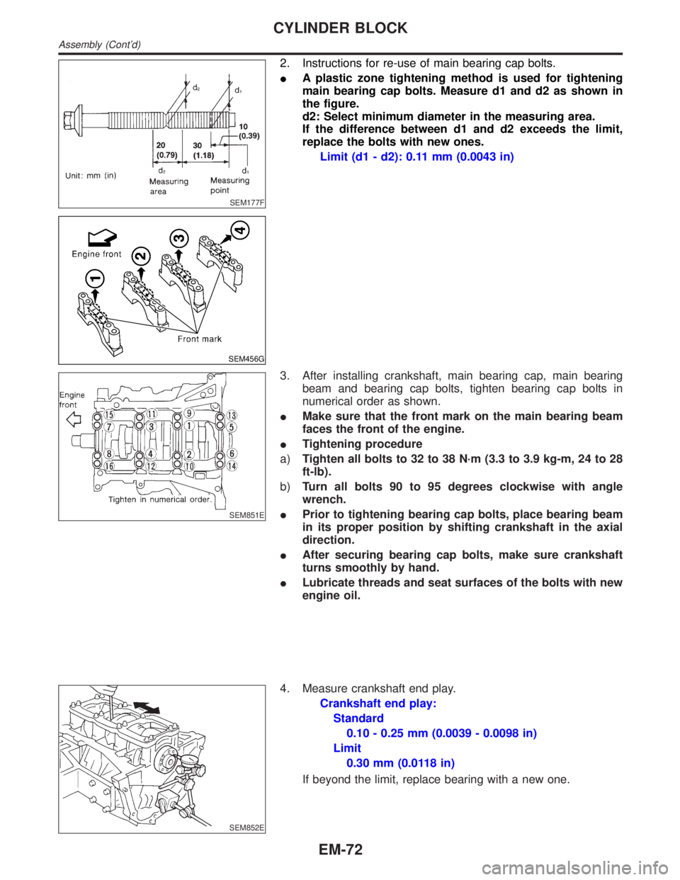
2. Instructions for re-use of main bearing cap bolts.
IA plastic zone tightening method is used for tightening
main bearing cap bolts. Measure d1 and d2 as shown in
the figure.
d2: Select minimum diameter in the measuring area.
If the difference between d1 and d2 exceeds the limit,
replace the bolts with new ones.
Limit (d1 - d2): 0.11 mm (0.0043 in)
SEM851E
3. After installing crankshaft, main bearing cap, main bearing
beam and bearing cap bolts, tighten bearing cap bolts in
numerical order as shown.
IMake sure that the front mark on the main bearing beam
faces the front of the engine.
ITightening procedure
a)Tighten all bolts to 32 to 38 N´m (3.3 to 3.9 kg-m, 24 to 28
ft-lb).
b)Turn all bolts 90 to 95 degrees clockwise with angle
wrench.
IPrior to tightening bearing cap bolts, place bearing beam
in its proper position by shifting crankshaft in the axial
direction.
IAfter securing bearing cap bolts, make sure crankshaft
turns smoothly by hand.
ILubricate threads and seat surfaces of the bolts with new
engine oil.
SEM852E
4. Measure crankshaft end play.
Crankshaft end play:
Standard
0.10 - 0.25 mm (0.0039 - 0.0098 in)
Limit
0.30 mm (0.0118 in)
If beyond the limit, replace bearing with a new one.
CYLINDER BLOCK
Assembly (Cont'd)
EM-72