2001 FORD WINDSTAR brake sensor
[x] Cancel search: brake sensorPage 23 of 288
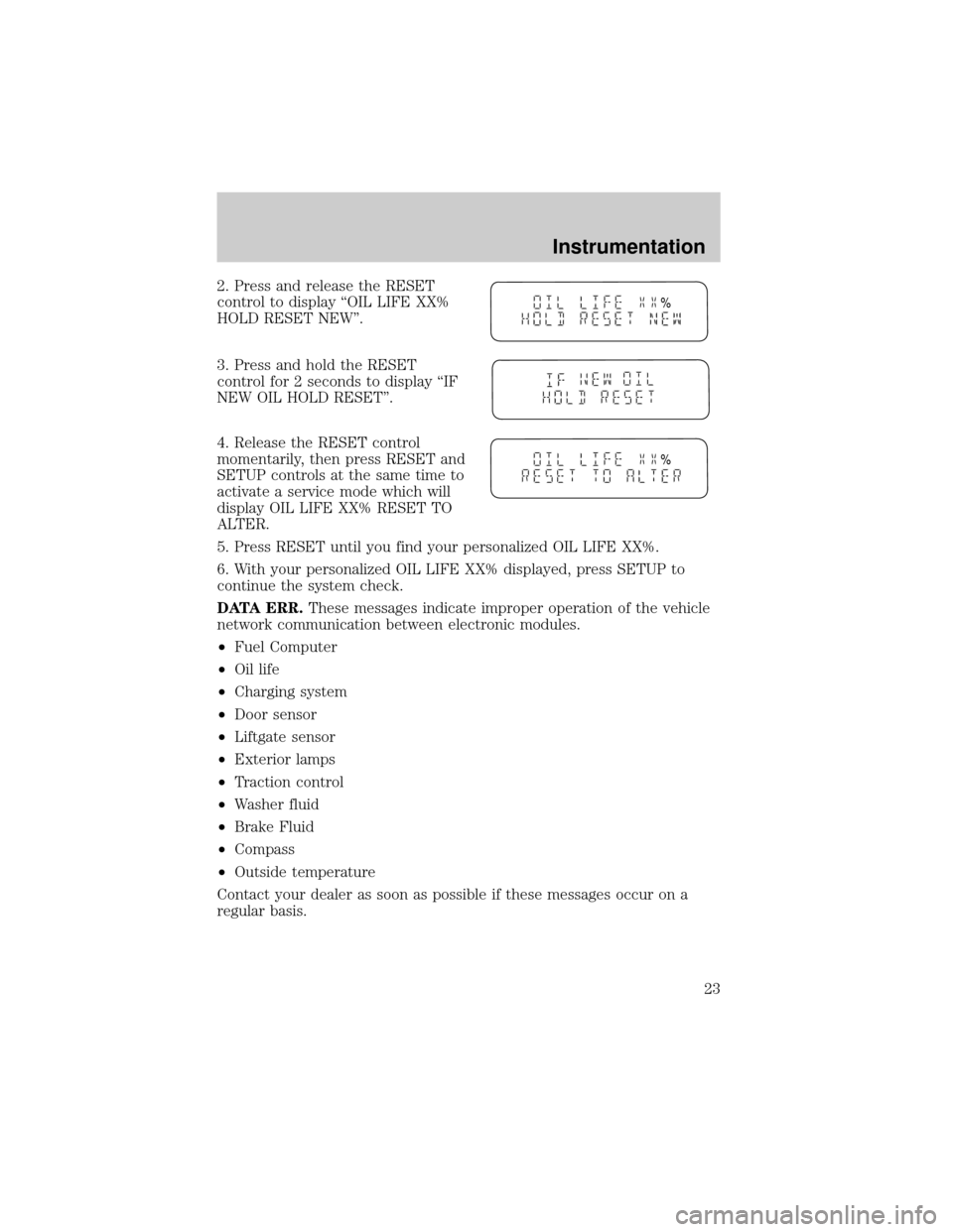
2. Press and release the RESET
control to display ªOIL LIFE XX%
HOLD RESET NEW''.
3. Press and hold the RESET
control for 2 seconds to display ªIF
NEW OIL HOLD RESET''.
4. Release the RESET control
momentarily, then press RESET and
SETUP controls at the same time to
activate a service mode which will
display OIL LIFE XX% RESET TO
ALTER.
5. Press RESET until you find your personalized OIL LIFE XX%.
6. With your personalized OIL LIFE XX% displayed, press SETUP to
continue the system check.
DATA ERR.These messages indicate improper operation of the vehicle
network communication between electronic modules.
²Fuel Computer
²Oil life
²Charging system
²Door sensor
²Liftgate sensor
²Exterior lamps
²Traction control
²Washer fluid
²Brake Fluid
²Compass
²Outside temperature
Contact your dealer as soon as possible if these messages occur on a
regular basis.
%
%
Instrumentation
23
Page 144 of 288
Replacing the front passenger and second row bench seat belt
assemblies after a collision
All front passenger and second row bench seat belt assemblies adjacent
to a sliding door have special energy management retractors designed to
further reduce the risk of injury in the event of a head-on collision.
These retractors should be replaced if they were used in any accident in
which the front airbags deploy. If the safety belt assemblies are not
replaced, there may be increased risk of injury in the event of a
subsequent collision.
Failure to inspect and if necessary replace the safety belt
assembly under the above conditions could result in severe
personal injuries in the event of a collision.
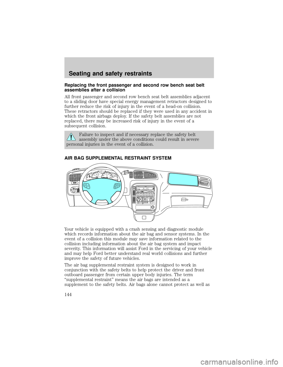
AIR BAG SUPPLEMENTAL RESTRAINT SYSTEM
Your vehicle is equipped with a crash sensing and diagnostic module
which records information about the air bag and sensor systems. In the
event of a collision this module may save information related to the
collision including information about the air bag system and impact
severity. This information will assist Ford in the servicing of your vehicle
and may help Ford better understand real world collisions and further
improve the safety of future vehicles.
The air bag supplemental restraint system is designed to work in
conjunction with the safety belts to help protect the driver and front
outboard passenger from certain upper body injuries. The term
ªsupplemental restraintº means the air bags are intended as a
supplement to the safety belts. Air bags alone cannot protect as well as
FM 1
AMC
BL RF ST
mi
AUTOP
12345
6
7RPMX1000 THEFT TRAC
ACTIVE TRAC
OFFFFUEL
E404080
120
1602060
80100 MPHTEMP
Hkm/hBRAKEO/D
OFFO
/D
O
N
/O
FFINFOSETUP
RESET
DISC
EJMUTEVOL - PUSH ONOFF
T/C
REW FFSCAN
BASS TREB SEL BALTAPE EJ CD
FADEAUTO
CLK
SIDE 1-2 COMP SHUFFLESEEK
TUNE AM FM12 3456DOLBY B NR
A/CFRONT
REAR
OFFMAX
A/C
REAR
CONT
ONSET+RESCST-OFF
Seating and safety restraints
144
Page 169 of 288
The BRAKE warning lamp in the
instrument cluster illuminates and
remains illuminated (when the
ignition is turned ON) until the
parking brake is released.
The parking brake is not recommended to stop a moving vehicle.
However, if the normal brakes fail, the parking brake can be used to stop
your vehicle in an emergency. Since the parking brake applies only the
rear brakes, the vehicle's stopping distance will increase greatly and the
handling of your vehicle will be adversely affected.
Always set the parking brake fully and make sure that the
gearshift is securely latched in P (Park) (automatic transaxle).
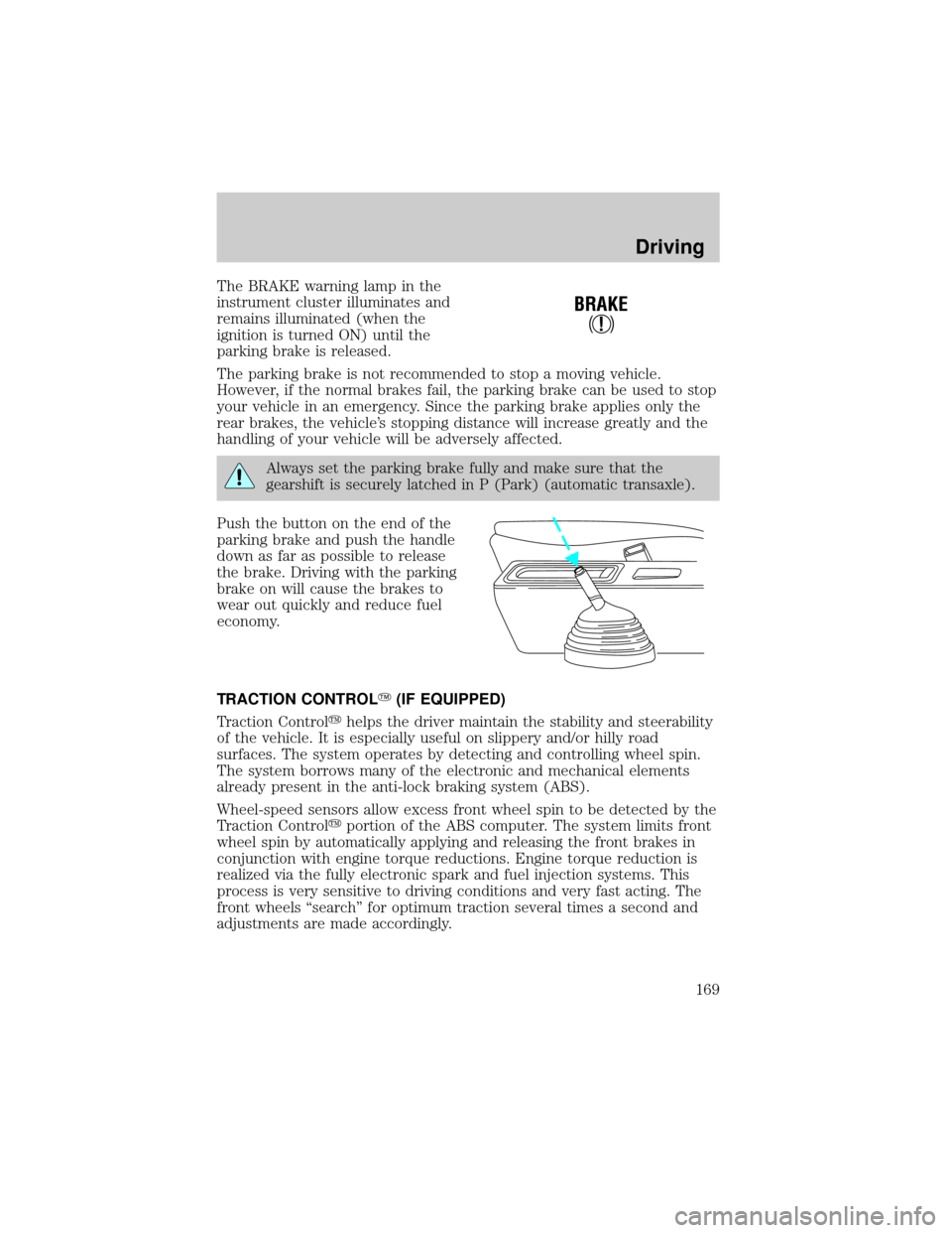
Push the button on the end of the
parking brake and push the handle
down as far as possible to release
the brake. Driving with the parking
brake on will cause the brakes to
wear out quickly and reduce fuel
economy.
TRACTION CONTROLY(IF EQUIPPED)
Traction Controlyhelps the driver maintain the stability and steerability
of the vehicle. It is especially useful on slippery and/or hilly road
surfaces. The system operates by detecting and controlling wheel spin.
The system borrows many of the electronic and mechanical elements
already present in the anti-lock braking system (ABS).
Wheel-speed sensors allow excess front wheel spin to be detected by the
Traction Controlyportion of the ABS computer. The system limits front
wheel spin by automatically applying and releasing the front brakes in
conjunction with engine torque reductions. Engine torque reduction is
realized via the fully electronic spark and fuel injection systems. This
process is very sensitive to driving conditions and very fast acting. The
front wheels ªsearchº for optimum traction several times a second and
adjustments are made accordingly.
!
BRAKE
Driving
169
Page 170 of 288
The Traction Controlysystem will assist you in making better use of
available traction on slippery surfaces. The system is a driver aid which
makes your vehicle easier to handle primarily on snow and ice covered
roads.
During Traction Controlyoperation, TRACTION CONTROL OK is
displayed on the message center (if equipped). You may hear an electric
motor type of sound coming from the engine compartment and the
engine will not ªrev-upº when you push further on the accelerator. This
is normal system behavior.
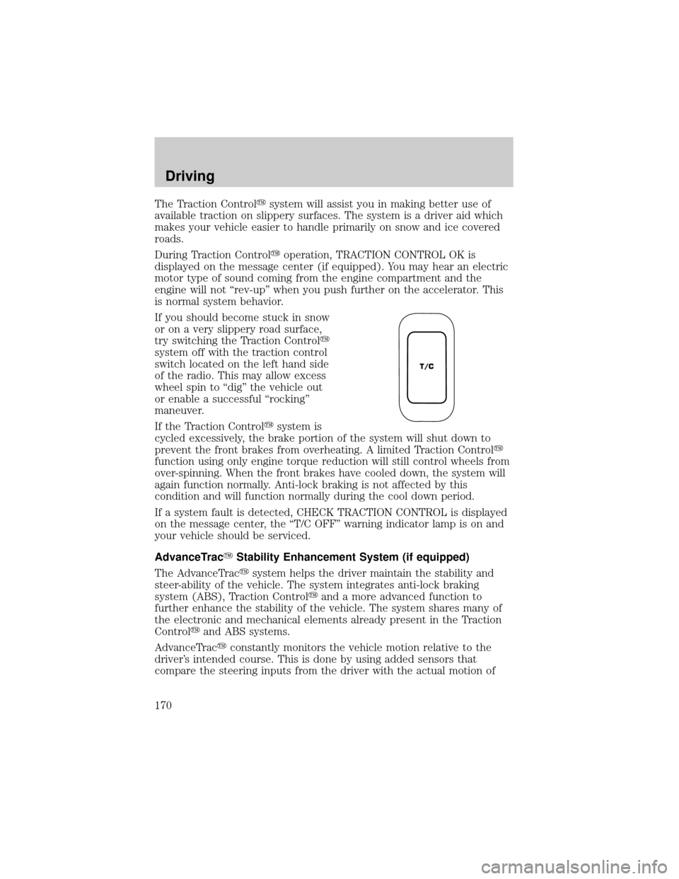
If you should become stuck in snow
or on a very slippery road surface,
try switching the Traction Controly
system off with the traction control
switch located on the left hand side
of the radio. This may allow excess
wheel spin to ªdigº the vehicle out
or enable a successful ªrockingº
maneuver.
If the Traction Controlysystem is
cycled excessively, the brake portion of the system will shut down to
prevent the front brakes from overheating. A limited Traction Controly
function using only engine torque reduction will still control wheels from
over-spinning. When the front brakes have cooled down, the system will
again function normally. Anti-lock braking is not affected by this
condition and will function normally during the cool down period.
If a system fault is detected, CHECK TRACTION CONTROL is displayed
on the message center, the ªT/C OFFº warning indicator lamp is on and
your vehicle should be serviced.
AdvanceTracYStability Enhancement System (if equipped)
The AdvanceTracysystem helps the driver maintain the stability and
steer-ability of the vehicle. The system integrates anti-lock braking
system (ABS), Traction Controlyand a more advanced function to
further enhance the stability of the vehicle. The system shares many of
the electronic and mechanical elements already present in the Traction
Controlyand ABS systems.
AdvanceTracyconstantly monitors the vehicle motion relative to the
driver's intended course. This is done by using added sensors that
compare the steering inputs from the driver with the actual motion of
T/C
Driving
170
Page 172 of 288
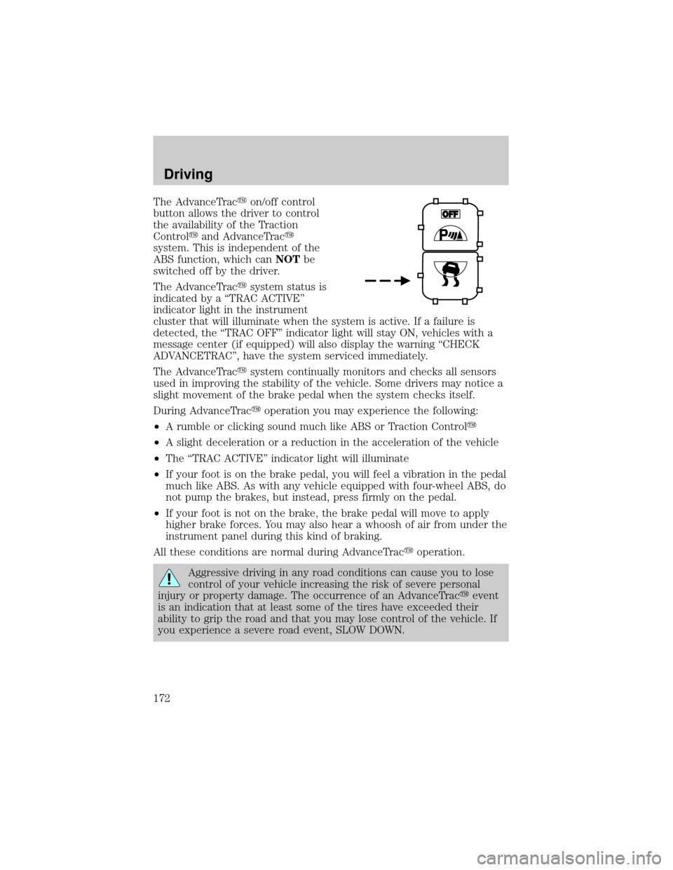
The AdvanceTracyon/off control
button allows the driver to control
the availability of the Traction
Controlyand AdvanceTracy
system. This is independent of the
ABS function, which canNOTbe
switched off by the driver.
The AdvanceTracysystem status is
indicated by a ªTRAC ACTIVEº
indicator light in the instrument
cluster that will illuminate when the system is active. If a failure is
detected, the ªTRAC OFFº indicator light will stay ON, vehicles with a
message center (if equipped) will also display the warning ªCHECK
ADVANCETRACº, have the system serviced immediately.
The AdvanceTracysystem continually monitors and checks all sensors
used in improving the stability of the vehicle. Some drivers may notice a
slight movement of the brake pedal when the system checks itself.
During AdvanceTracyoperation you may experience the following:
²A rumble or clicking sound much like ABS or Traction Controly
²A slight deceleration or a reduction in the acceleration of the vehicle
²The ªTRAC ACTIVEº indicator light will illuminate
²If your foot is on the brake pedal, you will feel a vibration in the pedal
much like ABS. As with any vehicle equipped with four-wheel ABS, do
not pump the brakes, but instead, press firmly on the pedal.
²If your foot is not on the brake, the brake pedal will move to apply
higher brake forces. You may also hear a whoosh of air from under the
instrument panel during this kind of braking.
All these conditions are normal during AdvanceTracyoperation.
Aggressive driving in any road conditions can cause you to lose
control of your vehicle increasing the risk of severe personal
injury or property damage. The occurrence of an AdvanceTracyevent
is an indication that at least some of the tires have exceeded their
ability to grip the road and that you may lose control of the vehicle. If
you experience a severe road event, SLOW DOWN.
Driving
172
Page 191 of 288
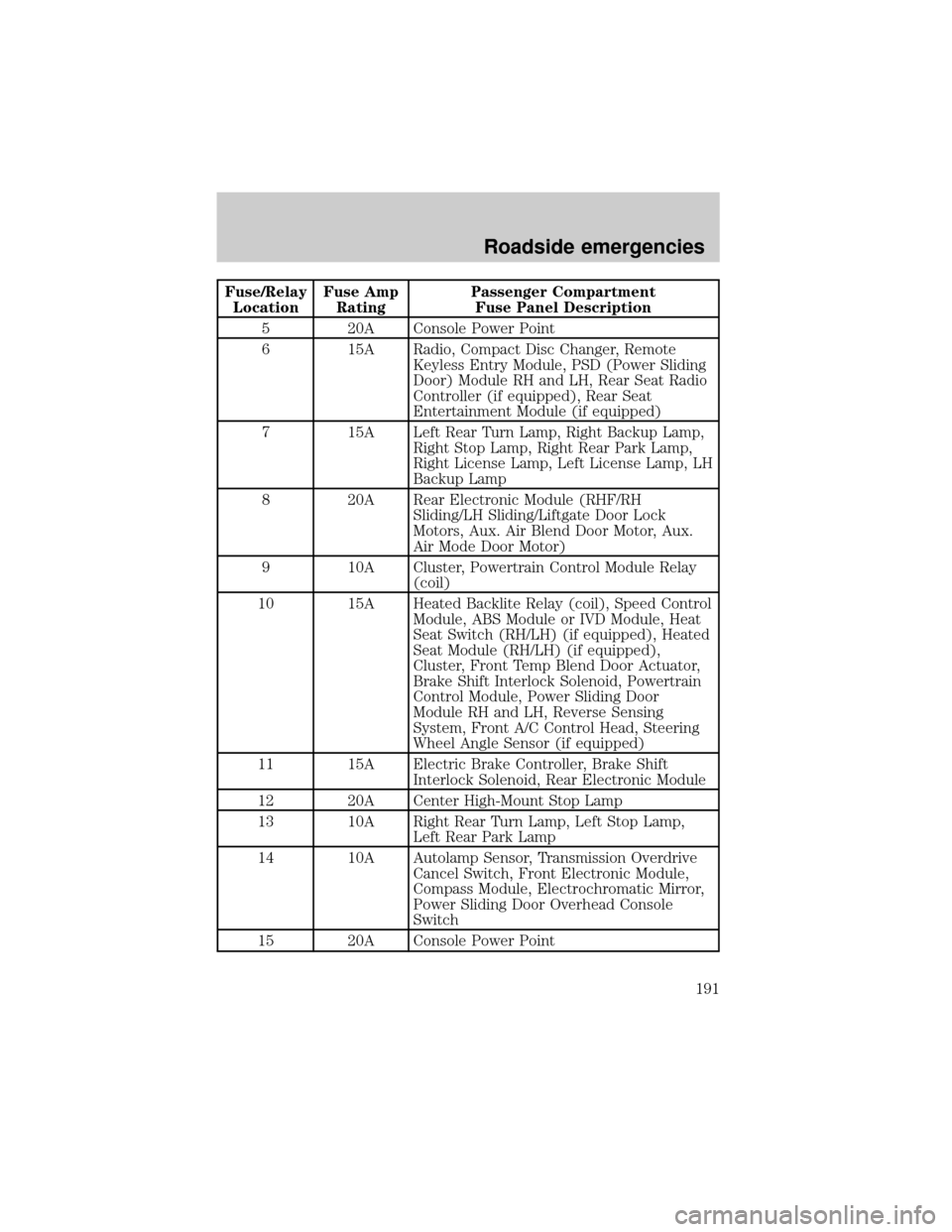
Fuse/Relay
LocationFuse Amp
RatingPassenger Compartment
Fuse Panel Description
5 20A Console Power Point
6 15A Radio, Compact Disc Changer, Remote
Keyless Entry Module, PSD (Power Sliding
Door) Module RH and LH, Rear Seat Radio
Controller (if equipped), Rear Seat
Entertainment Module (if equipped)
7 15A Left Rear Turn Lamp, Right Backup Lamp,
Right Stop Lamp, Right Rear Park Lamp,
Right License Lamp, Left License Lamp, LH
Backup Lamp
8 20A Rear Electronic Module (RHF/RH
Sliding/LH Sliding/Liftgate Door Lock
Motors, Aux. Air Blend Door Motor, Aux.
Air Mode Door Motor)
9 10A Cluster, Powertrain Control Module Relay
(coil)
10 15A Heated Backlite Relay (coil), Speed Control
Module, ABS Module or IVD Module, Heat
Seat Switch (RH/LH) (if equipped), Heated
Seat Module (RH/LH) (if equipped),
Cluster, Front Temp Blend Door Actuator,
Brake Shift Interlock Solenoid, Powertrain
Control Module, Power Sliding Door
Module RH and LH, Reverse Sensing
System, Front A/C Control Head, Steering
Wheel Angle Sensor (if equipped)
11 15A Electric Brake Controller, Brake Shift
Interlock Solenoid, Rear Electronic Module
12 20A Center High-Mount Stop Lamp
13 10A Right Rear Turn Lamp, Left Stop Lamp,
Left Rear Park Lamp
14 10A Autolamp Sensor, Transmission Overdrive
Cancel Switch, Front Electronic Module,
Compass Module, Electrochromatic Mirror,
Power Sliding Door Overhead Console
Switch
15 20A Console Power Point
Roadside emergencies
191
Page 232 of 288
which all passenger car tires must meet under the Federal Motor Vehicle
Safety Standard No. 109. Grades B and A represent higher levels of
performance on the laboratory test wheel than the minimum required by
law.
The temperature grade for this tire is established for a tire that
is properly inflated and not overloaded. Excessive speed,
underinflation, or excessive loading, either separately or in
combination, can cause heat buildup and possible tire failure.
SERVICING YOUR TIRES
Low tire warning (if equipped)
The low tire warning system is designed to detect a significant loss of
inflation inany one of your tireson your vehicle. The system uses the
Anti-lock brake wheel speed sensors to detect a change in wheel speed
due to tire deflation.
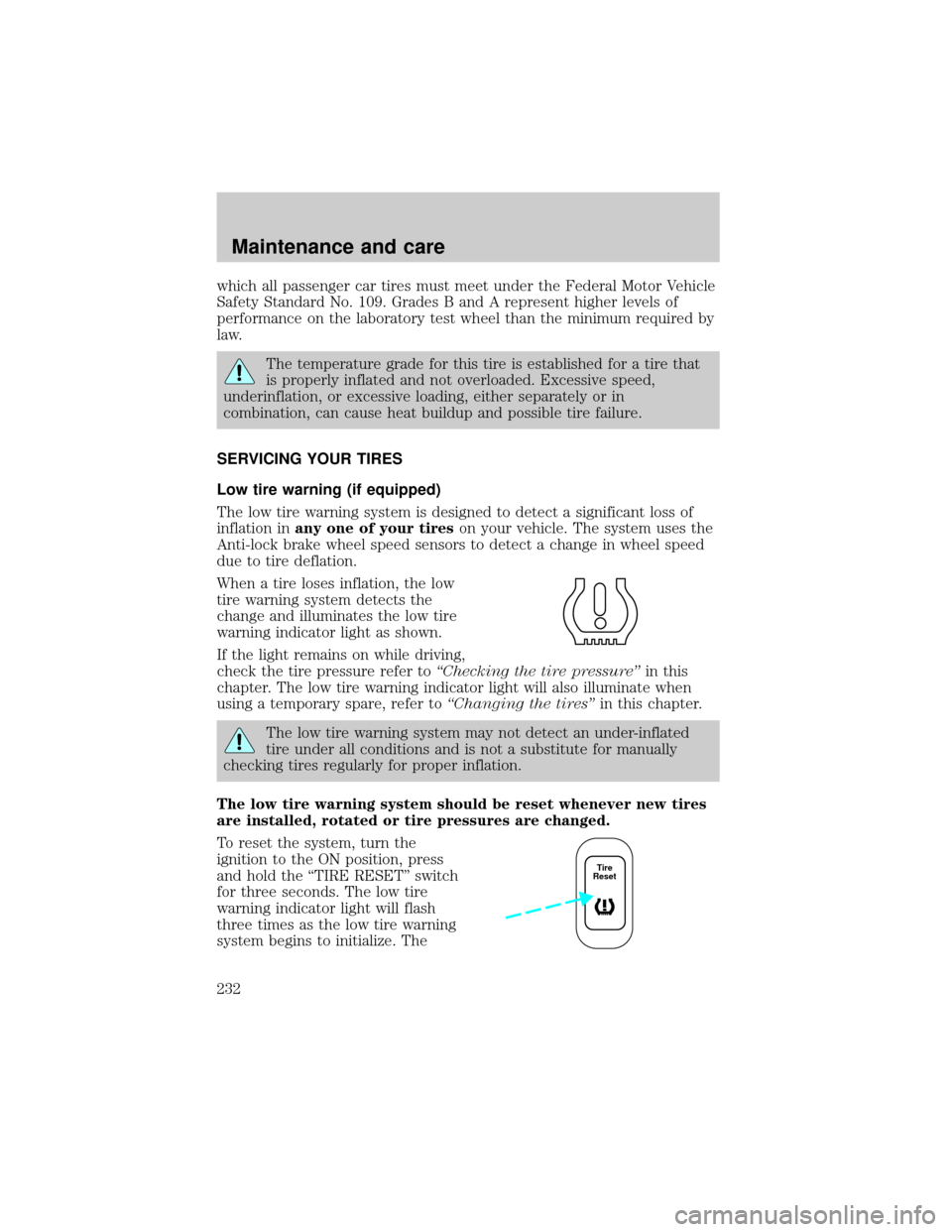
When a tire loses inflation, the low
tire warning system detects the
change and illuminates the low tire
warning indicator light as shown.
If the light remains on while driving,
check the tire pressure refer toªChecking the tire pressureºin this
chapter. The low tire warning indicator light will also illuminate when
using a temporary spare, refer toªChanging the tiresºin this chapter.
The low tire warning system may not detect an under-inflated
tire under all conditions and is not a substitute for manually
checking tires regularly for proper inflation.
The low tire warning system should be reset whenever new tires
are installed, rotated or tire pressures are changed.
To reset the system, turn the
ignition to the ON position, press
and hold the ªTIRE RESETº switch
for three seconds. The low tire
warning indicator light will flash
three times as the low tire warning
system begins to initialize. The
Tire
Reset
Maintenance and care
232
Page 282 of 288

Load limits .................................178
GAWR ......................................178
GVWR ......................................178
trailer towing ..........................178
Locks
autolock ...................................110
childproof ..................................88
Lubricant specifications ...259, 261
Lumbar support, seats .............122
M
Message center ...........................17
english/metric button ...............18
system check button ................18
warning messages .....................19
Mirrors .........................................90
automatic dimming rearview
mirror ........................................89
cleaning ...................................254
fold away ...................................87
heated ........................................87
programmable memory ..........109
side view mirrors (power) .......86
Motorcraft parts ................240, 257
O
Octane rating ............................239
Odometer .....................................16
Oil (see Engine oil) ..................211
Overdrive .............................83, 174
P
Panic alarm feature,
remote entry system ................106
Parking brake ............................168Parts (see Motorcraft parts) ....257
Passenger Occupant
Classification Sensor .................132
Pedals (see Power
adjustable foot pedals) ...............78
Power adjustable foot pedals .....78
Power distribution box
(see Fuses) ...............................192
Power door locks ................88, 110
Power steering ..........................173
fluid, checking and adding ....221
fluid, refill capacity ................258
fluid, specifications .........259, 261
R
Radio ............................................39
Relays ........................................187
Remote entry system .......102, 106
illuminated entry ......28, 107, 110
locking/
unlocking doors ..............103±105
panic alarm .............................106
replacement/additional
transmitters .............................108
replacing the batteries ...........107
Reverse sensing system .............75
Roof rack ...................................184
S
Safety belts (see Safety
restraints) ....14, 131, 134±137, 139
Safety defects, reporting ..........277
Safety
restraints ...........131, 134±137, 139
belt minder .............................140
Index
282