2001 FORD WINDSTAR AUX
[x] Cancel search: AUXPage 116 of 288
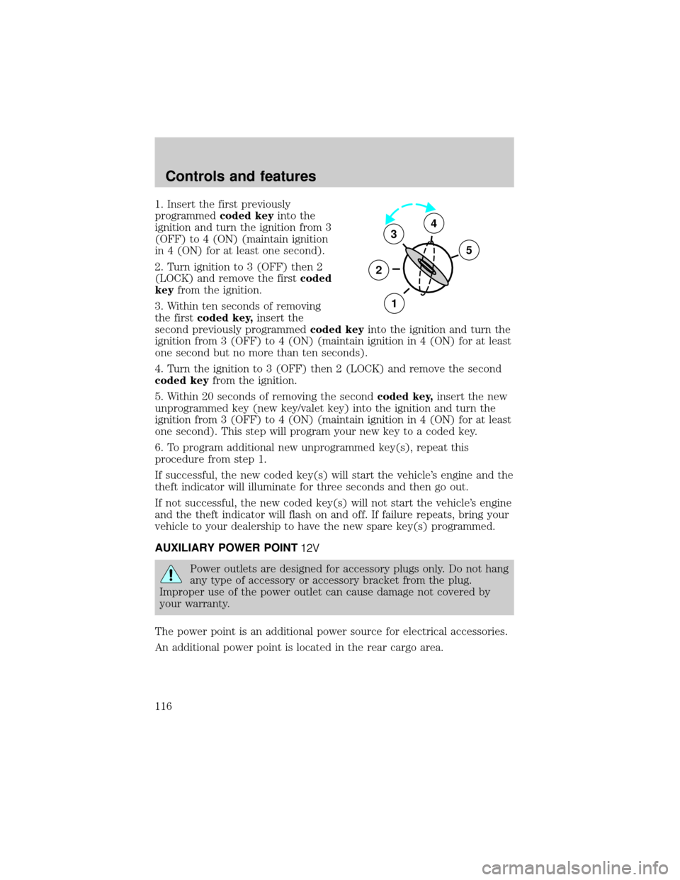
1. Insert the first previously
programmedcoded keyinto the
ignition and turn the ignition from 3
(OFF) to 4 (ON) (maintain ignition
in 4 (ON) for at least one second).
2. Turn ignition to 3 (OFF) then 2
(LOCK) and remove the firstcoded
keyfrom the ignition.
3. Within ten seconds of removing
the firstcoded key,insert the
second previously programmedcoded keyinto the ignition and turn the
ignition from 3 (OFF) to 4 (ON) (maintain ignition in 4 (ON) for at least
one second but no more than ten seconds).
4. Turn the ignition to 3 (OFF) then 2 (LOCK) and remove the second
coded keyfrom the ignition.
5. Within 20 seconds of removing the secondcoded key,insert the new
unprogrammed key (new key/valet key) into the ignition and turn the
ignition from 3 (OFF) to 4 (ON) (maintain ignition in 4 (ON) for at least
one second). This step will program your new key to a coded key.
6. To program additional new unprogrammed key(s), repeat this
procedure from step 1.
If successful, the new coded key(s) will start the vehicle's engine and the
theft indicator will illuminate for three seconds and then go out.
If not successful, the new coded key(s) will not start the vehicle's engine
and the theft indicator will flash on and off. If failure repeats, bring your
vehicle to your dealership to have the new spare key(s) programmed.
AUXILIARY POWER POINT
Power outlets are designed for accessory plugs only. Do not hang
any type of accessory or accessory bracket from the plug.
Improper use of the power outlet can cause damage not covered by
your warranty.
The power point is an additional power source for electrical accessories.
An additional power point is located in the rear cargo area.
3
2
1
5
4
Controls and features
116
Page 191 of 288
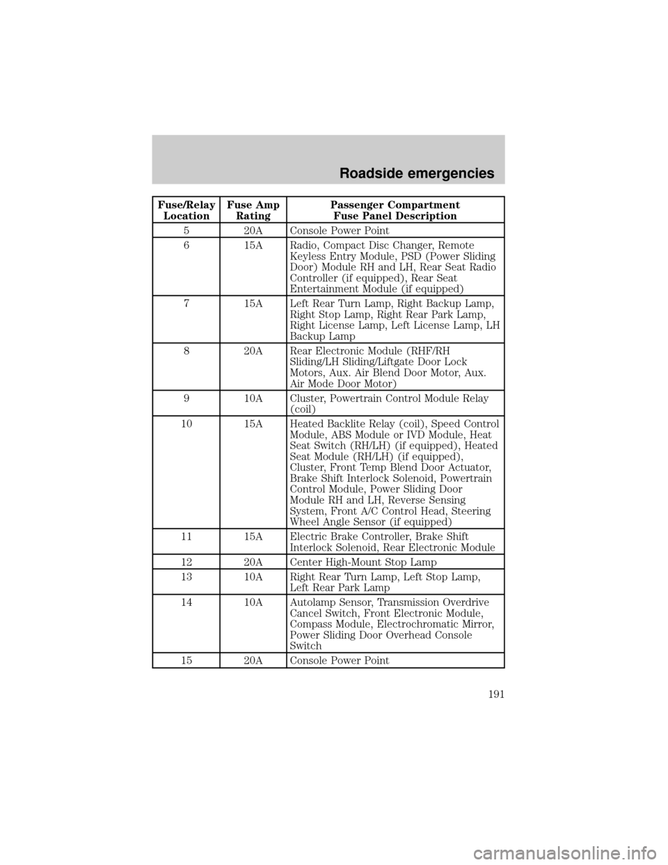
Fuse/Relay
LocationFuse Amp
RatingPassenger Compartment
Fuse Panel Description
5 20A Console Power Point
6 15A Radio, Compact Disc Changer, Remote
Keyless Entry Module, PSD (Power Sliding
Door) Module RH and LH, Rear Seat Radio
Controller (if equipped), Rear Seat
Entertainment Module (if equipped)
7 15A Left Rear Turn Lamp, Right Backup Lamp,
Right Stop Lamp, Right Rear Park Lamp,
Right License Lamp, Left License Lamp, LH
Backup Lamp
8 20A Rear Electronic Module (RHF/RH
Sliding/LH Sliding/Liftgate Door Lock
Motors, Aux. Air Blend Door Motor, Aux.
Air Mode Door Motor)
9 10A Cluster, Powertrain Control Module Relay
(coil)
10 15A Heated Backlite Relay (coil), Speed Control
Module, ABS Module or IVD Module, Heat
Seat Switch (RH/LH) (if equipped), Heated
Seat Module (RH/LH) (if equipped),
Cluster, Front Temp Blend Door Actuator,
Brake Shift Interlock Solenoid, Powertrain
Control Module, Power Sliding Door
Module RH and LH, Reverse Sensing
System, Front A/C Control Head, Steering
Wheel Angle Sensor (if equipped)
11 15A Electric Brake Controller, Brake Shift
Interlock Solenoid, Rear Electronic Module
12 20A Center High-Mount Stop Lamp
13 10A Right Rear Turn Lamp, Left Stop Lamp,
Left Rear Park Lamp
14 10A Autolamp Sensor, Transmission Overdrive
Cancel Switch, Front Electronic Module,
Compass Module, Electrochromatic Mirror,
Power Sliding Door Overhead Console
Switch
15 20A Console Power Point
Roadside emergencies
191
Page 192 of 288
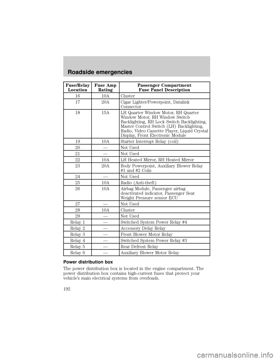
Fuse/Relay
LocationFuse Amp
RatingPassenger Compartment
Fuse Panel Description
16 10A Cluster
17 20A Cigar Lighter/Powerpoint, Datalink
Connector
18 15A LH Quarter Window Motor, RH Quarter
Window Motor, RH Window Switch
Backlighting, RH Lock Switch Backlighting,
Master Control Switch (LH) Backlighting,
Radio, Video Cassette Player, Liquid Crystal
Display, Front Electronic Module
19 10A Starter Interrupt Relay (coil)
20 Ð Not Used
21 Ð Not Used
22 10A LH Heated Mirror, RH Heated Mirror
23 20A Body Powerpoint, Auxiliary Blower Relay
#1 and #2 Coils
24 Ð Not Used
25 10A Radio (Anti-theft)
26 10A Airbag Module, Passenger airbag
deactivated indicator, Passenger Seat
Weight Pressure sensor ECU
27 Ð Not Used
28 10A Cluster
29 Ð Not Used
Relay 1 Ð Switched System Power Relay #4
Relay 2 Ð Accessory Delay Relay
Relay 3 Ð Front Blower Motor Relay
Relay 4 Ð Switched System Power Relay #3
Relay 5 Ð Rear Defrost Relay
Relay 6 Ð Auxiliary Blower Motor Relay
Power distribution box
The power distribution box is located in the engine compartment. The
power distribution box contains high-current fuses that protect your
vehicle's main electrical systems from overloads.
Roadside emergencies
192
Page 194 of 288
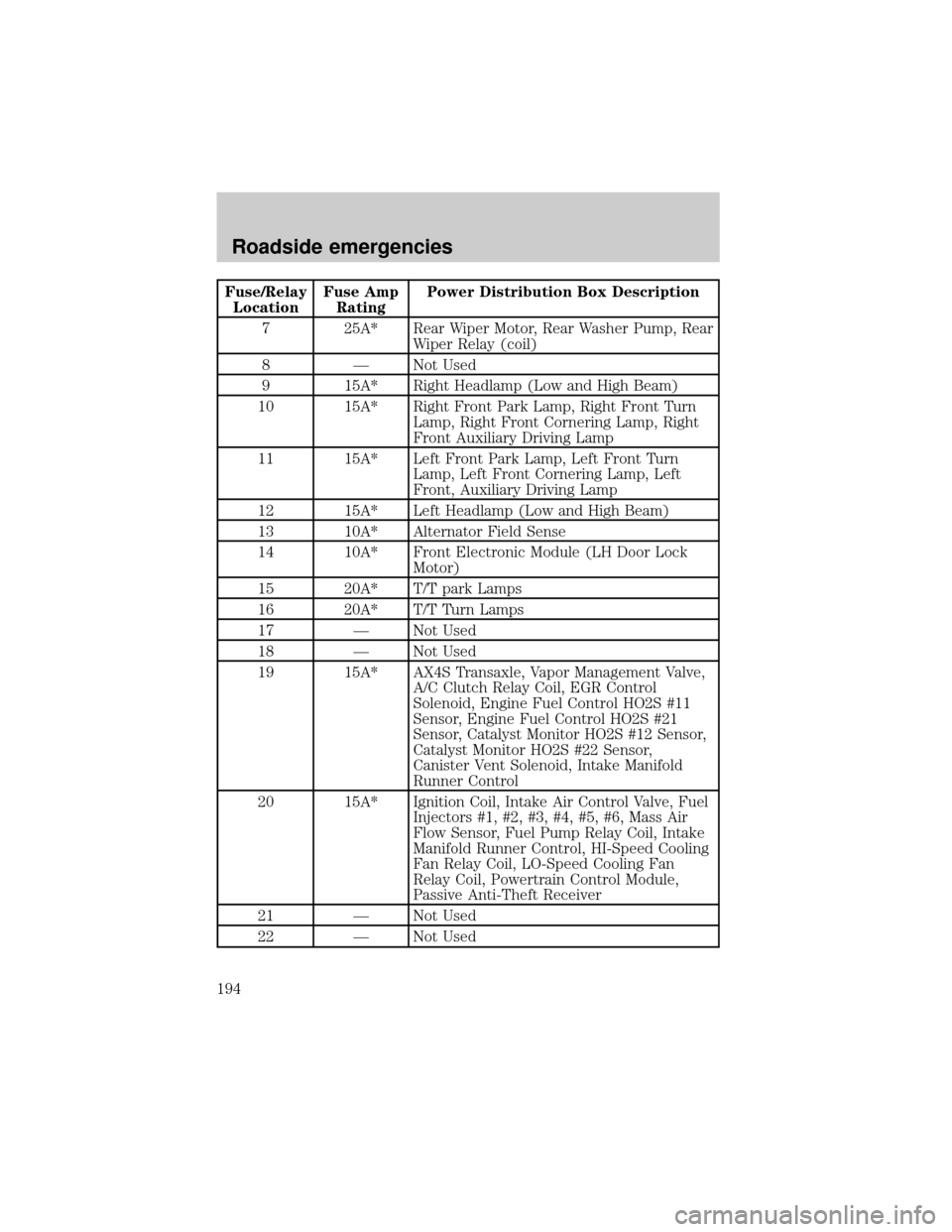
Fuse/Relay
LocationFuse Amp
RatingPower Distribution Box Description
7 25A* Rear Wiper Motor, Rear Washer Pump, Rear
Wiper Relay (coil)
8 Ð Not Used
9 15A* Right Headlamp (Low and High Beam)
10 15A* Right Front Park Lamp, Right Front Turn
Lamp, Right Front Cornering Lamp, Right
Front Auxiliary Driving Lamp
11 15A* Left Front Park Lamp, Left Front Turn
Lamp, Left Front Cornering Lamp, Left
Front, Auxiliary Driving Lamp
12 15A* Left Headlamp (Low and High Beam)
13 10A* Alternator Field Sense
14 10A* Front Electronic Module (LH Door Lock
Motor)
15 20A* T/T park Lamps
16 20A* T/T Turn Lamps
17 Ð Not Used
18 Ð Not Used
19 15A* AX4S Transaxle, Vapor Management Valve,
A/C Clutch Relay Coil, EGR Control
Solenoid, Engine Fuel Control HO2S #11
Sensor, Engine Fuel Control HO2S #21
Sensor, Catalyst Monitor HO2S #12 Sensor,
Catalyst Monitor HO2S #22 Sensor,
Canister Vent Solenoid, Intake Manifold
Runner Control
20 15A* Ignition Coil, Intake Air Control Valve, Fuel
Injectors #1, #2, #3, #4, #5, #6, Mass Air
Flow Sensor, Fuel Pump Relay Coil, Intake
Manifold Runner Control, HI-Speed Cooling
Fan Relay Coil, LO-Speed Cooling Fan
Relay Coil, Powertrain Control Module,
Passive Anti-Theft Receiver
21 Ð Not Used
22 Ð Not Used
Roadside emergencies
194
Page 195 of 288
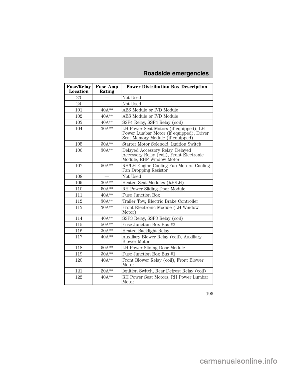
Fuse/Relay
LocationFuse Amp
RatingPower Distribution Box Description
23 Ð Not Used
24 Ð Not Used
101 40A** ABS Module or IVD Module
102 40A** ABS Module or IVD Module
103 40A** SSP4 Relay, SSP4 Relay (coil)
104 30A** LH Power Seat Motors (if equipped), LH
Power Lumbar Motor (if equipped), Driver
Seat Memory Module (if equipped)
105 30A** Starter Motor Solenoid, Ignition Switch
106 30A** Delayed Accessory Relay, Delayed
Accessory Relay (coil), Front Electronic
Module, RHF Window Motor
107 50A** RH/LH Engine Cooling Fan Motors, Cooling
Fan Dropping Resistor
108 Ð Not Used
109 30A** Heated Seat Modules (RH/LH)
110 50A** RH Power Sliding Door Module
111 40A** Fuse Junction Box
112 30A** Trailer Tow, Electric Brake Controller
113 30A** Front Electronic Module (LH Window
Motor)
114 40A** SSP3 Relay, SSP3 Relay (coil)
115 50A** Fuse Junction Box Bus #2
116 30A** Heated Backlight Relay
117 40A** Auxiliary Blower Relay (coil), Auxiliary
Blower Motor
118 50A** LH Power Sliding Door Module
119 30A** Fuse Junction Box Bus #1
120 40A** Front Blower Relay (coil), Front Blower
Motor
121 20A** Ignition Switch, Rear Defrost Relay (coil)
122 40A** RH Power Seat Motors, RH Power Lumbar
Motor
Roadside emergencies
195
Page 209 of 288
Do not start your engine with the air cleaner removed and do
not remove it while the engine is running.
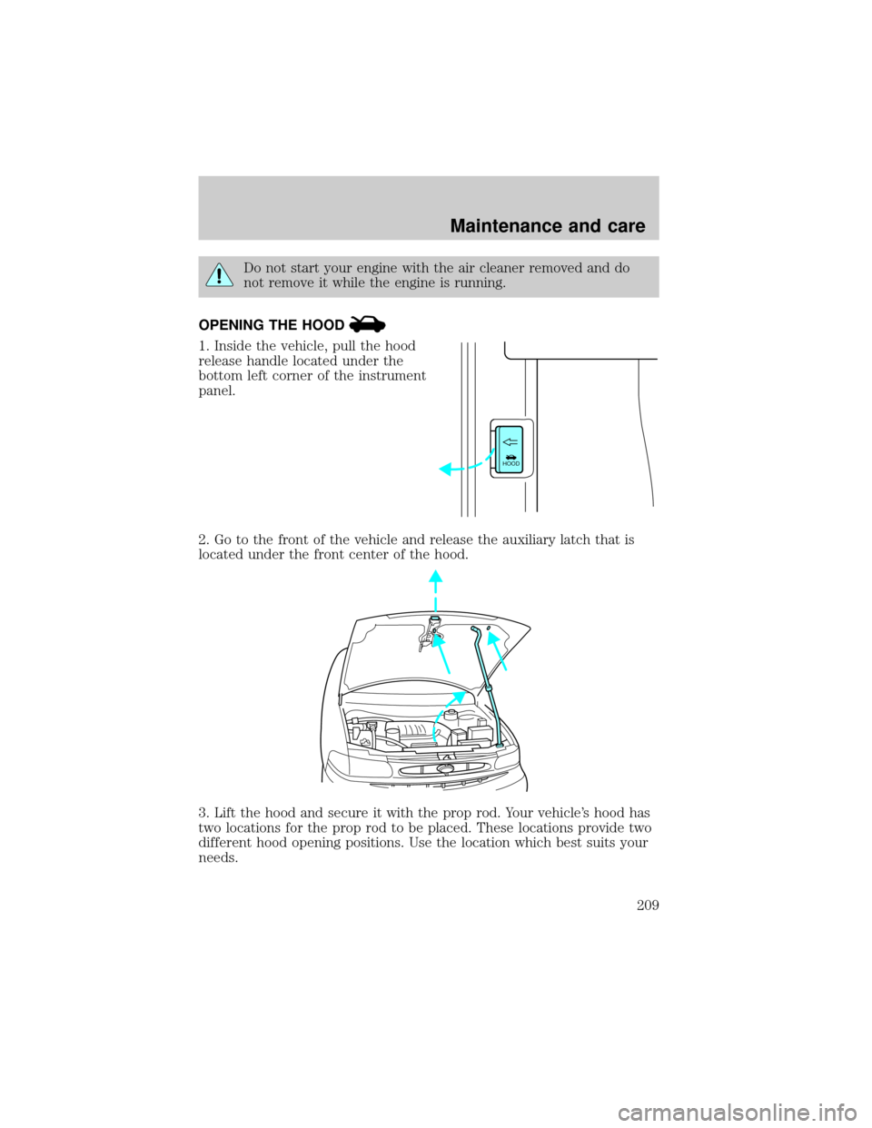
OPENING THE HOOD
1. Inside the vehicle, pull the hood
release handle located under the
bottom left corner of the instrument
panel.
2. Go to the front of the vehicle and release the auxiliary latch that is
located under the front center of the hood.
3. Lift the hood and secure it with the prop rod. Your vehicle's hood has
two locations for the prop rod to be placed. These locations provide two
different hood opening positions. Use the location which best suits your
needs.
HOOD
Maintenance and care
209
Page 245 of 288

Readiness for Inspection/Maintenance (I/M) testing
In some localities, it may be a legal requirement to pass an I/M test of
the on-board diagnostics system. If your ªCheck Engine/Service Engine
Soonº light is on, refer to the description in theWarning Lights and
Chimessection of theInstrumentationchapter. Your vehicle may not
pass the I/M test with the ªCheck Engine/Service Engine Soonº light on.
If the vehicle's powertrain system or its battery has just been serviced,
the on-board diagnostics system is reset to a ªnot ready for I/M testº
condition. To ready the on-board diagnostics system for I/M testing, a
minimum of 30 minutes of city and highway driving is necessary as
described below:
²First, at least 10 minutes of driving on an expressway or highway.
²Next, at least 20 minutes driving in stop-and-go, city-type traffic with
at least four idle periods.
Allow the vehicle to sit for at least eight hours without starting the
engine. Then, start the engine and complete the above driving cycle. The
engine must warm up to its normal operating temperature. Once started,
do not turn off the engine until the above driving cycle is complete.
BULBS
Replacing exterior bulbs
It is a good idea to check the operation of the following lights frequently:
²Headlamps
²Turn signals
²Cornering lamps (if equipped)
²Auxiliary parking lamps (if equipped)
²High-mount brakelamp
²Tail lamps
²Brakelamps
²Backup lamps
²License plate lamps
Do not remove lamp bulbs unless they will be replaced immediately. If a
bulb is removed for an extended period of time, contaminants may enter
the lamp housings and affect performance.
Maintenance and care
245
Page 249 of 288
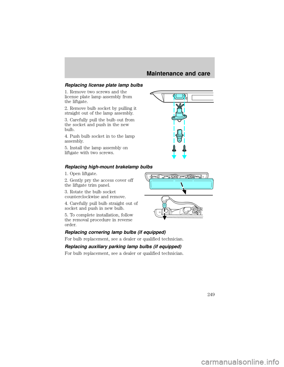
Replacing license plate lamp bulbs
1. Remove two screws and the
license plate lamp assembly from
the liftgate.
2. Remove bulb socket by pulling it
straight out of the lamp assembly.
3. Carefully pull the bulb out from
the socket and push in the new
bulb.
4. Push bulb socket in to the lamp
assembly.
5. Install the lamp assembly on
liftgate with two screws.
Replacing high-mount brakelamp bulbs
1. Open liftgate.
2. Gently pry the access cover off
the liftgate trim panel.
3. Rotate the bulb socket
counterclockwise and remove.
4. Carefully pull bulb straight out of
socket and push in new bulb.
5. To complete installation, follow
the removal procedure in reverse
order.
Replacing cornering lamp bulbs (if equipped)
For bulb replacement, see a dealer or qualified technician.
Replacing auxiliary parking lamp bulbs (if equipped)
For bulb replacement, see a dealer or qualified technician.
Maintenance and care
249