2001 FORD RANGER turn signal
[x] Cancel search: turn signalPage 8 of 272

C
012345
6
RPMx1000
ABS!
BRAKE
CHECK
ENGINE
CHECK
FUEL
CAP
EFH
H
HPRN D 2 1THEFT
SPEED
CONT
4WD
HIGH
4WD
LOW
O/D
OFFL
L
10MPH 205060
70
304080
90
km/h
0 0 0
10 100
1
20
10 0 0 0 0 0406080100
120
140
160
180
20
DOOR
AJAR
CHECK
GAGE
DIM
OFF
SET
ACC
COAST OFF ON
Headlamp control
(pg. 20)Instrument panel
dimmer control
(pg. 21)Instrument cluster
(pg. 10)
Speed control*
(pg. 65)
Hood release
(pg. 185) Driver air bag
(pg. 103)
Parking brake release
(pg. 129) Turn signal control
(pg. 64)
Wiper/washer control
(pg. 71)
Instrumentation
8
Page 13 of 272

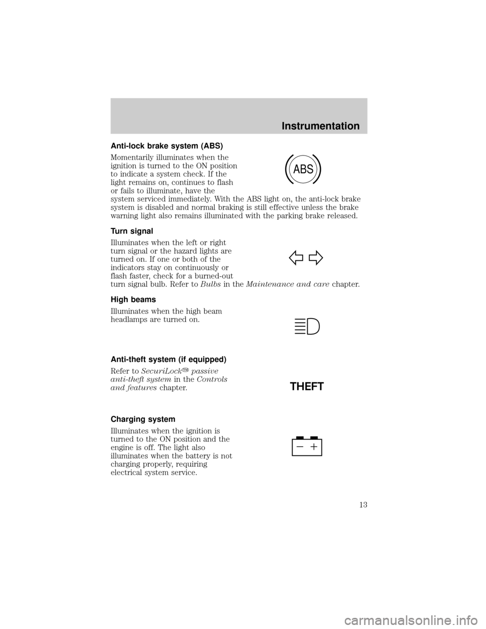
Anti-lock brake system (ABS)
Momentarily illuminates when the
ignition is turned to the ON position
to indicate a system check. If the
light remains on, continues to flash
or fails to illuminate, have the
system serviced immediately. With the ABS light on, the anti-lock brake
system is disabled and normal braking is still effective unless the brake
warning light also remains illuminated with the parking brake released.
Turn signal
Illuminates when the left or right
turn signal or the hazard lights are
turned on. If one or both of the
indicators stay on continuously or
flash faster, check for a burned-out
turn signal bulb. Refer toBulbsin theMaintenance and carechapter.
High beams
Illuminates when the high beam
headlamps are turned on.
Anti-theft system (if equipped)
Refer toSecuriLockypassive
anti-theft systemin theControls
and featureschapter.
Charging system
Illuminates when the ignition is
turned to the ON position and the
engine is off. The light also
illuminates when the battery is not
charging properly, requiring
electrical system service.
ABS
THEFT
Instrumentation
13
Page 63 of 272

Radio frequency information
The Federal Communications Commission (FCC) and the Canadian Radio
and Telecommunications Commission(CRTC) establish the frequencies
AM and FM stations may use for their broadcasts. Allowable frequencies
are:
AM 530, 540±1600, 1610 kHz
FM 87.7, 87.9±107.7, 107.9 MHz
Not all frequencies are used in a given area.
Radio reception factors
Three factors can affect radio reception:
²Distance/strength.The further an FM signal travels, the weaker it is.
The listenable range of the average FM station is approximately 40 km
(24 miles). This range can be affected by ªsignal modulation.º Signal
modulation is a process radio stations use to increase their
strength/volume relative to other stations.
²Terrain.Hills, mountains and tall buildings between your vehicle's
antenna and the radio station signal can cause FM reception problems.
Static can be caused on AM stations by power lines, electric fences,
traffic lights and thunderstorms. Moving away from an interfering
structure (out of its ªshadowº) returns your reception to normal.
²Station overload.Weak signals are sometimes captured by stronger
signals when you pass a broadcast tower. A stronger signal may
temporarily overtake a weaker signal and play while the weak station
frequency is displayed.
The audio system automatically switches to single channel reception if it
will improve the reception of a station normally received in stereo.
Audio system warranties and service
Refer to theWarranty Guidefor audio system warranty information.
If service is necessary, see your dealer or a qualified technician.
Controls and features
63
Page 64 of 272

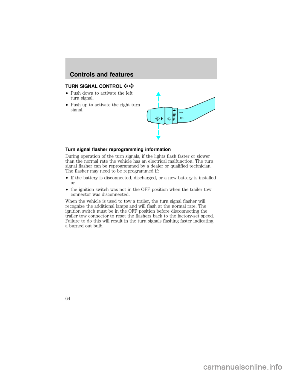
TURN SIGNAL CONTROL
²Push down to activate the left
turn signal.
²Push up to activate the right turn
signal.
Turn signal flasher reprogramming information
During operation of the turn signals, if the lights flash faster or slower
than the normal rate the vehicle has an electrical malfunction. The turn
signal flasher can be reprogrammed by a dealer or qualified technician.
The flasher may need to be reprogrammed if:
²If the battery is disconnected, discharged, or a new battery is installed
or
²the ignition switch was not in the OFF position when the trailer tow
connector was disconnected.
When the vehicle is used to tow a trailer, the turn signal flasher will
recognize the additional lamps and will flash at the normal rate. The
ignition switch must be in the OFF position before disconnecting the
trailer tow connector to reset the flashers back to the factory-set speed.
Failure to do this will result in the turn signals flashing faster indicating
a burned out bulb.
Controls and features
64
Page 155 of 272

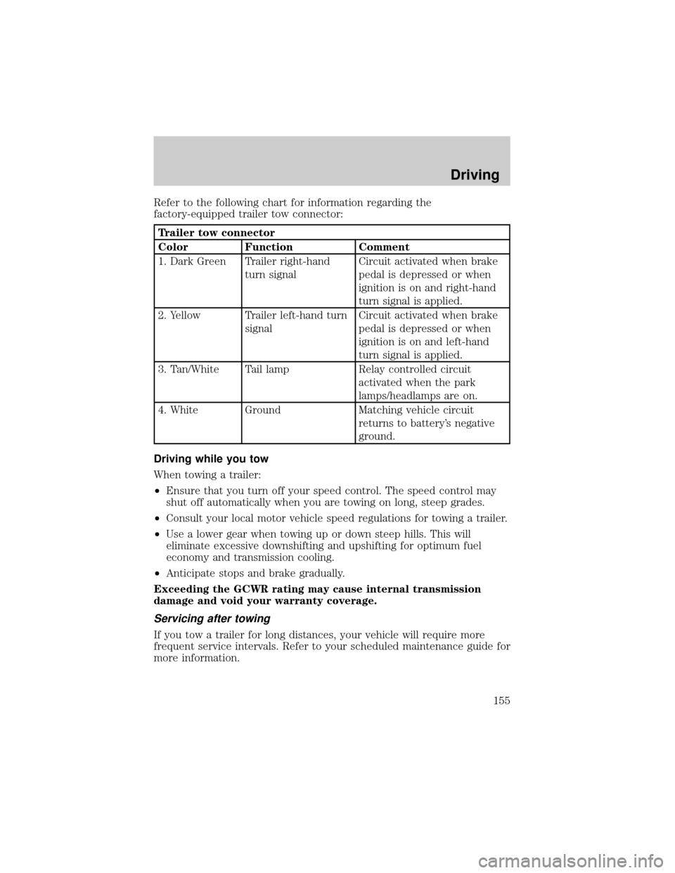
Refer to the following chart for information regarding the
factory-equipped trailer tow connector:
Trailer tow connector
Color Function Comment
1. Dark Green Trailer right-hand
turn signalCircuit activated when brake
pedal is depressed or when
ignition is on and right-hand
turn signal is applied.
2. Yellow Trailer left-hand turn
signalCircuit activated when brake
pedal is depressed or when
ignition is on and left-hand
turn signal is applied.
3. Tan/White Tail lamp Relay controlled circuit
activated when the park
lamps/headlamps are on.
4. White Ground Matching vehicle circuit
returns to battery's negative
ground.
Driving while you tow
When towing a trailer:
²Ensure that you turn off your speed control. The speed control may
shut off automatically when you are towing on long, steep grades.
²Consult your local motor vehicle speed regulations for towing a trailer.
²Use a lower gear when towing up or down steep hills. This will
eliminate excessive downshifting and upshifting for optimum fuel
economy and transmission cooling.
²Anticipate stops and brake gradually.
Exceeding the GCWR rating may cause internal transmission
damage and void your warranty coverage.
Servicing after towing
If you tow a trailer for long distances, your vehicle will require more
frequent service intervals. Refer to your scheduled maintenance guide for
more information.
Driving
155
Page 163 of 272

The fuses are coded as follows:
Fuse/Relay
LocationFuse Amp
RatingPassenger Compartment Fuse
Panel Description
1 5A Power Mirror Switch
2 10A Daytime Running Lights (DRL),
Back-up Lamps, Transmission,
Passenger Air Bag Deactivation
Switch, Blower Motor Relay
3 7.5A Right Stop/Turn Trailer Tow
Connector
4 Ð Not Used
5 15A 4x4 Control Module
6 Ð Not Used
7 7.5A Left Stop/Turn Trailer Tow
Connector
8 Ð Not Used
9 7.5A Brake Pedal Position Switch
10 7.5A Speed Control Servo/Amplifier
Assembly, Generic Electronic
Module (GEM), Shift Lock
Actuator, Turn Signals
11 7.5A Instrument Cluster, 4x4, Main
Light Switch, Truck Central
Security Module (TCSM)
12 Ð Not Used
13 20A Brake Pedal Position Switch
14 10A or Not Used 10A: If equipped with Anti-Lock
Brake System (ABS) Control
Module
15 Ð Not Used
16 30A Windshield Wiper Motor, Wiper
Hi-Lo Relay, Wiper Run/Park
Relay
Roadside emergencies
163
Page 227 of 272

BULBS
Replacing exterior bulbs
Check the operation of the following lamps frequently:
²Headlamps
²Foglamps
²High-mount brakelamp
²Brakelamps
²Turn signals
²License plate lamp
²Tail lamps
²Back-up lamps
Do not remove lamp bulbs unless they can be replaced immediately with
new ones. If a bulb is removed for an extended period of time,
contaminants may enter the lamp housings and affect lamp performance.
Replacing headlamp bulbs
To remove the headlamp bulb:
1. Make sure headlamp switch is in
OFF position, then open the hood.
2. Remove two screws and cover (if
equipped).
3. At the back of the headlamp, pry
up the two retainer pins to release
the headlamp assembly from the
vehicle and pull headlamp forward.
4. Disconnect the electrical
connector from the bulb by pulling
rearward.
Maintenance and care
227
Page 266 of 272

H
Hazard flashers .........................159
Headlamps ...................................20
aiming ......................................233
bulb specifications ..................232
daytime running lights .............20
flash to pass ..............................21
high beam ...........................13, 21
replacing bulbs .......................227
turning on and off ....................20
warning chime ..........................15
Heating ........................................22
heater only system ...................22
Hood ..........................................185
I
Ignition .........................65, 245±246
Infant seats
(see Safety seats) .....................114
Inspection/maintenance (I/M)
testing ........................................226
Instrument panel
cleaning ...................................238
cluster ................................10, 238
lighting up panel and
interior .......................................21
location of components ............10
J
Jack ............................................171
positioning .......................171, 175
storage .....................171±173, 175
Jump-starting your vehicle ......178K
Keys .......................................85±87
key in ignition chime ...............15
positions of the ignition ...........65
L
Lamps
bulb replacement
specifications chart ................232
cargo lamps ...............................21
daytime running light ...............20
fog lamps ...................................20
headlamps .................................20
headlamps, flash to pass ..........21
instrument panel, dimming .....21
interior lamps ...................71, 233
replacing bulbs .......227, 229±232
Lane change indicator (see
Turn signal) .................................64
Lights, warning and indicator ....10
air bag ........................................12
anti-lock brakes (ABS) ....13, 129
anti-theft ...................................13
brake ..........................................12
charging system ........................13
check coolant ............................12
check engine .............................10
cruise indicator .........................15
door ajar ....................................14
fuel cap light .............................11
high beam .................................13
overdrive off ..............................14
safety belt .................................12
speed control ............................69
turn signal indicator .................13
Load limits .................................144
GAWR ......................................144
GVWR ......................................144
Index
266