Page 5 of 240
Vehicle Symbol Glossary
Child Safety Door
Lock/Unlock
Interior Luggage
Compartment Release
Symbol
Panic AlarmEngine Oil
Engine CoolantEngine Coolant
Temperature
Do Not Open When HotBattery
Avoid Smoking, Flames,
or SparksBattery Acid
Explosive GasFan Warning
Power Steering FluidMaintain Correct Fluid
LevelMAX
MIN
Emission SystemEngine Air Filter
Passenger Compartment
Air FilterJack
Check fuel cap
Introduction
5
Page 12 of 240
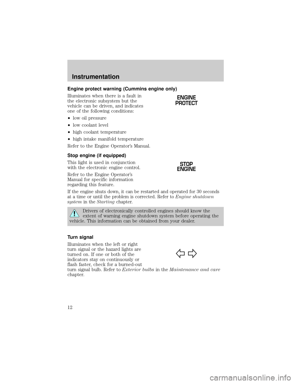
Engine protect warning (Cummins engine only)
Illuminates when there is a fault in
the electronic subsystem but the
vehicle can be driven, and indicates
one of the following conditions:
²low oil pressure
²low coolant level
²high coolant temperature
²high intake manifold temperature
Refer to the Engine Operator's Manual.
Stop engine (if equipped)
This light is used in conjunction
with the electronic engine control.
Refer to the Engine Operator's
Manual for specific information
regarding this feature.
If the engine shuts down, it can be restarted and operated for 30 seconds
at a time or until the problem is corrected. Refer toEngine shutdown
systemin theStartingchapter.
Drivers of electronically controlled engines should know the
extent of warning engine shutdown system before operating the
vehicle. This information can be obtained from your dealer.
Turn signal
Illuminates when the left or right
turn signal or the hazard lights are
turned on. If one or both of the
indicators stay on continuously or
flash faster, check for a burned-out
turn signal bulb. Refer toExterior bulbsin theMaintenance and care
chapter.
ENGINE
PROTECT
STOP
ENGINE
Instrumentation
12
Page 20 of 240
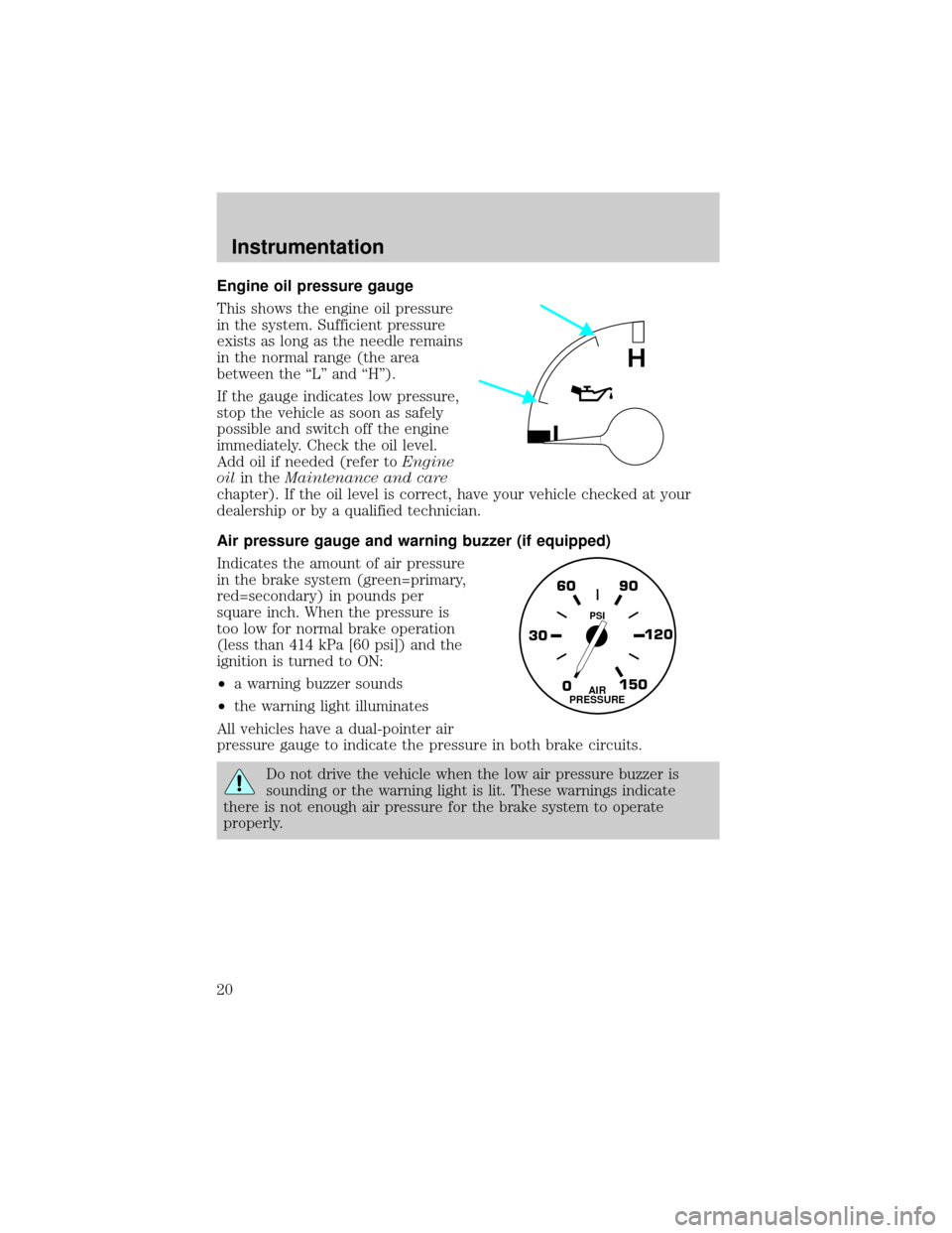
Engine oil pressure gauge
This shows the engine oil pressure
in the system. Sufficient pressure
exists as long as the needle remains
in the normal range (the area
between the ªLº and ªHº).
If the gauge indicates low pressure,
stop the vehicle as soon as safely
possible and switch off the engine
immediately. Check the oil level.
Add oil if needed (refer toEngine
oilin theMaintenance and care
chapter). If the oil level is correct, have your vehicle checked at your
dealership or by a qualified technician.
Air pressure gauge and warning buzzer (if equipped)
Indicates the amount of air pressure
in the brake system (green=primary,
red=secondary) in pounds per
square inch. When the pressure is
too low for normal brake operation
(less than 414 kPa [60 psi]) and the
ignition is turned to ON:
²a warning buzzer sounds
²the warning light illuminates
All vehicles have a dual-pointer air
pressure gauge to indicate the pressure in both brake circuits.
Do not drive the vehicle when the low air pressure buzzer is
sounding or the warning light is lit. These warnings indicate
there is not enough air pressure for the brake system to operate
properly.
L
H
0 30120 90 60
150AIR
PRESSURE
PSI
Instrumentation
20
Page 104 of 240
OPERATING THE ENGINE
Do not operate the engine at full throttle below peak torque engine
speed (RPM) for more than one minute at a time (peak torque RPM
varies from 1200-1500 RPM depending on engine rated speed).
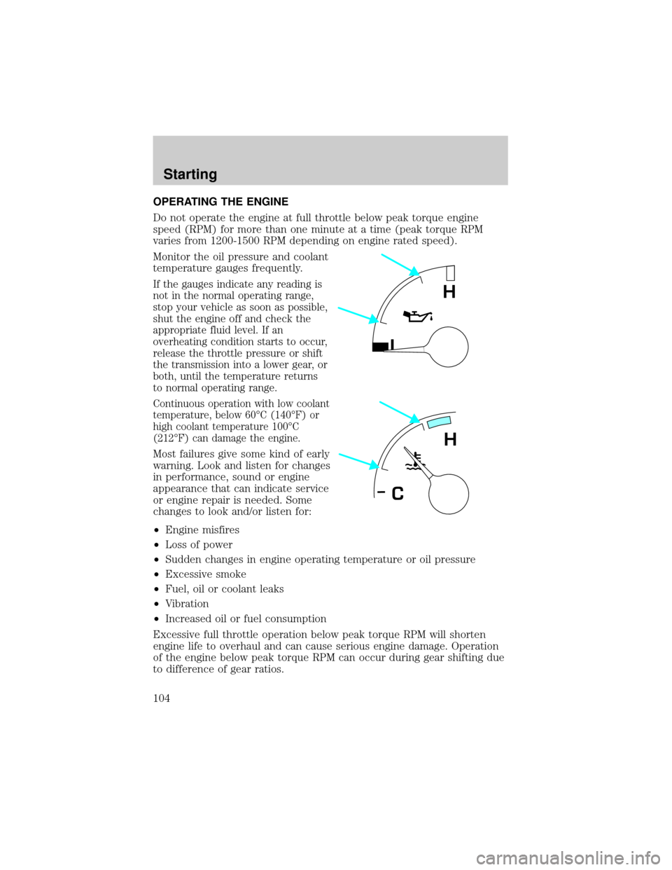
Monitor the oil pressure and coolant
temperature gauges frequently.
If the gauges indicate any reading is
not in the normal operating range,
stop your vehicle as soon as possible,
shut the engine off and check the
appropriate fluid level. If an
overheating condition starts to occur,
release the throttle pressure or shift
the transmission into a lower gear, or
both, until the temperature returns
to normal operating range.
Continuous operation with low coolant
temperature, below 60ÉC (140ÉF) or
high coolant temperature 100ÉC
(212ÉF) can damage the engine.
Most failures give some kind of early
warning. Look and listen for changes
in performance, sound or engine
appearance that can indicate service
or engine repair is needed. Some
changes to look and/or listen for:
²Engine misfires
²Loss of power
²Sudden changes in engine operating temperature or oil pressure
²Excessive smoke
²Fuel, oil or coolant leaks
²Vibration
²Increased oil or fuel consumption
Excessive full throttle operation below peak torque RPM will shorten
engine life to overhaul and can cause serious engine damage. Operation
of the engine below peak torque RPM can occur during gear shifting due
to difference of gear ratios.
L
H
H
C
Starting
104
Page 159 of 240
4. Tilt the hood forward until
stopped by the retaining cables.
To lower the hood:
1. Push the hood rearward at the top center of the hood above the grille
until closed.
2. Engage the latch on each fender.
3. Push down on the bottom of each latch until locked.
To avoid the possibility of personal injury, never stand beneath
the hood when it is being raised or lowered.
ENGINE OIL
Checking engine oil levelÐCummins B and Caterpillar 3126 B engines
Refer to the appropriate engine operator's manual for information on the
engine oil.
Maintenance and care
159
Page 160 of 240
Checking engine oil levelÐ7.3L Power Stroke engine
Refer to the Scheduled Maintenance Guide for the appropriate intervals
for checking the engine oil.
Check the engine oil level consistently and accurately. The following
procedure is recommended:
1. Start the engine and let it run until it reaches normal operating
temperature (the engine coolant temperature gauge indicator will be
near the center of the normal area between H and C).
2. Park the vehicle on level ground.
3. Set the parking brake and shift into N (Neutral) (automatic
transmission) or 1 (First) (manual transmission).
4. Turn off the engine and wait a few minutes for the oil to drain
completely into the oil pan.
5. Open the hood. Protect yourself from engine heat.
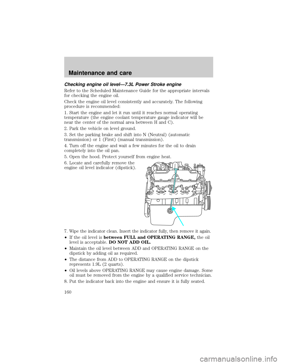
6. Locate and carefully remove the
engine oil level indicator (dipstick).
7. Wipe the indicator clean. Insert the indicator fully, then remove it again.
²If the oil level isbetween FULL and OPERATING RANGE,the oil
level is acceptable.DO NOT ADD OIL.
²Maintain the oil level between ADD and OPERATING RANGE on the
dipstick by adding oil as required.
²The distance from ADD to OPERATING RANGE on the dipstick
represents 1.9L (2 quarts).
²Oil levels above OPERATING RANGE may cause engine damage. Some
oil must be removed from the engine by a qualified service technician.
8. Put the indicator back into the engine and ensure it is fully seated.
Maintenance and care
160
Page 179 of 240
SERVICING YOUR WHEELS AND TIRES
Wheel assembly
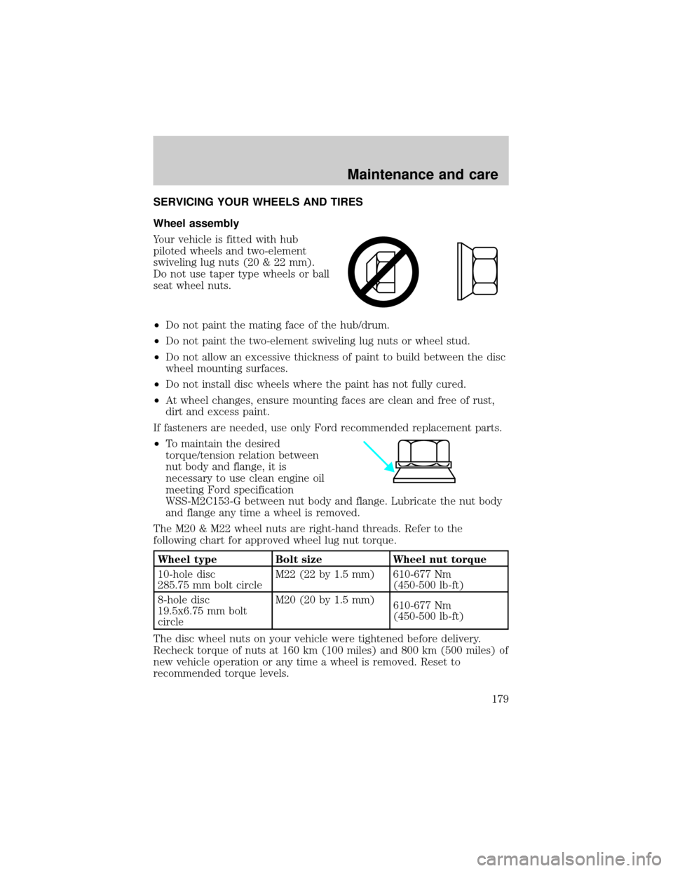
Your vehicle is fitted with hub
piloted wheels and two-element
swiveling lug nuts (20 & 22 mm).
Do not use taper type wheels or ball
seat wheel nuts.
²Do not paint the mating face of the hub/drum.
²Do not paint the two-element swiveling lug nuts or wheel stud.
²Do not allow an excessive thickness of paint to build between the disc
wheel mounting surfaces.
²Do not install disc wheels where the paint has not fully cured.
²At wheel changes, ensure mounting faces are clean and free of rust,
dirt and excess paint.
If fasteners are needed, use only Ford recommended replacement parts.
²To maintain the desired
torque/tension relation between
nut body and flange, it is
necessary to use clean engine oil
meeting Ford specification
WSS-M2C153-G between nut body and flange. Lubricate the nut body
and flange any time a wheel is removed.
The M20 & M22 wheel nuts are right-hand threads. Refer to the
following chart for approved wheel lug nut torque.
Wheel type Bolt size Wheel nut torque
10-hole disc
285.75 mm bolt circleM22 (22 by 1.5 mm) 610-677 Nm
(450-500 lb-ft)
8-hole disc
19.5x6.75 mm bolt
circleM20 (20 by 1.5 mm)
610-677 Nm
(450-500 lb-ft)
The disc wheel nuts on your vehicle were tightened before delivery.
Recheck torque of nuts at 160 km (100 miles) and 800 km (500 miles) of
new vehicle operation or any time a wheel is removed. Reset to
recommended torque levels.
Maintenance and care
179
Page 182 of 240
Tire inflation pressure must not exceed the recommendations of
the axle, tire and/or wheel rim manufacturer for the specific
load, speed and application. The inflation pressures on the tire sidewall
do not take the wheel rim capabilities into consideration.
Never use a rim of different manufacture or any different size or
type than original rims.
Try to replace tires in pairs on the same axle shaft. Tires larger or
smaller than originally installed may affect the accuracy of the
speedometer. Consult your dealer about the need to change the switch
setting on the back of the speedometer.
Front wheel alignment
If abnormal tire wear or ride and handling characteristics such as vehicle
lead or wander are experienced with properly inflated tires, the front
end alignment should be checked.
Wheel bearing care
Front and rear wheel bearings are adjustable to correct for bearing and
spindle wear. Long bearing life depends upon proper adjustment and
correct lubrication. If bearings are adjusted too tightly (preloaded) they
will overheat and wear rapidly. Loose adjustment will cause pounding
and will contribute to uneven tire wear, steering difficulties and
inefficient brake operation.
Refer to the Ford Service Manual applicable to your vehicle for proper
tightening procedures and torque specifications.
Periodically check the oil level on oil filled front bearing hubs. If
necessary, add oil through the filler plug so the oil level is between the
ADD and FULL marks indicated on the hub. Do not overfill. Overfilling
can result in oil on brake linings.
Refer to your Scheduled Maintenance Guide for fluid level checks and
change intervals for the front hubs.
Your front hubs may be filled with an optional synthetic fluid which
allows use of the extended service intervals. A green colored filler plug
identifies use of the synthetic fluid.
Maintenance and care
182