Page 130 of 240
To go forward
With the engine idling, depress the
clutch pedal and shift into 1 (First).
Engage the clutch while pressing
the accelerator to start forward.
Operate the clutch and upshift as
required by driving conditions.
To go backward
Reverse is obtained by putting the
gearshift lever in R (Reverse) and
engaging the clutch while pressing
lightly on the accelerator.
Removing key from ignition
²Turn the ignition key to position 2.
²Push the release lever forward
and rotate the key towards you
and remove.
2 4 6
3 5 7
1 R
2 4 6
3 5 7
1 R
Driving
130
Page 131 of 240

Power-take off operation (PTO) with a manual transmission
Transmission-mounted power take-off units are available for local
installation on Ford vehicles. See your Body Builder's Layout Book for
restrictions on use and installation of power take-off units.
To engage the PTO unit, stop the vehicle and place the transmission
control in neutral. Depress the clutch and allow the gears to stop
rotating, then engage the PTO unit. The PTO can also be selected with
the transmission in gear as long as the clutch is depressed.
When operating the PTO unit with the vehicle stationary, first set the
parking brake (chock the wheels if the vehicle is on a hill or other
unlevel surface).
DRIVING WITH AN AUTOMATIC TRANSMISSION, IF EQUIPPED
Allison automatic transmission
Do not allow your vehicle to coast in N (Neutral). Transmission
braking is not available in N (Neutral). Allowing the vehicle to
coast in N (Neutral) could result in loss of vehicle control and severe
transmission damage.
The Allison automatic transmissions are a torque converter type, full
power shifting and fully automatic. They also have the added flexibility
of manually selecting and holding in the lower drive ranges which permit
the drive selection of the most suitable gear range to match varying road
and load conditions. To prevent destructive overspeeding of the engine,
the hold feature is not infinite, resulting in upshifts from the hold range
to the next higher range at some speed above the no-load governed
speed of the engine.
Allison AT-545
These transmissions have no P (Park) position. Before leaving
the driver's seat, always shift into N (Neutral) and set the
parking brake. Shut off the engine and remove your ignition key.
Always use wheel chocks for hilly or off-road parking. Unexpected and
possibly sudden vehicle movement may occur if these precautions are
not taken.
This transmission provides four forward speeds and one reverse range.
Driving
131
Page 139 of 240

PTO operation with vehicle stationary
To operate the power take-off, stop the vehicle, idle the engine and set
the parking brake. Make sure the gear selector is in any forward drive
range, then engage the PTO. After the PTO is engaged for stationary
vehicle operation, move the range selector to N (Neutral). Increase the
engine speed until the desired power take-off operation speed is
obtained. To disengage the PTO after operation with the vehicle
standing, release the throttle, allow the drive equipment to come to a
stop, and then disengage the PTO.
When the PTO is operated with the vehicle stationary, the
transmission must be placed in N (Neutral). If the transmission
is not in N (Neutral) and is equipped with a remote throttle control, an
increase in engine speed can overpower the parking brake and cause
the vehicle to move, possibly resulting in personal and/or property
damage.
PTO operation while vehicle is moving
After the PTO is engaged for driven vehicle operation, shift to the desired
range and drive the vehicle. The speed of the PTO, during this period of
operation, will always maintain direct relation to vehicle speed. PTO speed
will decrease in relation to vehicle (transmission output) speed as shifts to
a higher gear occur. When operating the PTO while the vehicle is moving,
the PTO may be disengaged whenever it is no longer required. When there
is no load on the PTO gear, it can be pulled out of engagement.
Power take-off (PTO) operation with an Allison automatic
transmission (MD applications)
The PTO drive gear is engine driven and provides direct engine power. The
PTO can be operated when the vehicle is either stationary or moving.
The PTO gear is in constant mesh with the drive gear in the torque
converter housing. A friction clutch or constant drive is used to transmit
power to the PTO.
Power take-off (PTO) operation on vehicles equipped with a
Caterpillar 3126E engine
If your vehicle is equipped with a Caterpillar 3126E engine, the PTO will
only operate if the vehicle is in Neutral. This feature can be overriden by
a special service tool; see your dealer or service representative for more
information.
Driving
139
Page 145 of 240
Passenger compartment fuse panel
The fuse panel is located below and to the left of the steering wheel by
the brake pedal. Remove the panel cover to access the fuses.
To remove a fuse use the fuse puller tool provided on the fuse panel cover.
The fuses are coded as follows.
Fuse/Relay
LocationFuse Amp
RatingPassenger Compartment Fuse
Panel Description
1 20A Horn
2 15A Turn/Hazard Lamps
3 20A Cigar Lighter
4 10A Diagnostic Connectors
5 15A Back-Up Lamps, DRL Relays,
Blend Door Actuator, Heated Seat
Module (SuperCrewzer only),
On/Off Fan Clutch (SuperCrewzer
only), Warning Chime Module
(SuperCrewzer only)
Relay #1
Relay #2
Relay #3
Horn
Relay #4
Relay #5 One Touch
Down Interior
Lamps#1
#12#22
#2
#3
#4
#5
#6
#7
#8
#9
#10
#11#13
#23
#14
#15
#16
#17#24
#25
#26
#27
#18
#28
#19
#29
#20
#21#30
#31
Roadside emergencies
145
Page 147 of 240
Fuse/Relay
LocationFuse Amp
RatingPassenger Compartment Fuse
Panel Description
23 10A Electronic Flasher
24 15A Vacuum Pump, Air Dryer, ABS,
Fuel Heater Relay
25 10A Blower Motor Relay
26 10A Right Low Beam Headlamp
27 Ð Not Used
28 10A Left Low Beam Headlamp
29 10A Cluster, GEM, 7.3L Power Stroke
PCM (clutch switch input), APCM
(7.3L Power Stroke only),
Overhead Console (SuperCrewzer
only), Keyless Entry Module
(SuperCrewzer only), Traxx
(Fuel) Module (SuperCrewzer
only)
30 30A 7.3L Power Stroke PCM Diode,
7.3L Power Stroke Fuel Heater
31 15A Allison MD Transmission, Neutral
Start Relay and PCM (7.3L Power
Stroke only)
Relay 1 Ð Interior Lamps
Relay 2 Ð Not Used
Relay 3 Ð Horn
Relay 4 Ð One Touch Down
Relay 5 Ð Not Used
Roadside emergencies
147
Page 164 of 240

CLUTCH (IF EQUIPPED)ÐLINKAGE LUBRICATION
Lubricate the clutch linkage using the following procedure. Refer to the
Scheduled Maintenance Guide for the service interval schedules.
Use a grease which meets Ford specifications. Refer toCapacities and
specifications.
1. Set the parking brake, shift into 1 (First) and turn the engine off.
2. Remove the inspection cover from the clutch housing.
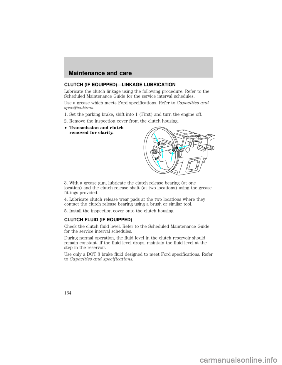
²Transmission and clutch
removed for clarity.
3. With a grease gun, lubricate the clutch release bearing (at one
location) and the clutch release shaft (at two locations) using the grease
fittings provided.
4. Lubricate clutch release wear pads at the two locations where they
contact the clutch release bearing using a brush or similar tool.
5. Install the inspection cover onto the clutch housing.
CLUTCH FLUID (IF EQUIPPED)
Check the clutch fluid level. Refer to the Scheduled Maintenance Guide
for the service interval schedules.
During normal operation, the fluid level in the clutch reservoir should
remain constant. If the fluid level drops, maintain the fluid level at the
step in the reservoir.
Use only a DOT 3 brake fluid designed to meet Ford specifications. Refer
toCapacities and specifications.
Maintenance and care
164
Page 168 of 240

Adding and replacing engine coolant-Caterpillar 3126 B engine
Refer to the engine operator's manual for additional engine cooling
system information.
FAN CLUTCHES
Your vehicle's cooling system is equipped with a viscous variable speed
fan clutch.
²The fan clutch helps control cooling, increase performance, improve
fuel economy and reduce noise.
²The fan clutch is controlled by bimetallic spring sensors. Do not
tamper with these sensors as this may change their calibration or keep
the fan clutch from operating at all.
Stay clear of the fan/fan area while the engine is running or
possible personal injury may occur.
CHECKING AND ADDING POWER STEERING FLUID
Checking power steering fluid level
Check the power steering fluid level using the following procedure. Refer
to the scheduled maintenance guide for the recommended service
intervals. If adding fluid is necessary, use only MERCONtAT F.
1. Set the parking brake, shift into N
(Neutral) (automatic transmission)
or 1 (First) (manual transmission)
and turn the engine off.
2. Open the hood.
3. Clean the top of the power
steering fluid reservoir.
4. Remove the dipstick from the
reservoir and wipe the dipstick clean.
Maintenance and care
168
Page 201 of 240
REAR AXLE REFILL CAPACITIES
Make and model Approximate capacity
Rockwell RS-17-144116.6L (35 pints)
Rockwell RS-17-1451, 216.6L (35 pints)
Rockwell RS-21-1451, 216.6L (35 pints)
Rockwell RS-23-1601, 218.9L (40 pints)
1Quantities listed are approximate. Fill axle until the lubricant level is at
bottom of filler hole, with vehicle on level ground.
2If hubs have been removed, add an additional 0.75 liter (1.6 pints) of
axle lubricant. Add lubricant through the axle vent.
FUEL TANK CAPACITIES
Type Approximate capacity
Single tank 246.09L (65 gallons)
Dual tank 492.18L (130 gallons)
LUBRICANT SPECIFICATIONS
Item Ford Part NameFord Part
NumberFord
Specification
Brake and clutch
fluid
(if equipped)High Performance
DOT 3 Motor
Vehicle Brake FluidC6AZ-19542-AB ESA-M6C25-A
and DOT 3
Body hinges,
hood hinges and
latches.Multi-Purpose
GreaseD0AZ-19584-AA
or
F5AZ-19G209-AAESB-M1C93-B
or
ESR-M1C159-A
Lock cylinders Penetrating
LubricantXL-1 N/A
Capacities and specifications
201