Page 6 of 240

ENTERING, EXITING AND/OR CLIMBING ON THIS VEHICLE
You must be careful and deliberate to minimize the possibility of personal
injury from a slip and fall when entering, exiting and/or climbing on this
vehicle. Always use the steps and assist handles before climbing. Do not
skip any steps or assist handles. Use three point contact at all times with
at least two feet and one hand or two hands and one foot firmly placed
during all phases of entering, exiting and/or climbing. Always keep your
shoe soles and hands clean. Keep the steps and assist handles free of
snow, ice, oil, grease, substances or debris. Be sure to use extra care in
bad weather. Avoid wearing thick gloves. Always perform trailer hook-up
while standing on the ground.
Do not carry items while entering, exiting, and/or climbing. Make
sure you keep a firm grip. Always FACE the VEHICLE STEP and
HANDLE SYSTEM while climbing up and down. Do not climb behind
the cab unless you have three point contact with a step and handle
system at all times.
Introduction
6
Page 8 of 240
0 30
90 60
150
AIR
PRESSURE
PSIP
0
000000000
MPH20km/h
406080
100
120
140
160
010 20304050
60
70
80
90
100
P
ABS TRAILER
BRAKE
ABS
TRANS
TEMP
+ -LEF
HRPM1000 DIESEL FUEL ONLYX012
3
4
PRN 218C 18
H
D
!BRAKE
BRAKE
Headlamp control
(pg. 21) Panel dimmer control
(pg. 21)Parking brake*
(hydraulic brake system)
(pg. 107)Instrument cluster
(pg. 10)
Turn signal and
wiper/washer control
(pg. 65)
Instrumentation
8
Page 9 of 240
POWER POINT
OFFA/CMAX
A/C
SCAN
BASS TREB BAL FADE
SIDE
EJ
REW FF1 - 2TAPE
AMS
VOL - PUSH ON
SEEK
TUNE
AM
FMCLK
12 3456
FM1ST
PARKINGBRAKEPULL TO
RELEASEAPPLY
PUSH TOTRAILER
AIR SUPPLYNOT FOR PARKINGPULLTO
TOEVACUATE
PUSH
SUPPLY
Air pressure gauge*
(pg. 20)Cruise control*
(pg. 66)Electronic sound system
(pg. 28)
Auxiliary power
point
(pg. 22)
Air suspension dump
valve*
(pg. 125) Climate control system
(pg. 22)
Exhaust brake*
(pg. 121)
Parking brake* (air brake
system)
(pg. 113) Trailer parking brake*
(pg. 107)
*if equipped
Instrumentation
9
Page 10 of 240

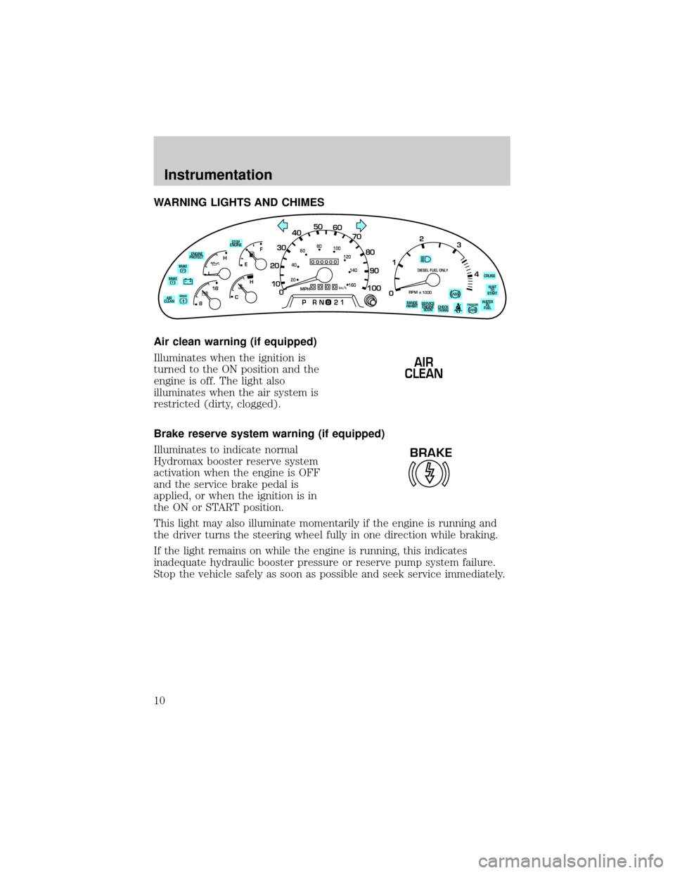
WARNING LIGHTS AND CHIMES
Air clean warning (if equipped)
Illuminates when the ignition is
turned to the ON position and the
engine is off. The light also
illuminates when the air system is
restricted (dirty, clogged).
Brake reserve system warning (if equipped)
Illuminates to indicate normal
Hydromax booster reserve system
activation when the engine is OFF
and the service brake pedal is
applied, or when the ignition is in
the ON or START position.
This light may also illuminate momentarily if the engine is running and
the driver turns the steering wheel fully in one direction while braking.
If the light remains on while the engine is running, this indicates
inadequate hydraulic booster pressure or reserve pump system failure.
Stop the vehicle safely as soon as possible and seek service immediately.
BRAKE
0
000000000
MPH20km/h
406080
100
120
140
160
010 20304050
60
70
80
90
100
TRAILERWATER
IN
FUELWAIT
TO
START STOP
ENGINE
ENGINE
PROTECT
AIR
CLEAN
CHECK
TRANS RANGE
INHIBITSERVICE
ENGINE
SOONCRUISE
LEF
H
RPM1000
DIESEL FUEL ONLY
X012
3
4PRN 218C 18
H
D
BRAKEBRAKE
AIR
CLEAN
BRAKE
Instrumentation
10
Page 17 of 240

GAUGES
Fuel gauge
Displays approximately how much
fuel is in the fuel tank (when the
key is in the ON position). The fuel
gauge may vary slightly when the
vehicle is in motion or after
refueling. The ignition should be in
the OFF position while the vehicle is
being refueled. When the gauge first
indicates empty, there is a small
amount of reserve fuel in the tank.
When refueling the vehicle from an empty indication, the amount of fuel
that can be added will be less than the advertised capacity due to the
reserve fuel.
Engine coolant temperature gauge
Indicates the temperature of the
engine coolant. At normal operating
temperature, the needle remains
within the normal area (the area
between the ªHº and ªCº). If it
enters the red section, the engine is
overheating. Stop the vehicle as
soon as safely possible, switch off
the engine immediately and let the
engine cool. Refer toEngine
coolantin theMaintenance and
carechapter.
BRAKE
0
000000000
MPH20km/h
406080
100
120
140
160
010 20304050
60
70
80
90
100
TRAILERWATER
IN
FUELWAIT
TO
START STOP
ENGINE
ENGINE
PROTECT
AIR
CLEAN
CHECK
TRANS RANGE
INHIBITSERVICE
ENGINE
SOONCRUISE
LEF
H
RPM1000
DIESEL FUEL ONLY
X012
3
4PRN 218C 18
H
D
BRAKEBRAKE
EF
H
C
Instrumentation
17
Page 74 of 240
Trailer hook up lamps Ð F650 SuperCrewzer only
Press the control to activate the
trailer lamps.
Press the control to deactivate the
trailer lamps.
Heated Mirrors Ð F650 SuperCrewzer only
Press this control to remove ice,
mist and fog from the mirrors. This
feature will automatically turn off
after 10 minutes.
Do not remove ice from the mirrors
with a scraper or attempt to
readjust the mirror glass if it is
frozen in place. These actions could
cause damage to the glass and
mirrors.
Interior Lamps
Map lamps (if equipped)
To turn on the map lamps, press the
control next to each lamp.
Controls and features
74
Page 77 of 240
2. Move the control in the direction
you wish to tilt the mirror.
3. Return to the center position to lock mirrors in place.
HEATED TELESCOPING TRAILER TOW MIRRORS
Manually pull the mirror outward or
inward as desired. Pull the mirrors
inward carefully when driving
through a narrow space.
MIRRORS
With the doors closed and the seat
adjusted for proper comfort, move
the mirrors to maximize rear
viewing area by adjusting the
western mirrors left or right as
required.
Adjust the auxiliary convex mirrors.
Convex mirrors are a ball-stud
design for precise adjustment to
maximize viewing area.
MIRRORS
L R
Controls and features
77
Page 118 of 240

Block the wheels to prevent the vehicle from moving.
Unexpected and possibly sudden vehicle movement may occur if
these precautions are not taken.
Impact wrenches should not be used as they may damage the piston and
prevent proper caging of the spring. Do not apply more than 68 Nm
(50 lb-ft) torque to the release bolt nut.
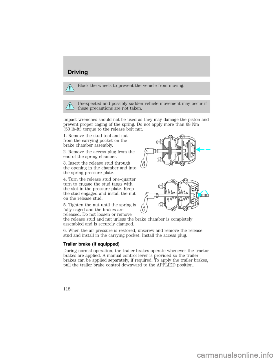
1. Remove the stud tool and nut
from the carrying pocket on the
brake chamber assembly.
2. Remove the access plug from the
end of the spring chamber.
3. Insert the release stud through
the opening in the chamber and into
the spring pressure plate.
4. Turn the release stud one-quarter
turn to engage the stud tangs with
the slot in the pressure plate. Keep
the stud engaged and install the nut
on the release stud.
5. Tighten the nut until the spring is
fully caged and the brakes are
released. Do not loosen or remove
the release stud and nut unless the brake chamber is completely
assembled and is securely clamped.
6. When the air pressure is restored, unscrew and remove the release
stud and install in the carrying pocket. Install the access plug.
Trailer brake (if equipped)
During normal operation, the trailer brakes operate whenever the tractor
brakes are applied. A manual control lever is provided so the trailer
brakes can be applied separately, if required. To apply the trailer brakes,
pull the trailer brake control downward to the APPLIED position.
Driving
118