Page 2 of 240

The following warning may be required by California law:
CALIFORNIA Proposition 65 Warning
WARNING:Engine exhaust, some of its constituents, and
certain vehicle components contain or emit chemicals known to
the State of California to cause cancer and birth defects or other
reproductive harm. In addition, certain fluids contained in vehicles and
certain products of component wear contain or emit chemicals known
to the State of California to cause cancer and birth defects or other
reproductive harm.
ICONS
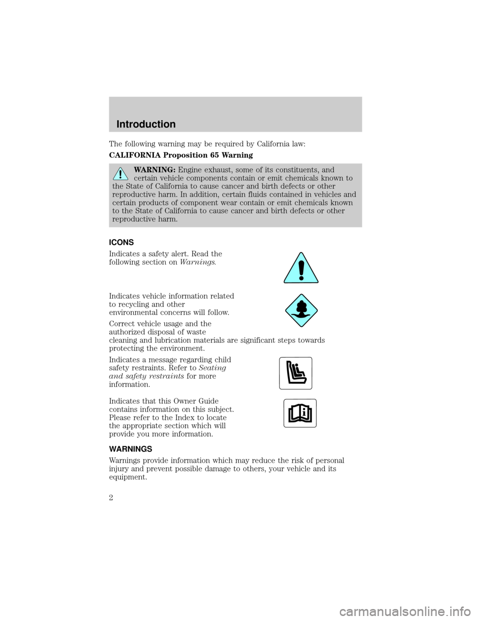
Indicates a safety alert. Read the
following section onWarnings.
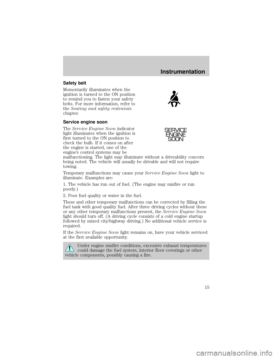
Indicates vehicle information related
to recycling and other
environmental concerns will follow.
Correct vehicle usage and the
authorized disposal of waste
cleaning and lubrication materials are significant steps towards
protecting the environment.
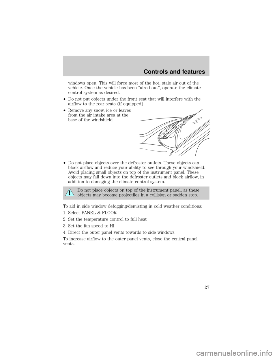
Indicates a message regarding child
safety restraints. Refer toSeating
and safety restraintsfor more
information.
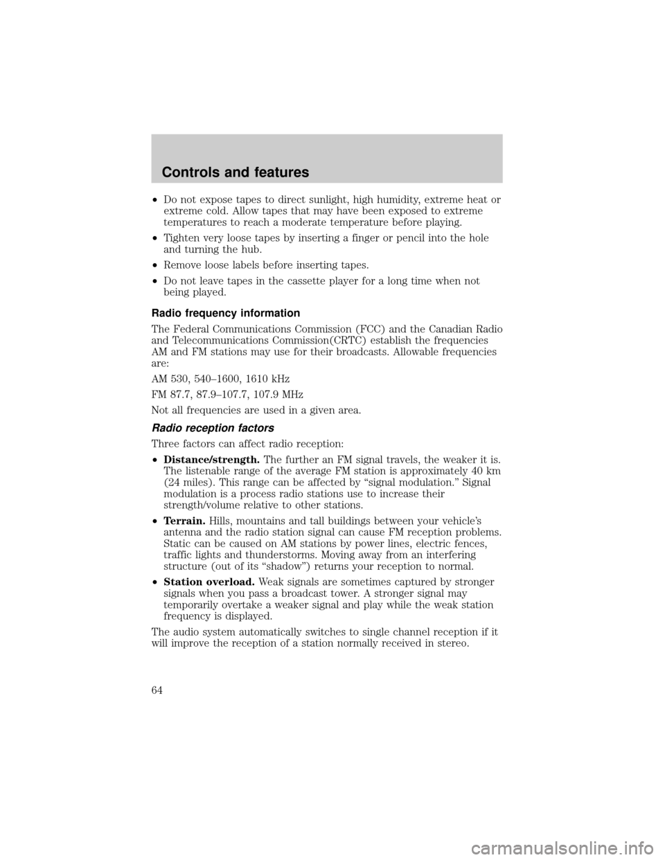
Indicates that this Owner Guide
contains information on this subject.
Please refer to the Index to locate
the appropriate section which will
provide you more information.
WARNINGS
Warnings provide information which may reduce the risk of personal
injury and prevent possible damage to others, your vehicle and its
equipment.
Introduction
2
Page 15 of 240

Safety belt
Momentarily illuminates when the
ignition is turned to the ON position
to remind you to fasten your safety
belts. For more information, refer to
theSeating and safety restraints
chapter.
Service engine soon
TheService Engine Soonindicator
light illuminates when the ignition is
first turned to the ON position to
check the bulb. If it comes on after
the engine is started, one of the
engine's control systems may be
malfunctioning. The light may illuminate without a driveability concern
being noted. The vehicle will usually be drivable and will not require
towing.
Temporary malfunctions may cause yourService Engine Soonlight to
illuminate. Examples are:
1. The vehicle has run out of fuel. (The engine may misfire or run
poorly.)
2. Poor fuel quality or water in the fuel.
These and other temporary malfunctions can be corrected by filling the
fuel tank with good quality fuel. After three driving cycles without these
or any other temporary malfunctions present, theService Engine Soon
light should turn off. (A driving cycle consists of a cold engine startup
followed by mixed city/highway driving.) No additional vehicle service is
required.
If theService Engine Soonlight remains on, have your vehicle serviced
at the first available opportunity.
Under engine misfire conditions, excessive exhaust temperatures
could damage the fuel system, interior floor coverings or other
vehicle components, possibly causing a fire.
SERVICE
ENGINE
SOON
Instrumentation
15
Page 22 of 240
Foglamp control (if equipped)
The headlamp control also operates
the foglamps. The foglamps can be
turned on only when the headlamp
control is in the
position and
the high beams are not turned on.
Pull headlamp control towards you
to turn foglamps on. The foglamp
indicator light
will illuminate.
AUXILIARY POWER POINT
The auxiliary power point is located
on the instrument panel.
Do not plug optional electrical
accessories into the cigarette lighter.
Use the power point.
CLIMATE CONTROL SYSTEM
Heater only system (if equipped)
Fan speed control
Controls the volume of air circulated
in the vehicle.
POWER POINT
OFF
Controls and features
22
Page 27 of 240

windows open. This will force most of the hot, stale air out of the
vehicle. Once the vehicle has been ªaired outº, operate the climate
control system as desired.
²Do not put objects under the front seat that will interfere with the
airflow to the rear seats (if equipped).
²Remove any snow, ice or leaves
from the air intake area at the
base of the windshield.
²Do not place objects over the defroster outlets. These objects can
block airflow and reduce your ability to see through your windshield.
Avoid placing small objects on top of the instrument panel. These
objects may fall down into the defroster outlets and block airflow, in
addition to damaging the climate control system.
Do not place objects on top of the instrument panel, as these
objects may become projectiles in a collision or sudden stop.
To aid in side window defogging/demisting in cold weather conditions:
1. Select PANEL & FLOOR
2. Set the temperature control to full heat
3. Set the fan speed to HI
4. Direct the outer panel vents towards to side windows
To increase airflow to the outer panel vents, close the central panel
vents.
Controls and features
27
Page 64 of 240

²Do not expose tapes to direct sunlight, high humidity, extreme heat or
extreme cold. Allow tapes that may have been exposed to extreme
temperatures to reach a moderate temperature before playing.
²Tighten very loose tapes by inserting a finger or pencil into the hole
and turning the hub.
²Remove loose labels before inserting tapes.
²Do not leave tapes in the cassette player for a long time when not
being played.
Radio frequency information
The Federal Communications Commission (FCC) and the Canadian Radio
and Telecommunications Commission(CRTC) establish the frequencies
AM and FM stations may use for their broadcasts. Allowable frequencies
are:
AM 530, 540±1600, 1610 kHz
FM 87.7, 87.9±107.7, 107.9 MHz
Not all frequencies are used in a given area.
Radio reception factors
Three factors can affect radio reception:
²Distance/strength.The further an FM signal travels, the weaker it is.
The listenable range of the average FM station is approximately 40 km
(24 miles). This range can be affected by ªsignal modulation.º Signal
modulation is a process radio stations use to increase their
strength/volume relative to other stations.
²Terrain.Hills, mountains and tall buildings between your vehicle's
antenna and the radio station signal can cause FM reception problems.
Static can be caused on AM stations by power lines, electric fences,
traffic lights and thunderstorms. Moving away from an interfering
structure (out of its ªshadowº) returns your reception to normal.
²Station overload.Weak signals are sometimes captured by stronger
signals when you pass a broadcast tower. A stronger signal may
temporarily overtake a weaker signal and play while the weak station
frequency is displayed.
The audio system automatically switches to single channel reception if it
will improve the reception of a station normally received in stereo.
Controls and features
64
Page 66 of 240
HIGH BEAMS
Push forward to activate.
Pull toward you to deactivate.
FLASH TO PASS
Pull toward you to activate and
release to deactivate.
SPEED CONTROL (IF EQUIPPED)
To turn speed control on-except Caterpillar/Cummins engines
²Press ON.
Vehicle speed cannot be controlled
until the vehicle is traveling at or
above 48 km/h (30 mph).
Do not use the speed control in heavy traffic or on roads that
are winding, slippery, or unpaved.
ON
OFF
Controls and features
66
Page 77 of 240
2. Move the control in the direction
you wish to tilt the mirror.
3. Return to the center position to lock mirrors in place.
HEATED TELESCOPING TRAILER TOW MIRRORS
Manually pull the mirror outward or
inward as desired. Pull the mirrors
inward carefully when driving
through a narrow space.
MIRRORS
With the doors closed and the seat
adjusted for proper comfort, move
the mirrors to maximize rear
viewing area by adjusting the
western mirrors left or right as
required.
Adjust the auxiliary convex mirrors.
Convex mirrors are a ball-stud
design for precise adjustment to
maximize viewing area.
MIRRORS
L R
Controls and features
77
Page 81 of 240
Replacing the battery
The remote transmitter is powered by one coin type three-volt lithium
battery CR2032 or equivalent. Typical operating range will allow you to
be up to 10 meters (33 feet) away from your vehicle. A decrease in
operating range can be caused by:
²weather conditions
²nearby radio towers
²structures around the vehicle
²other vehicles parked next to the vehicle
To replace the battery:
1. Twist a thin coin between the two
halves of the transmitter near the
key ring. DO NOT TAKE THE
FRONT PART OF THE
TRANSMITTER APART.
2. Place the positive (+) side of new
battery in the same orientation.
Refer to the diagram inside the
transmitter unit.
3. Snap the two halves back
together.
Replacement of the battery willnotcause the remote transmitter to
become deprogrammed from your vehicle. The remote transmitter should
operate normally after battery replacement.
Controls and features
81