2001 FORD F650 lights
[x] Cancel search: lightsPage 10 of 240

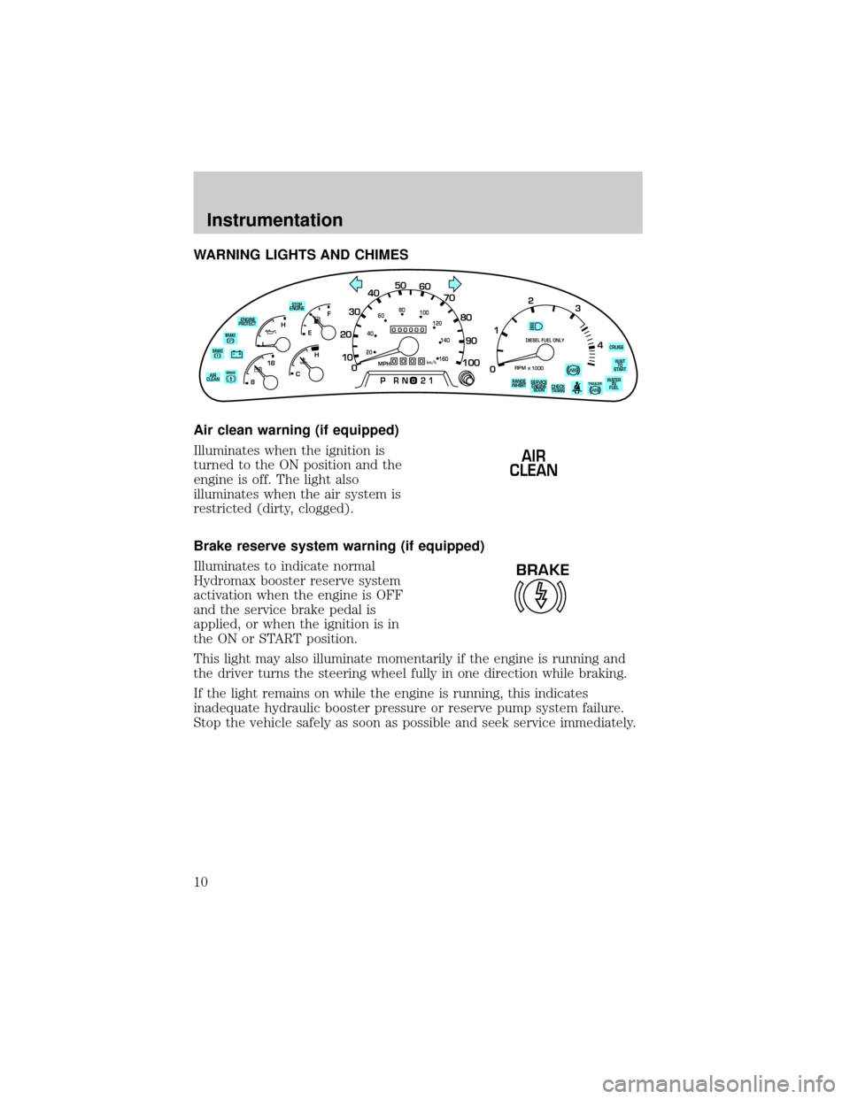
WARNING LIGHTS AND CHIMES
Air clean warning (if equipped)
Illuminates when the ignition is
turned to the ON position and the
engine is off. The light also
illuminates when the air system is
restricted (dirty, clogged).
Brake reserve system warning (if equipped)
Illuminates to indicate normal
Hydromax booster reserve system
activation when the engine is OFF
and the service brake pedal is
applied, or when the ignition is in
the ON or START position.
This light may also illuminate momentarily if the engine is running and
the driver turns the steering wheel fully in one direction while braking.
If the light remains on while the engine is running, this indicates
inadequate hydraulic booster pressure or reserve pump system failure.
Stop the vehicle safely as soon as possible and seek service immediately.
BRAKE
0
000000000
MPH20km/h
406080
100
120
140
160
010 20304050
60
70
80
90
100
TRAILERWATER
IN
FUELWAIT
TO
START STOP
ENGINE
ENGINE
PROTECT
AIR
CLEAN
CHECK
TRANS RANGE
INHIBITSERVICE
ENGINE
SOONCRUISE
LEF
H
RPM1000
DIESEL FUEL ONLY
X012
3
4PRN 218C 18
H
D
BRAKEBRAKE
AIR
CLEAN
BRAKE
Instrumentation
10
Page 12 of 240

Engine protect warning (Cummins engine only)
Illuminates when there is a fault in
the electronic subsystem but the
vehicle can be driven, and indicates
one of the following conditions:
²low oil pressure
²low coolant level
²high coolant temperature
²high intake manifold temperature
Refer to the Engine Operator's Manual.
Stop engine (if equipped)
This light is used in conjunction
with the electronic engine control.
Refer to the Engine Operator's
Manual for specific information
regarding this feature.
If the engine shuts down, it can be restarted and operated for 30 seconds
at a time or until the problem is corrected. Refer toEngine shutdown
systemin theStartingchapter.
Drivers of electronically controlled engines should know the
extent of warning engine shutdown system before operating the
vehicle. This information can be obtained from your dealer.
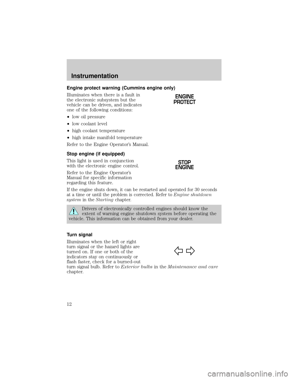
Turn signal
Illuminates when the left or right
turn signal or the hazard lights are
turned on. If one or both of the
indicators stay on continuously or
flash faster, check for a burned-out
turn signal bulb. Refer toExterior bulbsin theMaintenance and care
chapter.
ENGINE
PROTECT
STOP
ENGINE
Instrumentation
12
Page 54 of 240

CD select
CD mode may be entered by
pressing the CD control and the
LOAD control. Load the CD into the
audio system. The first track of the
disc will begin playing. After that,
CD play will begin where it stopped last.
If an alternative CD is desired, press the corresponding preset control
(1±6) of a loaded CD, or press the TUNE control to access the other
loaded CDs.
NO CD will display if the CD control is activated when there is not a CD
present in the audio system.
NO CD will illuminate in the display if the CD control and a present
number (that is currently empty) are pressed. The system will play the
next available disc.
If your vehicle is equipped with a CD changer, pressing the CD control
again will allow you to toggle between accessing the multi disc system
and the CD changer. The display will read CD or CDDJ.
Do not insert any promotional (odd shaped or sized) discs, or
discs with removable labels into the CD player as jamming may
occur.
Display description
Six circles are always lit in the digital display. These signify the six CD
slots in the audio system. When a disc is loaded into a particular slot
(1±6), the number inside that specific circle lights. If the circle is empty,
there is no CD in that particular slot.
Load
The load feature allows you to load
single CDs into the player internal
to the radio.
This six disc CD player is equipped with a CD door. Compact
discs should only be inserted into the player after the door has
been opened by the player. Do not attempt to force the door
open. Compact discs should only be loaded by pressing the LOAD
control.
CD AM
FM
LOAD
Controls and features
54
Page 64 of 240

²Do not expose tapes to direct sunlight, high humidity, extreme heat or
extreme cold. Allow tapes that may have been exposed to extreme
temperatures to reach a moderate temperature before playing.
²Tighten very loose tapes by inserting a finger or pencil into the hole
and turning the hub.
²Remove loose labels before inserting tapes.
²Do not leave tapes in the cassette player for a long time when not
being played.
Radio frequency information
The Federal Communications Commission (FCC) and the Canadian Radio
and Telecommunications Commission(CRTC) establish the frequencies
AM and FM stations may use for their broadcasts. Allowable frequencies
are:
AM 530, 540±1600, 1610 kHz
FM 87.7, 87.9±107.7, 107.9 MHz
Not all frequencies are used in a given area.
Radio reception factors
Three factors can affect radio reception:
²Distance/strength.The further an FM signal travels, the weaker it is.
The listenable range of the average FM station is approximately 40 km
(24 miles). This range can be affected by ªsignal modulation.º Signal
modulation is a process radio stations use to increase their
strength/volume relative to other stations.
²Terrain.Hills, mountains and tall buildings between your vehicle's
antenna and the radio station signal can cause FM reception problems.
Static can be caused on AM stations by power lines, electric fences,
traffic lights and thunderstorms. Moving away from an interfering
structure (out of its ªshadowº) returns your reception to normal.
²Station overload.Weak signals are sometimes captured by stronger
signals when you pass a broadcast tower. A stronger signal may
temporarily overtake a weaker signal and play while the weak station
frequency is displayed.
The audio system automatically switches to single channel reception if it
will improve the reception of a station normally received in stereo.
Controls and features
64
Page 73 of 240

4. Press and hold both controls.
After approximately four seconds,
the compass will enter zone setting
mode. Zone setting mode is
indicated when the display lights the
ªZONEº indicator.
5. Release both controls.
Subsequent pressing of either
control will increment the zone.
Press the control repeatedly until
the correct zone setting for your
geographic location is displayed on the trip computer.
6. To exit the zone setting mode and save the displayed zone in memory,
release both controls for greater than five seconds.
Compass calibration adjustment
Perform this adjustment in an open area free from steel structures and
high voltage lines.
For optimum calibration, turn off all electrical accessories (heater/air
conditioning, wipers, etc.) and make sure all vehicle doors are shut.
1. Locate the controls located in the overhead console.
2. Start the vehicle.
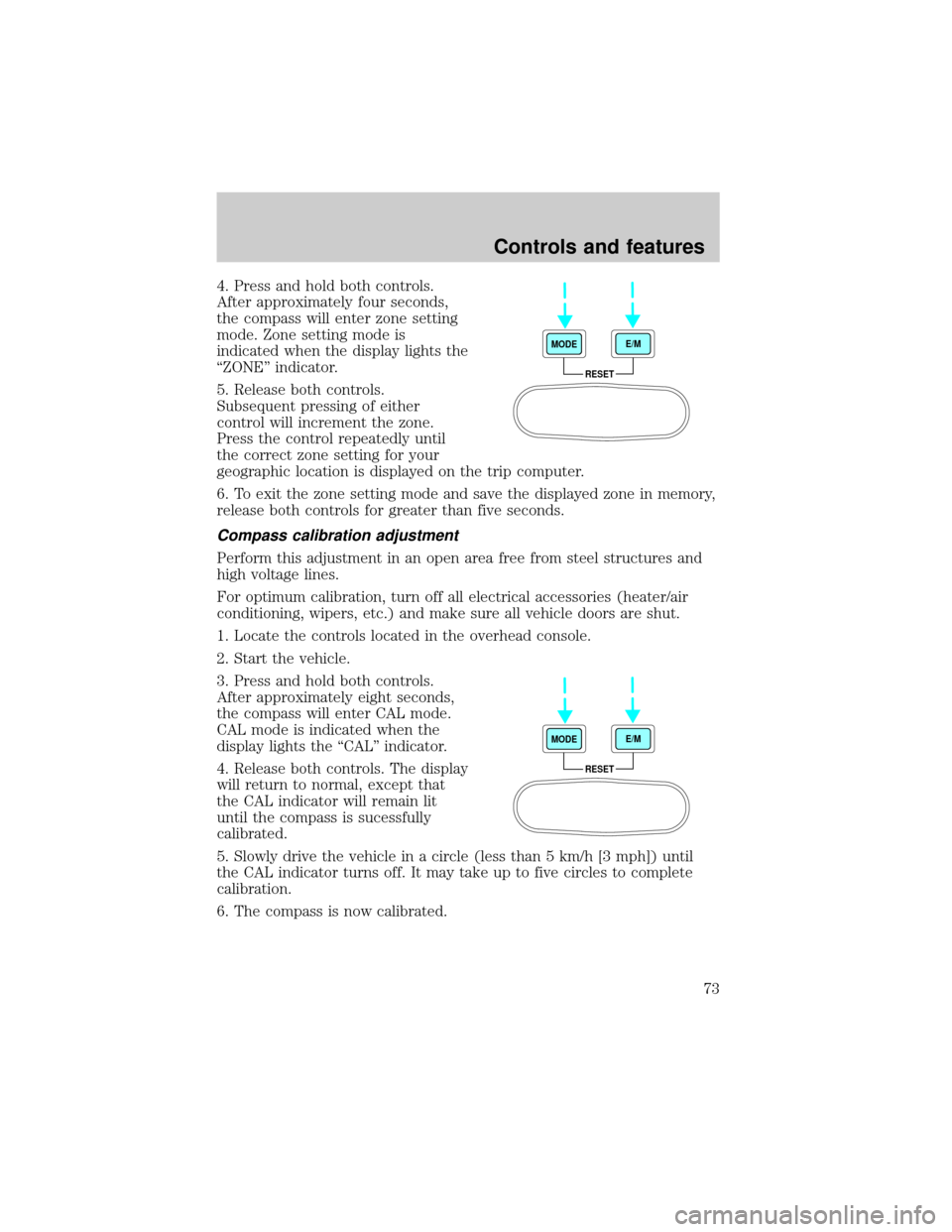
3. Press and hold both controls.
After approximately eight seconds,
the compass will enter CAL mode.
CAL mode is indicated when the
display lights the ªCALº indicator.
4. Release both controls. The display
will return to normal, except that
the CAL indicator will remain lit
until the compass is sucessfully
calibrated.
5. Slowly drive the vehicle in a circle (less than 5 km/h [3 mph]) until
the CAL indicator turns off. It may take up to five circles to complete
calibration.
6. The compass is now calibrated.
RESET MODEE/M
RESET MODEE/M
Controls and features
73
Page 79 of 240

Sounding a panic alarm
Press both controls to activate the
alarm. The horn will sound and the
lights will flash.
To deactivate the alarm, press both
controls again or turn the ignition to
ACC or ON.
This device complies with part 15 of
the FCC rules and with RS-210 of
Industry Canada. Operation is
subject to the following two
conditions: (1) This device may not cause harmful interference, and (2)
This device must accept any interference received, including interference
that may cause undesired operation.
Changes or modifications not expressly approved by the party
responsible for compliance could void the user's authority to
operate the equipment.
Illuminated entry
The illuminated entry system will turn on the interior lights when the
remote transmitter unlock control is pressed.
The illuminated entry system will turn off the interior lights if the
ignition switch is turned to the ON position, or if the remote transmitter
lock control is pressed, or after 25 seconds of illumination.
The inside lights will not turn off if:
²they have been turned on with the dimmer control or
²any door is open.
The battery save feature will turn off the interior lights 45 minutes after
the last door is closed, even if the dimmer control is on.
Controls and features
79
Page 143 of 240

HAZARD FLASHER
Use only in an emergency to warn traffic of vehicle breakdown,
approaching danger, etc. The hazard flashers can be operated when the
ignition is off.
²The hazard lights control is
located on top of the steering
column.
²Depress hazard lights control to
activate all hazard flashers
simultaneously.
²Depress control again to turn the
flashers off.
FUSES AND RELAYS
Fuses
If electrical components in the
vehicle are not working, a fuse may
have blown. Blown fuses are
identified by a broken wire within
the fuse. Check the appropriate
fuses before replacing any electrical
components.
Always replace a fuse with one that has the specified amperage
rating. Using a fuse with a higher amperage rating can cause
severe wire damage and could start a fire.
15
Roadside emergencies
143
Page 195 of 240

Using the right bulbs
Function Number of
bulbsTrade number
Headlamps 2 4652
Park/turn signal 2 1157
Sidemarker/rear marker lamp 5 red 12
(amber)194
Tail/stop lamp 4 2057
Backup 4 1156
Foglamp 2 899
Running board/courtesy lamp 6 194
License plate lamp 2 194
Cabmarker 5 168
Exterior visor lamp (if equipped) 4 194
Rear fender clearance 4
(a)
Rear identification 3 194
Dome lamp 1 105
To replace all instrument panel lights - see your dealer
(a)Replace entire lamp assembly; bulb is not serviceable.
AIMING THE HEADLAMPS
The headlamps on your vehicle are properly aimed at the assembly plant.
If your vehicle has been in an accident the alignment of your headlamps
should be checked by a qualified service technician.
MINOR TROUBLESHOOTING GUIDE
Diesel engine
For troubleshooting information, refer to the diesel engine operator's
manual.
If engine won't crank
For troubleshooting information, refer to the engine operator's manual.
If engine cranks but won't start
For troubleshooting information, refer to the engine operator's manual.
Maintenance and care
195