2001 FORD F350 heater
[x] Cancel search: heaterPage 23 of 288

4. Press and hold both trip
computer controls. After
approximately four seconds, the trip
computer will enter zone setting
mode. Zone setting mode is
indicated when the display lights the
“ZONE” indicator.
5. Release both controls.
Subsequent pressing of either
control will increment the zone.
Press the control repeatedly until
the correct zone setting for your geographic location is displayed on the
trip computer.
6. To exit the zone setting mode and save the displayed zone in memory,
release both controls for greater than five seconds.
Compass calibration adjustment
Perform this adjustment in an open area free from steel structures and
high voltage lines.
For optimum calibration, turn off all electrical accessories (heater/air
conditioning, wipers, etc.) and make sure all vehicle doors are shut.
1. Locate the trip computer located in the overhead console.
2. Start the vehicle.
3. Press and hold both trip
computer controls. After
approximately eight seconds, the
trip computer will enter CAL mode.
CAL mode is indicated when the
display lights the “CAL” indicator.
4. Release both controls. The display
will return to normal, except that
the CAL indicator will remain lit
until the compass is sucessfully
calibrated.
5. Slowly drive the vehicle in a circle (less than 5 km/h [3 mph]) until
the CAL indicator turns off. It may take up to five circles to complete
calibration.
6. The compass is now calibrated.
Instrumentation
23
ProCarManuals.com
Page 29 of 288

Always keep the sensors (located on the rear bumper/fascia) free
from dirt, snow and ice (do not clean the sensors with sharp
objects). These elements may cause the system to operate
inaccurately.
If the vehicle sustains damage to the rear bumper/fascia, leaving
it misaligned or bent, the sensing zone may be altered causing
inaccurate measurement of obstacles or false alarms.
AUXILIARY POWER POINT
Power outlets are designed for
accessory plugs only. Do not
hang any type of accessory or
accessory bracket from the plug.
Improper use of the power
outlet can cause damage not
covered by your warranty.
The auxiliary power point is located
on the instrument panel.
Do not plug optional electrical accessories into the cigarette lighter. Use
the power point.
CLIMATE CONTROL SYSTEM
Heater only system (if equipped)
Fan speed control
Controls the volume of air circulated
in the vehicle.
POWER POINT
O
F
F
Controls and features
29
ProCarManuals.com
Page 30 of 288

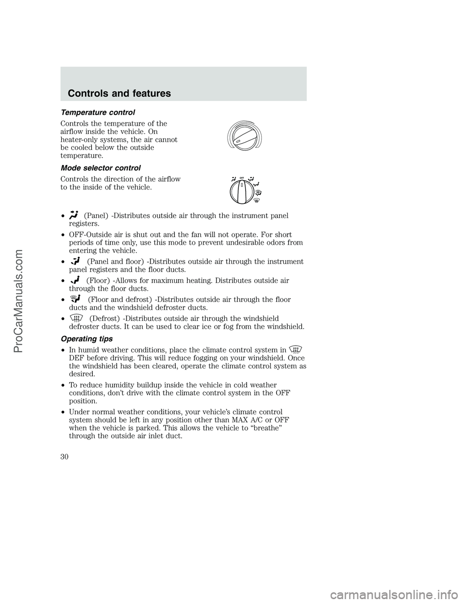
Temperature control
Controls the temperature of the
airflow inside the vehicle. On
heater-only systems, the air cannot
be cooled below the outside
temperature.
Mode selector control
Controls the direction of the airflow
to the inside of the vehicle.
•
(Panel) -Distributes outside air through the instrument panel
registers.
•OFF-Outside air is shut out and the fan will not operate. For short
periods of time only, use this mode to prevent undesirable odors from
entering the vehicle.
•
(Panel and floor) -Distributes outside air through the instrument
panel registers and the floor ducts.
•
(Floor) -Allows for maximum heating. Distributes outside air
through the floor ducts.
•
(Floor and defrost) -Distributes outside air through the floor
ducts and the windshield defroster ducts.
•
(Defrost) -Distributes outside air through the windshield
defroster ducts. It can be used to clear ice or fog from the windshield.
Operating tips
•In humid weather conditions, place the climate control system in
DEF before driving. This will reduce fogging on your windshield. Once
the windshield has been cleared, operate the climate control system as
desired.
•To reduce humidity buildup inside the vehicle in cold weather
conditions, don’t drive with the climate control system in the OFF
position.
•Under normal weather conditions, your vehicle’s climate control
system should be left in any position other than MAX A/C or OFF
when the vehicle is parked. This allows the vehicle to “breathe”
through the outside air inlet duct.
O
F
F
Controls and features
30
ProCarManuals.com
Page 129 of 288

Using the engine block heater (if equipped)
An engine block heater warms the
engine coolant, which improves
starting, warms up the engine faster
and allows the heater-defroster
system to respond quickly. Use of an
engine block heater is strongly
recommended if you live in a region
where temperatures reach -23°C
(-10°F) or below.
For best results, plug the heater in
at least three hours before starting the vehicle. Using the heater for
longer than three hours will not harm the engine, so the heater can be
plugged in the night before starting the vehicle.
To prevent electrical shock, do not use your heater with
ungrounded electrical systems or two-pronged (cheater)
adapters.
Guarding against exhaust fumes
Although odorless and colorless, carbon monoxide is present in exhaust
fumes. Take precautions to avoid its dangerous effects.
If you ever smell exhaust fumes of any kind inside your vehicle,
have your dealer inspect and fix your vehicle immediately. Do
not drive if you smell exhaust fumes. These fumes are harmful and
could kill you.
Have the exhaust and body ventilation systems checked whenever:
•the vehicle is raised for service
•the sound of the exhaust system changes
•the vehicle has been damaged in a collision
Starting
129
ProCarManuals.com
Page 174 of 288

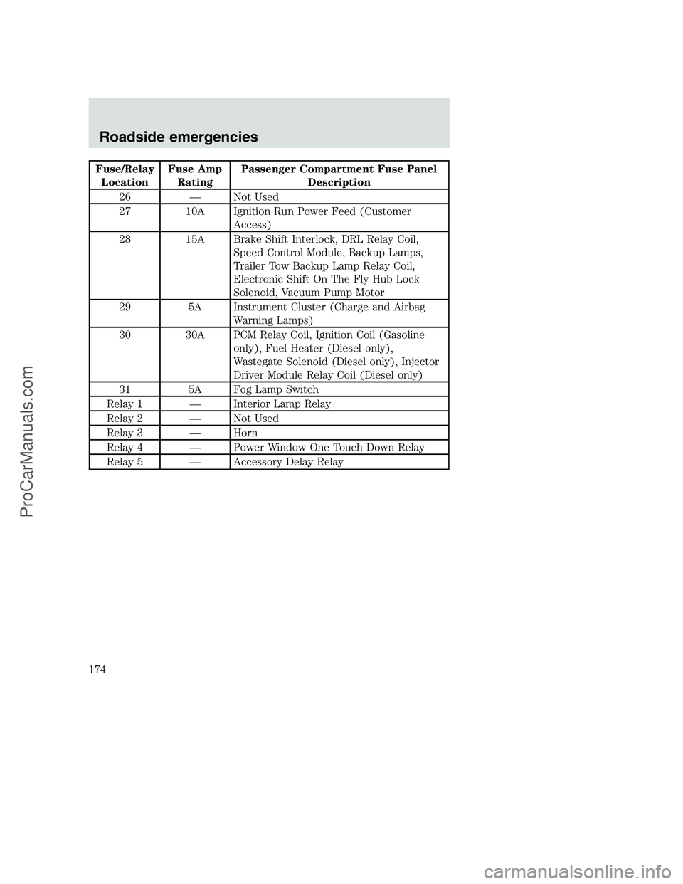
Fuse/Relay
LocationFuse Amp
RatingPassenger Compartment Fuse Panel
Description
26 — Not Used
27 10A Ignition Run Power Feed (Customer
Access)
28 15A Brake Shift Interlock, DRL Relay Coil,
Speed Control Module, Backup Lamps,
Trailer Tow Backup Lamp Relay Coil,
Electronic Shift On The Fly Hub Lock
Solenoid, Vacuum Pump Motor
29 5A Instrument Cluster (Charge and Airbag
Warning Lamps)
30 30A PCM Relay Coil, Ignition Coil (Gasoline
only), Fuel Heater (Diesel only),
Wastegate Solenoid (Diesel only), Injector
Driver Module Relay Coil (Diesel only)
31 5A Fog Lamp Switch
Relay 1 — Interior Lamp Relay
Relay 2 — Not Used
Relay 3 — Horn
Relay 4 — Power Window One Touch Down Relay
Relay 5 — Accessory Delay Relay
Roadside emergencies
174
ProCarManuals.com
Page 191 of 288

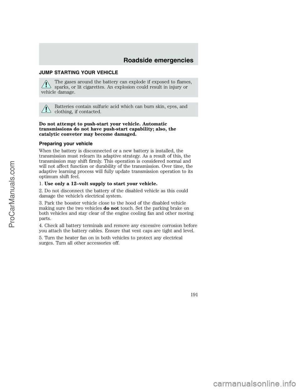
JUMP STARTING YOUR VEHICLE
The gases around the battery can explode if exposed to flames,
sparks, or lit cigarettes. An explosion could result in injury or
vehicle damage.
Batteries contain sulfuric acid which can burn skin, eyes, and
clothing, if contacted.
Do not attempt to push-start your vehicle. Automatic
transmissions do not have push-start capability; also, the
catalytic conveter may become damaged.
Preparing your vehicle
When the battery is disconnected or a new battery is installed, the
transmission must relearn its adaptive strategy. As a result of this, the
transmission may shift firmly. This operation is considered normal and
will not affect function or durability of the transmission. Over time, the
adaptive learning process will fully update transmission operation to its
optimum shift feel.
1.Use only a 12–volt supply to start your vehicle.
2. Do not disconnect the battery of the disabled vehicle as this could
damage the vehicle’s electrical system.
3. Park the booster vehicle close to the hood of the disabled vehicle
making sure the two vehiclesdo nottouch. Set the parking brake on
both vehicles and stay clear of the engine cooling fan and other moving
parts.
4. Check all battery terminals and remove any excessive corrosion before
you attach the battery cables. Ensure that vent caps are tight and level.
5. Turn the heater fan on in both vehicles to protect any electrical
surges. Turn all other accessories off.
Roadside emergencies
191
ProCarManuals.com
Page 272 of 288

Comfort and convenience
Air conditioner
Cargo organizers
Cargo storage bin
Cargo trays
Engine block heaters
Manual sliding rear window
Power sliding rear window
Tire step
Travel equipment
Auto headlamp system with Daytime Running Lights (DRL)
Bed Tent
Bumper mounted bike courier
Daytime running lights (DRL)
Electrochromic inside mirror with compass
Electrochromic inside mirror with compass and temperature display
Fog lights
Heavy-duty battery
Home link with travel note sun visor
Off road lights
Pickup box rails
Running boards and tubular running bars
Running boards diamond plate
Seatback organizer
Speed control
Towing mirrors
Trailer hitch, Class IV
Trailer hitch bars and balls
Trailer hitch mounted bike carrier
Trailer hitch wiring adaptor
Trailer wiring harness
Customer assistance
272
ProCarManuals.com
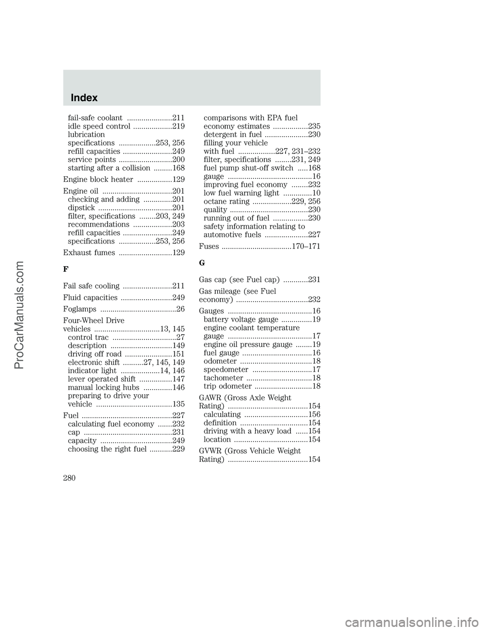
Page 280 of 288

fail-safe coolant ......................211
idle speed control ...................219
lubrication
specifications ..................253, 256
refill capacities ........................249
service points ..........................200
starting after a collision .........168
Engine block heater .................129
Engine oil ..................................201
checking and adding ..............201
dipstick ....................................201
filter, specifications ........203, 249
recommendations ...................203
refill capacities ........................249
specifications ..................253, 256
Exhaust fumes ..........................129
F
Fail safe cooling ........................211
Fluid capacities .........................249
Foglamps .....................................26
Four-Wheel Drive
vehicles ................................13, 145
control trac ...............................27
description ..............................149
driving off road .......................151
electronic shift ..........27, 145, 149
indicator light ...................14, 146
lever operated shift ................147
manual locking hubs ..............146
preparing to drive your
vehicle .....................................135
Fuel ............................................227
calculating fuel economy .......232
cap ...........................................231
capacity ...................................249
choosing the right fuel ...........229comparisons with EPA fuel
economy estimates .................235
detergent in fuel .....................230
filling your vehicle
with fuel ..................227, 231–232
filter, specifications ........231, 249
fuel pump shut-off switch .....168
gauge .........................................16
improving fuel economy ........232
low fuel warning light ..............10
octane rating ...................229, 256
quality ......................................230
running out of fuel .................230
safety information relating to
automotive fuels .....................227
Fuses ..................................170–171
G
Gas cap (see Fuel cap) ............231
Gas mileage (see Fuel
economy) ...................................232
Gauges .........................................16
battery voltage gauge ...............19
engine coolant temperature
gauge .........................................17
engine oil pressure gauge ........19
fuel gauge ..................................16
odometer ...................................18
speedometer .............................17
tachometer ................................18
trip odometer ............................18
GAWR (Gross Axle Weight
Rating) .......................................154
calculating ...............................156
definition .................................154
driving with a heavy load ......154
location ....................................154
GVWR (Gross Vehicle Weight
Rating) .......................................154
Index
280
ProCarManuals.com