Page 132 of 224
The fuses are coded as follows.
Fuse/Relay
LocationFuse Amp
RatingPassenger Compartment
Fuse Panel Description
1 15A Audio
2 5A Powertrain Control Module (PCM), Cluster
3 20A Cigar Lighter, OBD-II Scan Tool Connector
4 5A Remote Entry Module, Mirrors
5 15A Speed Control Module, Reverse Lamp,
Climate Mode Switch, Daytime Running
Lamp Relay
6 5A Cluster, Brake Shift Interlock Solenoid,
GEM Module
7 Ð Not Used
8 5A Radio, Remote Entry Module, GEM Module
9 Ð Not Used
10 Ð Not Used
FUSE1 12 22
21323
617 27
718 28
819 29
930
20
31 21 11 10
RELAY
5 RELAY
4 RELAY
3 RELAY
2 RELAY
1
31424
41525
51626
Roadside emergencies
132
Page 133 of 224

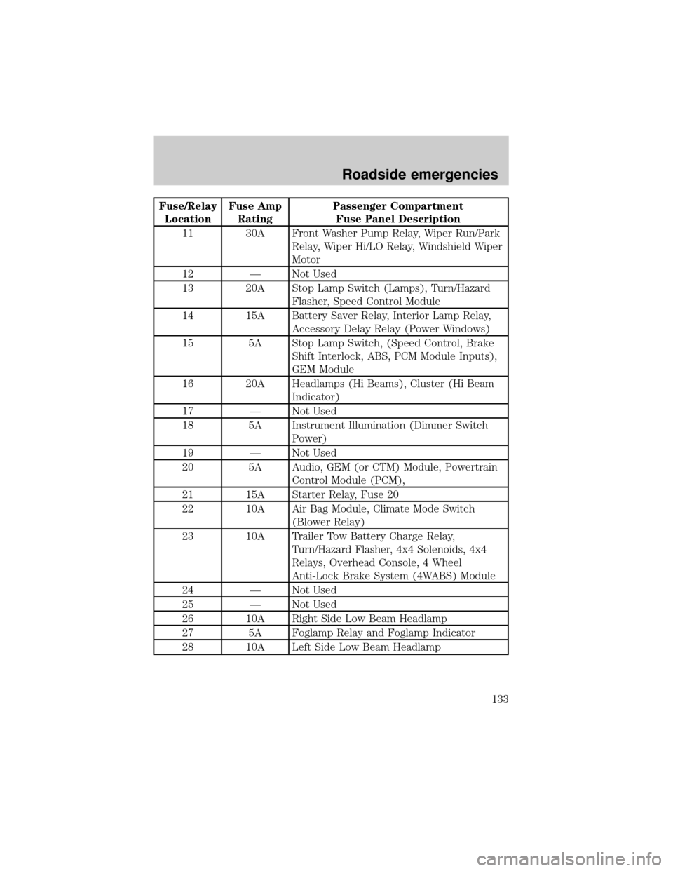
Fuse/Relay
LocationFuse Amp
RatingPassenger Compartment
Fuse Panel Description
11 30A Front Washer Pump Relay, Wiper Run/Park
Relay, Wiper Hi/LO Relay, Windshield Wiper
Motor
12 Ð Not Used
13 20A Stop Lamp Switch (Lamps), Turn/Hazard
Flasher, Speed Control Module
14 15A Battery Saver Relay, Interior Lamp Relay,
Accessory Delay Relay (Power Windows)
15 5A Stop Lamp Switch, (Speed Control, Brake
Shift Interlock, ABS, PCM Module Inputs),
GEM Module
16 20A Headlamps (Hi Beams), Cluster (Hi Beam
Indicator)
17 Ð Not Used
18 5A Instrument Illumination (Dimmer Switch
Power)
19 Ð Not Used
20 5A Audio, GEM (or CTM) Module, Powertrain
Control Module (PCM),
21 15A Starter Relay, Fuse 20
22 10A Air Bag Module, Climate Mode Switch
(Blower Relay)
23 10A Trailer Tow Battery Charge Relay,
Turn/Hazard Flasher, 4x4 Solenoids, 4x4
Relays, Overhead Console, 4 Wheel
Anti-Lock Brake System (4WABS) Module
24 Ð Not Used
25 Ð Not Used
26 10A Right Side Low Beam Headlamp
27 5A Foglamp Relay and Foglamp Indicator
28 10A Left Side Low Beam Headlamp
Roadside emergencies
133
Page 136 of 224

Fuse/Relay
LocationFuse Amp
RatingPower Distribution Box Description
17 Ð Not Used
18 15A* Powertrain Control Module, Fuel Injectors,
Fuel Pump Relay, Idle Air Control, Mass Air
Flow Sensor
19 10A* Trailer Tow Stop and Right Turn Lamp
20 10A* Trailer Tow Stop and Left Turn Lamp
21 Ð Not Used
22 Ð Not Used
23 15A* HEGO Sensor, Canister Vent, Automatic
Transmission, CMS Sensor
24 Ð Not Used
101 30A** Trailer Tow Battery Charge
102 50A** Four Wheel Antilock Brake Module
103 50A** Junction Block Battery Feed
104 30A** 4x4 Shift Motor & Clutch
105 40A** Climate Control Front Blower
106 Ð Not Used
107 Ð Not Used
108 30A** Trailer Tow Electric Brake
109 Ð Not Used
110 Ð Not Used
111 40A** Ignition Switch Battery Feed (Start and
Run Circuits)
112 30A** Drivers Power Seat, Adjustable Pedals
113 40A** Ignition Switch Battery Feed (Run and
Accessory Circuits)
114 Ð Not Used
115 20A** Power Door Locks
116 Ð Not Used
117 Ð Not Used
118 Ð Not Used
201 Ð Trailer Tow Park Lamp Relay
Roadside emergencies
136
Page 137 of 224

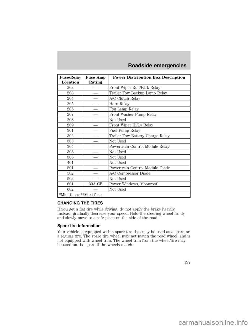
Fuse/Relay
LocationFuse Amp
RatingPower Distribution Box Description
202 Ð Front Wiper Run/Park Relay
203 Ð Trailer Tow Backup Lamp Relay
204 Ð A/C Clutch Relay
205 Ð Horn Relay
206 Ð Fog Lamp Relay
207 Ð Front Washer Pump Relay
208 Ð Not Used
209 Ð Front Wiper Hi/Lo Relay
301 Ð Fuel Pump Relay
302 Ð Trailer Tow Battery Charge Relay
303 Ð Not Used
304 Ð Powertrain Control Module Relay
305 Ð Not Used
306 Ð Not Used
401 Ð Not Used
501 Ð Powertrain Control Module Diode
502 Ð A/C Compressor Diode
503 Ð Not Used
601 30A CB Power Windows, Moonroof
602 Ð Not Used
*Mini fuses **Maxi fuses
CHANGING THE TIRES
If you get a flat tire while driving, do not apply the brake heavily.
Instead, gradually decrease your speed. Hold the steering wheel firmly
and slowly move to a safe place on the side of the road.
Spare tire information
Your vehicle is equipped with a spare tire that may be used as a spare or
a regular tire. The spare tire wheel may not match the road wheel, and is
not equipped with wheel trim. The wheel trim from the wheel/tire may
be used on the spare if the wheels match.
Roadside emergencies
137
Page 139 of 224

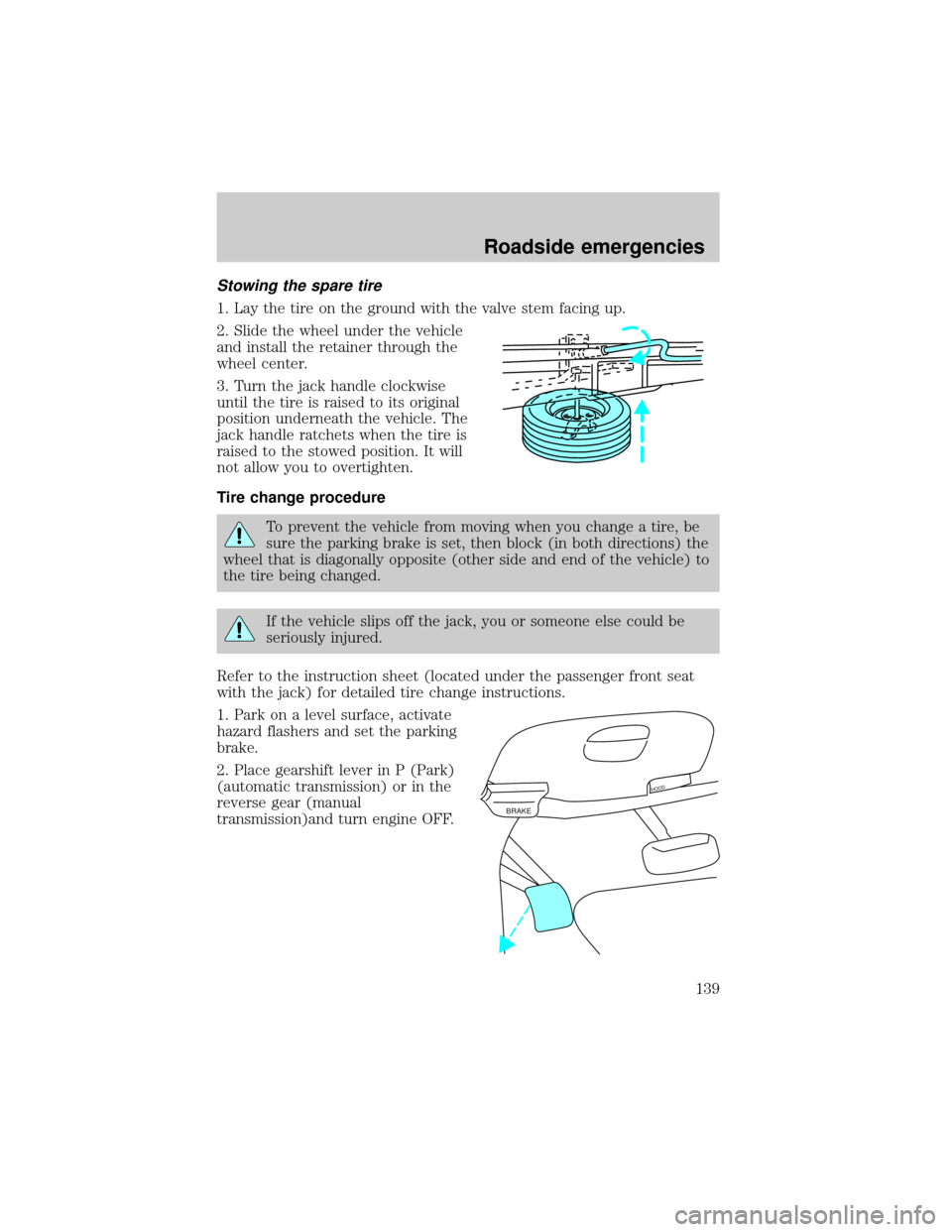
Stowing the spare tire
1. Lay the tire on the ground with the valve stem facing up.
2. Slide the wheel under the vehicle
and install the retainer through the
wheel center.
3. Turn the jack handle clockwise
until the tire is raised to its original
position underneath the vehicle. The
jack handle ratchets when the tire is
raised to the stowed position. It will
not allow you to overtighten.
Tire change procedure
To prevent the vehicle from moving when you change a tire, be
sure the parking brake is set, then block (in both directions) the
wheel that is diagonally opposite (other side and end of the vehicle) to
the tire being changed.
If the vehicle slips off the jack, you or someone else could be
seriously injured.
Refer to the instruction sheet (located under the passenger front seat
with the jack) for detailed tire change instructions.
1. Park on a level surface, activate
hazard flashers and set the parking
brake.
2. Place gearshift lever in P (Park)
(automatic transmission) or in the
reverse gear (manual
transmission)and turn engine OFF.
BRAKE
HOOD
Roadside emergencies
139
Page 140 of 224
3. Block the diagonally opposite
wheel.
4. Obtain the spare tire and jack
from their storage locations.
5. Use the tip of the lug wrench to
remove any wheel trim.
6. Loosen each wheel lug nut
one-half turn counterclockwise but
do not remove them until the wheel
is raised off the ground.
7. Position the jack according to the following guides and turn the jack
handle clockwise until the wheel is completely off the ground.
When one of the rear wheels is off the ground, the transmission
alone will not prevent the vehicle from moving or slipping off the
jack, even if the transmission is in P (Park) or in the reverse gear
(manual transmission). To prevent the vehicle from moving when you
change the tire, be sure that the parking brake is set and the
diagonally opposite wheel is blocked. If the vehicle slips off the jack,
someone could be seriously injured.
Roadside emergencies
140
Page 143 of 224

Do not attempt to push start your vehicle. Automatic
transmissions do not have push-start capability.
Preparing your vehicle
1.Use only a 12±volt supply to start your vehicle.
2. Do not disconnect the battery of the disabled vehicle as this could
damage the vehicle's electrical system.
3. Park the booster vehicle close to the hood of the disabled vehicle
making sure the two vehiclesdo nottouch. Set the parking brake on
both vehicles and stay clear of the engine cooling fan and other moving
parts.
4. Check all battery terminals and remove any excessive corrosion before
you attach the battery cables. Ensure that vent caps are tight and level.
5. Turn the heater fan on in both vehicles to protect any electrical
surges. Turn all other accessories off.
Connecting the jumper cables
1. Connect the positive (+) booster cable to the positive (+) terminal of
the discharged battery.
Note:In the illustrations,lightning boltsare used to designate the
assisting (boosting) battery.
+–+–
Roadside emergencies
143
Page 148 of 224

SERVICE RECOMMENDATIONS
To help you service your vehicle:
²We highlight do-it-yourself items in the engine compartment for easy
location.
²We provide a Scheduled Maintenance Guide which makes tracking
routine service easy.
If your vehicle requires professional service, your dealership can provide
necessary parts and service. Check your ªWarranty Guideº to find out
which parts and services are covered.
Use only recommended fuels, lubricants, fluids and service parts
conforming to specifications. Motorcraft parts are designed and built to
provide the best performance in your vehicle.
PRECAUTIONS WHEN SERVICING YOUR VEHICLE
Be especially careful when inspecting or servicing your vehicle.
²Do not work on a hot engine.
²When the engine is running, keep loose clothing, jewelry or long hair
away from moving parts.
²Do not work on a vehicle with the engine running in an enclosed
space, unless you are sure you have enough ventilation.
²Keep all lit cigarettes, open flames and other lit material away from
the battery and all fuel related parts.
If you disconnect the battery, the engine must ªrelearnº its idle
conditions before your vehicle will drive properly, as explained in the
Batterysection in this chapter.
Working with the engine off
1. Set the parking brake and ensure the gearshift is securely latched in P
(Park).
2. Turn off the engine and remove the key.
3. Block the wheels to prevent the vehicle from moving unexpectedly.
Working with the engine on
1. Set the parking brake and ensure the gearshift is securely latched in P
(Park).
2. Block the wheels to prevent the vehicle from moving unexpectedly.
Maintenance and care
148