Page 5 of 104
Panic AlarmEngine Oil
Engine CoolantEngine Coolant
Temperature
Do Not Open When HotBattery
Avoid Smoking, Flames,
or SparksBattery Acid
Explosive GasFan Warning
Power Steering FluidMaintain Correct Fluid
LevelMAX
MIN
Emission SystemEngine Air Filter
Passenger Compartment
Air FilterJack
Check fuel cap
Introduction
5
Page 7 of 104

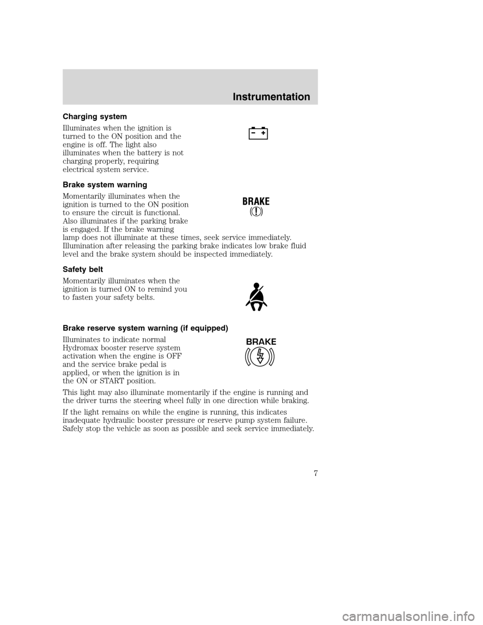
Charging system
Illuminates when the ignition is
turned to the ON position and the
engine is off. The light also
illuminates when the battery is not
charging properly, requiring
electrical system service.
Brake system warning
Momentarily illuminates when the
ignition is turned to the ON position
to ensure the circuit is functional.
Also illuminates if the parking brake
is engaged. If the brake warning
lamp does not illuminate at these times, seek service immediately.
Illumination after releasing the parking brake indicates low brake fluid
level and the brake system should be inspected immediately.
Safety belt
Momentarily illuminates when the
ignition is turned ON to remind you
to fasten your safety belts.
Brake reserve system warning (if equipped)
Illuminates to indicate normal
Hydromax booster reserve system
activation when the engine is OFF
and the service brake pedal is
applied, or when the ignition is in
the ON or START position.
This light may also illuminate momentarily if the engine is running and
the driver turns the steering wheel fully in one direction while braking.
If the light remains on while the engine is running, this indicates
inadequate hydraulic booster pressure or reserve pump system failure.
Safely stop the vehicle as soon as possible and seek service immediately.
BRAKE
Instrumentation
7
Page 12 of 104
Battery voltage gauge
This shows the battery voltage when
the ignition is in the ON position. If
the pointer moves and stays outside
the normal operating range (as
indicated), have the vehicle’s
electrical system checked as soon as
possible.
Engine coolant temperature gauge
Indicates the temperature of the
engine coolant. At normal operating
temperature, the needle remains
within the normal area (the area
between the “H” and “C”). If it
enters the red section, the engine is
overheating. Stop the vehicle as
soon as safely possible, switch off
the engine immediately and let the
engine cool. Refer toEngine
coolantin theMaintenance and
carechapter.
Never remove the coolant reservoir cap while the engine is
running or hot.
This gauge indicates the temperature of the engine coolant, not the
coolant level. If the coolant is not at its proper level the gauge indication
will not be accurate.
818
H
C
Instrumentation
12
Page 43 of 104

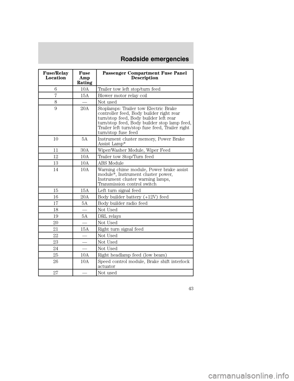
Fuse/Relay
LocationFuse
Amp
RatingPassenger Compartment Fuse Panel
Description
6 10A Trailer tow left stop/turn feed
7 15A Blower motor relay coil
8 — Not used
9 20A Stoplamps: Trailer tow Electric Brake
controller feed, Body builder right rear
turn/stop feed, Body builder left rear
turn/stop feed, Body builder stop lamp feed,
Trailer left turn/stop fuse feed, Trailer right
turn/stop fuse feed
10 5A Instrument cluster memory, Power Brake
Assist Lamp*
11 30A Wiper/Washer Module, Wiper Feed
12 10A Trailer tow Stop/Turn feed
13 10A ABS Module
14 10A Warning chime module, Power brake assist
module*, Instrument cluster power,
Instrument cluster warning lamps,
Transmission control switch
15 15A Left turn signal feed
16 20A Body builder battery (+12V) feed
17 5A Body builder radio feed
18 — Not Used
19 5A DRL relays
20 — Not Used
21 15A Right turn signal feed
22 — Not Used
23 — Not Used
24 — Not Used
25 10A Right headlamp feed (low beam)
26 10A Speed control module, Brake shift interlock
actuator
27 — Not used
Roadside emergencies
43
Page 44 of 104
Fuse/Relay
LocationFuse
Amp
RatingPassenger Compartment Fuse Panel
Description
28 — Not used
29 — Not used
30 — Not used
31 10A Left headlamp feed (low beam)
32 10A Backup lamp feed
33 — Not used
34 — Not used
35 20A Body builder high beam feed, High beam
indicator
36 — Not used
37 — Not used
38 10A Body builder accessory feed (run only)
39 — Not used
40 — Not used
41 10A Instrument illumination
42 — Not used
43 — Not used
44 — Not used
Relay 1 — Left turn signal relay
Relay 2 —— Courtesy lamps relay
Relay 3 Right turn signal relay
*Vehicles with Hydromax brake assist only
Power distribution box
The power distribution box is located in the engine compartment. The
power distribution box contains high-current fuses that protect your
vehicle’s main electrical systems from overloads.
Always disconnect the battery before servicing high current
fuses.
Roadside emergencies
44
Page 45 of 104
Always replace the cover to the Power Distribution Box before
reconnecting the battery or refilling fluid reservoirs.
If the battery has been disconnected and reconnected, refer to the
Batterysection of theMaintenance and carechapter.
The high-current fuses are coded as follows.
Fuse/Relay
LocationFuse
Amp
RatingPower Distribution Box Description
1 5A* Power Brake Assist Module***
2 10A* A/C System
3 20A* 4R100 Transmission, Vapor Management
Valve Solenoid, Heated Exhaust Gas Oxygen
(HEGO) Sensors
4 5A* Powertrain Control Module Memory
19 29
18 28
17 27
16 26
15 25
14 24
13
11 12
910
78
56
34
1223
22
21
20
6
5
4
3
2
1DIODE2
DIODE1
Roadside emergencies
45
Page 46 of 104

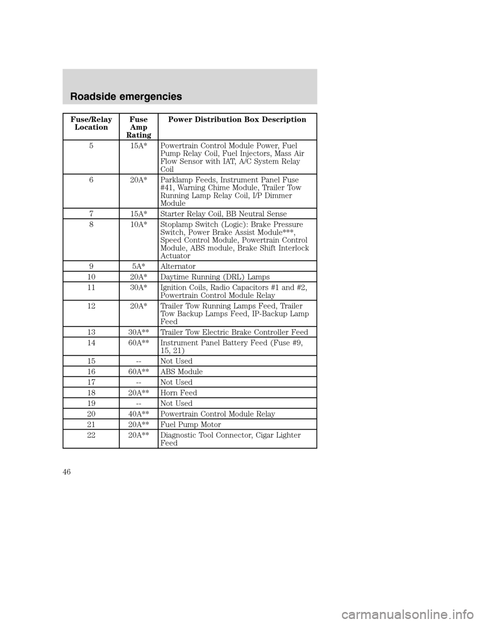
Fuse/Relay
LocationFuse
Amp
RatingPower Distribution Box Description
5 15A* Powertrain Control Module Power, Fuel
Pump Relay Coil, Fuel Injectors, Mass Air
Flow Sensor with IAT, A/C System Relay
Coil
6 20A* Parklamp Feeds, Instrument Panel Fuse
#41, Warning Chime Module, Trailer Tow
Running Lamp Relay Coil, I/P Dimmer
Module
7 15A* Starter Relay Coil, BB Neutral Sense
8 10A* Stoplamp Switch (Logic): Brake Pressure
Switch, Power Brake Assist Module***,
Speed Control Module, Powertrain Control
Module, ABS module, Brake Shift Interlock
Actuator
9 5A* Alternator
10 20A* Daytime Running (DRL) Lamps
11 30A* Ignition Coils, Radio Capacitors #1 and #2,
Powertrain Control Module Relay
12 20A* Trailer Tow Running Lamps Feed, Trailer
Tow Backup Lamps Feed, IP-Backup Lamp
Feed
13 30A** Trailer Tow Electric Brake Controller Feed
14 60A** Instrument Panel Battery Feed (Fuse #9,
15, 21)
15 -- Not Used
16 60A** ABS Module
17 -- Not Used
18 20A** Horn Feed
19 -- Not Used
20 40A** Powertrain Control Module Relay
21 20A** Fuel Pump Motor
22 20A** Diagnostic Tool Connector, Cigar Lighter
Feed
Roadside emergencies
46
Page 47 of 104
Fuse/Relay
LocationFuse
Amp
RatingPower Distribution Box Description
23 40A** Blower Motor Feed
24 40A** Instrument Panel Battery Feed (fuses #4,
10, 16)
25 50A** Ignition Switch Feed (Instrument Panel
Fuses #1, 5, 7, 11, 13, 14, 17, 19, PDB fuses
#7, 9, 11)
26 60A** Ignition Switch Feed (Instrument Panel
Fuses #5, 11, 17, 26, 32, 38)
27 30A** Multifunction Switch (Headlamps)
28 — Not Used
29 60A** Power Brake Assist Motor***
Relay 1 — Daytime Running Lamps On/Off Relay
Relay 2 — Fuel Pump Relay
Relay 3 — Horn Relay
Relay 4 — A/C System Relay
Relay 5 — Blower Motor Relay
Relay 6 — Powertrain Control Module Relay
Diode 1 — Powertrain Control Module Diode
Diode 2 — Park Brake Diode
* Mini Fuses ** Maxi Fuses ***Vehicles with Hydromax brake assist
only
Roadside emergencies
47