Page 182 of 288

Using a step bumper
The rear bumper is equipped with an integral hitch and requires only a
ball with a 19 mm (3/4 inch) shank diameter. The bumper has a 1 590 kg
(3 500 lb.) trailer weight and 159 kg (350 lb.) tongue weight capability.
Use a frame-mounted weight distributing hitch for trailers over 1 590 kg
(3 500 lb).
Driving while you tow
When towing a trailer:
²Ensure that you turn off your speed control. The speed control may
shut off automatically when you are towing on long, steep grades.
²Consult your local motor vehicle speed regulations for towing a trailer.
²Use a lower gear when towing up or down steep hills. This will
eliminate excessive downshifting and upshifting for optimum fuel
economy and transmission cooling.
²Anticipate stops and brake gradually.
Exceeding the GCWR rating may cause internal transmission
damage and void your warranty coverage.
Servicing after towing
If you tow a trailer for long distances, your vehicle will require more
frequent service intervals. Refer to your scheduled maintenance guide for
more information.
Trailer towing tips
²Practice turning, stopping and backing up before starting on a trip to
get the feel of the vehicle trailer combination. When turning, make
wider turns so the trailer wheels will clear curbs and other obstacles.
²Allow more distance for stopping with a trailer attached.
²The trailer tongue weight should be 10% of the loaded trailer weight.
²After you have traveled 80 km (50 miles), thoroughly check your
hitch, electrical connections and trailer wheel lug nuts.
²When stopped in traffic for long periods of time in hot weather, place
the gearshift in P (Park) and increase idle speed. This aids engine
cooling and air conditioner efficiency.
²Vehicles with trailers should not be parked on a grade. If you must
park on a grade, place wheel chocks under the trailer's wheels.
Driving
182
Page 186 of 288

Roadside coverage beyond basic warranty
In the United States, you may purchase additional roadside assistance
coverage beyond this period through the Ford Auto Club by contacting
your Ford or Lincoln Mercury dealer.
Similarly in Canada, you may purchase additional coverage beyond the
basic coverage period by consulting the Ford Roadside Assistance Club
brochure or by calling 1±877±294±CLUB (1±877±894±2582).
HAZARD FLASHER
Use only in an emergency to warn traffic of vehicle breakdown,
approaching danger, etc. The hazard flashers can be operated when the
ignition is off.
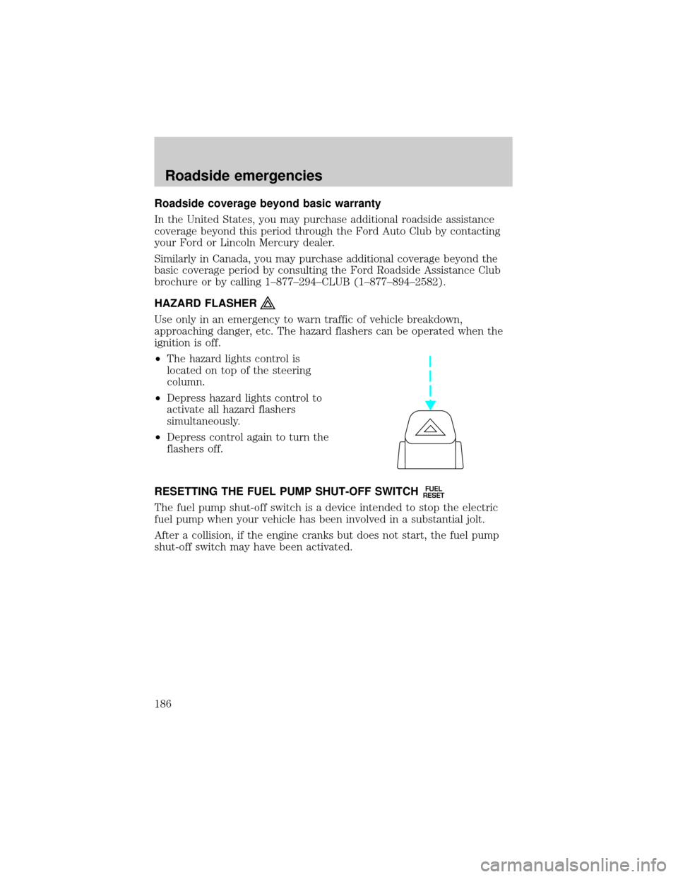
²The hazard lights control is
located on top of the steering
column.
²Depress hazard lights control to
activate all hazard flashers
simultaneously.
²Depress control again to turn the
flashers off.
RESETTING THE FUEL PUMP SHUT-OFF SWITCH
FUEL
RESET
The fuel pump shut-off switch is a device intended to stop the electric
fuel pump when your vehicle has been involved in a substantial jolt.
After a collision, if the engine cranks but does not start, the fuel pump
shut-off switch may have been activated.
Roadside emergencies
186
Page 192 of 288
Fuse/
Relay
LocationFuse
Amp
RatingPassenger Compartment Fuse Panel
Description
32 10A Heated Mirror
33 15A Headlamps, Daytime Running Lamps (DRL)
Module, Instrument Cluster
34 7.5A Rear Integrated Control Panel, CD
35 7.5A Rear Blower Motor (w/EATC)
36 7.5A EATC Memory, CD, Rear Integrated Control
Panel, Memory Seat, Message Center
Power distribution box
The power distribution box is
located in the engine compartment.
The power distribution box contains
high-current fuses that protect your
vehicle's main electrical systems
from overloads.
Always disconnect the battery before servicing high current
fuses.
Always replace the cover to the Power Distribution Box before
reconnecting the battery or refilling fluid reservoirs.
If the battery has been disconnected and reconnected, refer to the
Batterysection of theMaintenance and carechapter.
Roadside emergencies
192
Page 194 of 288
Fuse/
Relay
LocationFuse
Amp
RatingPower Distribution Box Description
5 Ð Not Used
6 10A* Powertrain Control Module
7 30A* 4 Wheel Anti-Lock System (4WABS) Module
8 15A* Rear Wiper Motor
9 20A* Fuel Pump Relay and RAP Module
10 15A* Horn Relay
11 15A* Parklamps Relay and Mainlight Switch
12 30A* Mainlight Switch and Multifunction Switch
13 15A* Heated Oxygen Sensor, EGR Vacuum
Regulator, EVR Solenoid, Camshaft Position
(CMP) Sensor, Canister Vent Solenoid
14 30A* Generator/Voltage Regulator
15 Ð Not Used
1 Ð Wiper Park Relay
2 Ð A/C Relay
3 Ð Wiper High/Low Relay
4 Ð PCM Power Relay
5 Ð Fuel Pump Relay
6 Ð Starter Relay
7 Ð Horn Relay
8 Ð Rear Wipe Down Relay
9 Ð Blower Motor Relay
10 Ð Rear Wipe Up Relay
1 Ð Not Used
1 Ð DRL Diode
2 Ð Electronic Engine Controls Diode
* Mini Fuses ** Maxi Fuses
Roadside emergencies
194
Page 196 of 288

Stowing the spare tire
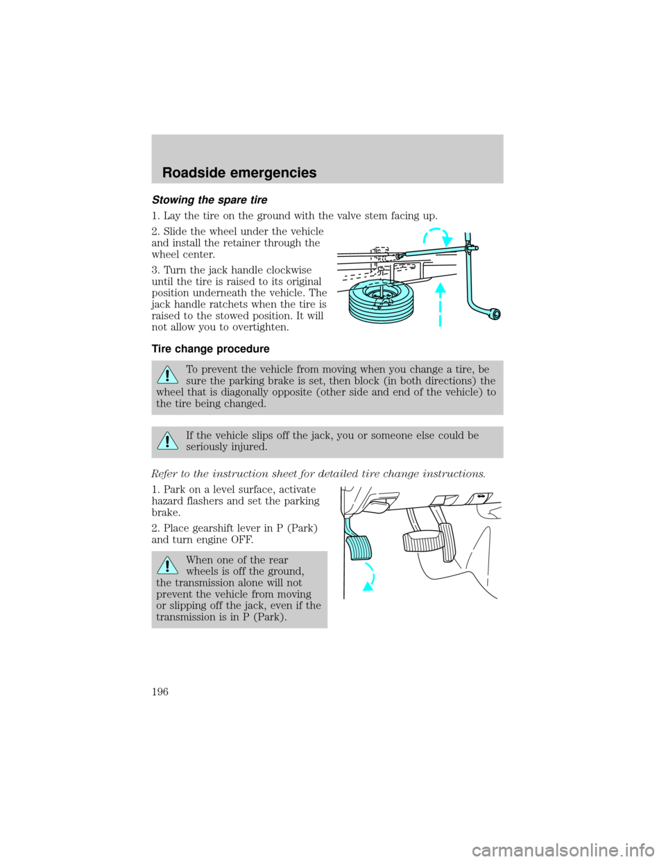
1. Lay the tire on the ground with the valve stem facing up.
2. Slide the wheel under the vehicle
and install the retainer through the
wheel center.
3. Turn the jack handle clockwise
until the tire is raised to its original
position underneath the vehicle. The
jack handle ratchets when the tire is
raised to the stowed position. It will
not allow you to overtighten.
Tire change procedure
To prevent the vehicle from moving when you change a tire, be
sure the parking brake is set, then block (in both directions) the
wheel that is diagonally opposite (other side and end of the vehicle) to
the tire being changed.
If the vehicle slips off the jack, you or someone else could be
seriously injured.
Refer to the instruction sheet for detailed tire change instructions.
1. Park on a level surface, activate
hazard flashers and set the parking
brake.
2. Place gearshift lever in P (Park)
and turn engine OFF.
When one of the rear
wheels is off the ground,
the transmission alone will not
prevent the vehicle from moving
or slipping off the jack, even if the
transmission is in P (Park).
Roadside emergencies
196
Page 198 of 288
²Front
²Rear
To lessen the risk of
personal injury, do not put
any part of your body under the
vehicle while changing a tire. Do
not start the engine when your
vehicle is on the jack. The jack is
only meant for changing the tire.
²Never use the front or rear
differential as a jacking point.
8. Remove the lug nuts with the lug wrench.
9. Replace the flat tire with the spare tire, making sure the valve stem is
facing outward. Reinstall the lug nuts, cone side in, until the wheel is
snug against the hub. Do not fully tighten the lug nuts until the wheel
has been lowered.
Roadside emergencies
198
Page 200 of 288

Preparing your vehicle
When the battery is disconnected or a new battery is installed, the
transmission must relearn its adaptive strategy. As a result of this, the
transmission may shift firmly. This operation is considered normal and
will not effect function or durability of the transmission. Over time, the
adaptive learning process will fully update transmission operation to its
optimum shift feel.
1.Use only a 12±volt supply to start your vehicle.
2. Do not disconnect the battery of the disabled vehicle as this could
damage the vehicle's electrical system.
3.
Park the booster vehicle close to the hood of the disabled vehicle
making sure the two vehiclesdo nottouch. Set the parking brake on both
vehicles and stay clear of the engine cooling fan and other moving parts.
4. Check all battery terminals and remove any excessive corrosion before
you attach the battery cables. Ensure that vent caps are tight and level.
5. Turn the heater fan on in both vehicles to protect any electrical
surges. Turn all other accessories off.
Connecting the jumper cables
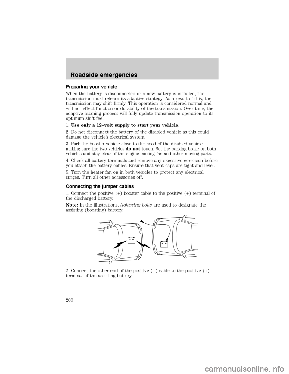
1. Connect the positive (+) booster cable to the positive (+) terminal of
the discharged battery.
Note:In the illustrations,lightning boltsare used to designate the
assisting (boosting) battery.
2. Connect the other end of the positive (+) cable to the positive (+)
terminal of the assisting battery.
+–+–
Roadside emergencies
200
Page 201 of 288
3. Connect the negative (-) cable to the negative (-) terminal of the
assisting battery.
4. Make the final connection of the negative (-) cable to an exposed
metal part of the stalled vehicle's engine, away from the battery and the
carburetor/fuel injection system.
Do notuse fuel lines, engine rocker covers or the intake manifold as
groundingpoints.
Do not connect the end of the second cable to the negative (-)
terminal of the battery to be jumped. A spark may cause an
explosion of the gases that surround the battery.
+–+–
+–+–
Roadside emergencies
201