2001 FORD EXPEDITION instrument panel
[x] Cancel search: instrument panelPage 63 of 280
economical and will cool the inside of the vehicle faster. Airflow is
from the instrument panel registers. This mode can also be used to
prevent undesirable odors from entering the vehicle.
•VENT-Distributes outside air through the instrument panel registers.
However, the air cannot be cooled below the outside temperature
because the air conditioning does not operate in this mode.
•PNL•FLR-Distributes outside air through the instrument panel
registers and the floor ducts. Heating and air conditioning capabilities
are provided in this mode. The air will be heated or cooled based on
the temperature selection. For added customer comfort, the air
distributed through the floor ducts will be slightly warmer than the air
sent to the instrument panel registers.
•FLOOR-Allows for maximum heating by distributing outside air
through the floor ducts. However, the air cannot be cooled below the
outside temperature because the air conditioning does not operate this
mode.
•FLR•DEF-Distributes outside air through the windshield defroster
ducts and the floor ducts. Heating and air conditioning capabilities are
provided in this mode. The air will be heated or cooled based on the
temperature selection. For added customer comfort, the air
distributed through the floor ducts will be slightly warmer than the air
sent to the windshield defroster ducts. If the temperature is about 6°C
(43°F) or higher, the air conditioner will automatically dehumidify the
air to reduce fogging.
•DEF
-Distributes outside air through the windshield defroster
ducts. It can be used to clear ice or fog from the windshield. If the
outside air temperature is about 6°C (43°F) or higher, the air
conditioner will automatically dehumidify the air to reduce fogging.
•OFF-Outside air is shut out and the fan will not operate. For short
periods of time only, use this mode to reduce undesirable odors from
entering the vehicle.
Controls and features
63
Page 65 of 280
•Under snowy or dirty weather conditions, your vehicle’s climate
control system should be left in the OFF position when the vehicle is
parked. This allows the climate control system to be free from
contamination of outside pollutants.
•If your vehicle has been parked with the windows closed during warm
weather conditions, the air conditioner will perform more efficiently in
cooling the vehicle if driven for two or three minutes with the
windows open. This will force most of the hot, stale air out of the
vehicle. Once the vehicle has been“aired out”, operate the climate
control system as desired.
•Don’t put objects under the front seat that will interfere with the
airflow to the back seats.
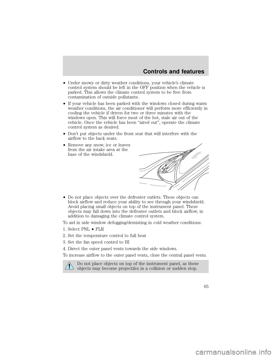
•Remove any snow, ice or leaves
from the air intake area at the
base of the windshield.
•Do not place objects over the defroster outlets. These objects can
block airflow and reduce your ability to see through your windshield.
Avoid placing small objects on top of the instrument panel. These
objects may fall down into the defroster outlets and block airflow, in
addition to damaging the climate control system.
To aid in side window defogging/demisting in cold weather conditions:
1. Select PNL•FLR
2. Set the temperature control to full heat
3. Set the fan speed control to HI
4. Direct the outer panel vents towards the side windows.
To increase airflow to the outer panel vents, close the central panel vents.
Do not place objects on top of the instrument panel, as these
objects may become projectiles in a collision or sudden stop.
Controls and features
65
Page 67 of 280
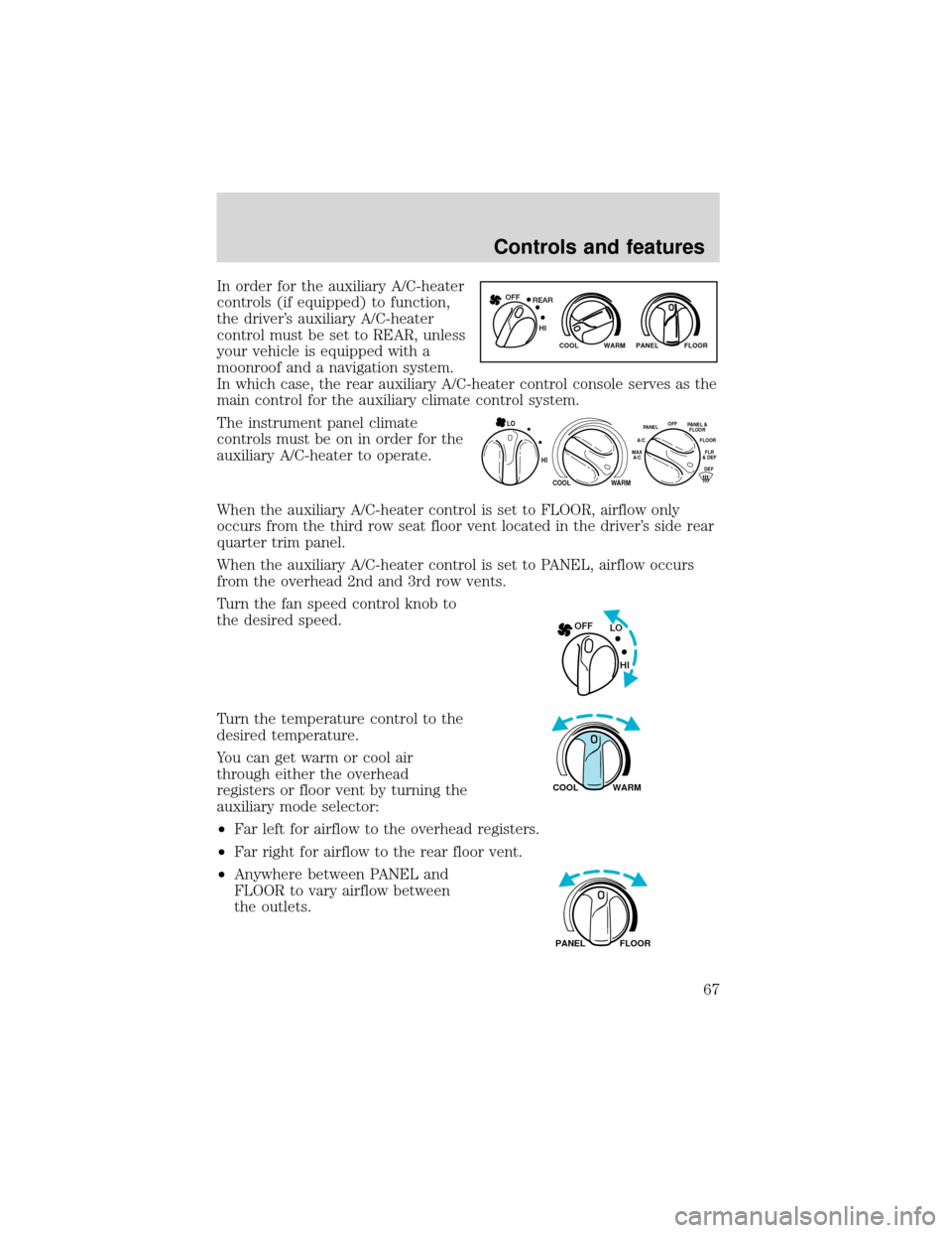
In order for the auxiliary A/C-heater
controls (if equipped) to function,
the driver’s auxiliary A/C-heater
control must be set to REAR, unless
your vehicle is equipped with a
moonroof and a navigation system.
In which case, the rear auxiliary A/C-heater control console serves as the
main control for the auxiliary climate control system.
The instrument panel climate
controls must be on in order for the
auxiliary A/C-heater to operate.
When the auxiliary A/C-heater control is set to FLOOR, airflow only
occurs from the third row seat floor vent located in the driver’s side rear
quarter trim panel.
When the auxiliary A/C-heater control is set to PANEL, airflow occurs
from the overhead 2nd and 3rd row vents.
Turn the fan speed control knob to
the desired speed.
Turn the temperature control to the
desired temperature.
You can get warm or cool air
through either the overhead
registers or floor vent by turning the
auxiliary mode selector:
•Far left for airflow to the overhead registers.
•Far right for airflow to the rear floor vent.
•Anywhere between PANEL and
FLOOR to vary airflow between
the outlets.
WARM PANEL FLOOR COOL
REAR OFF
HI
HI
COOL
WARM
OFFPANELFLOO
R
DEFFLR
& DEF A/C
M
AX
A/CPA
NEL &
FLOOR
LO
LO OFF
HI
WARM COOL
FLOOR PANEL
Controls and features
67
Page 83 of 280
Rear dome lamp
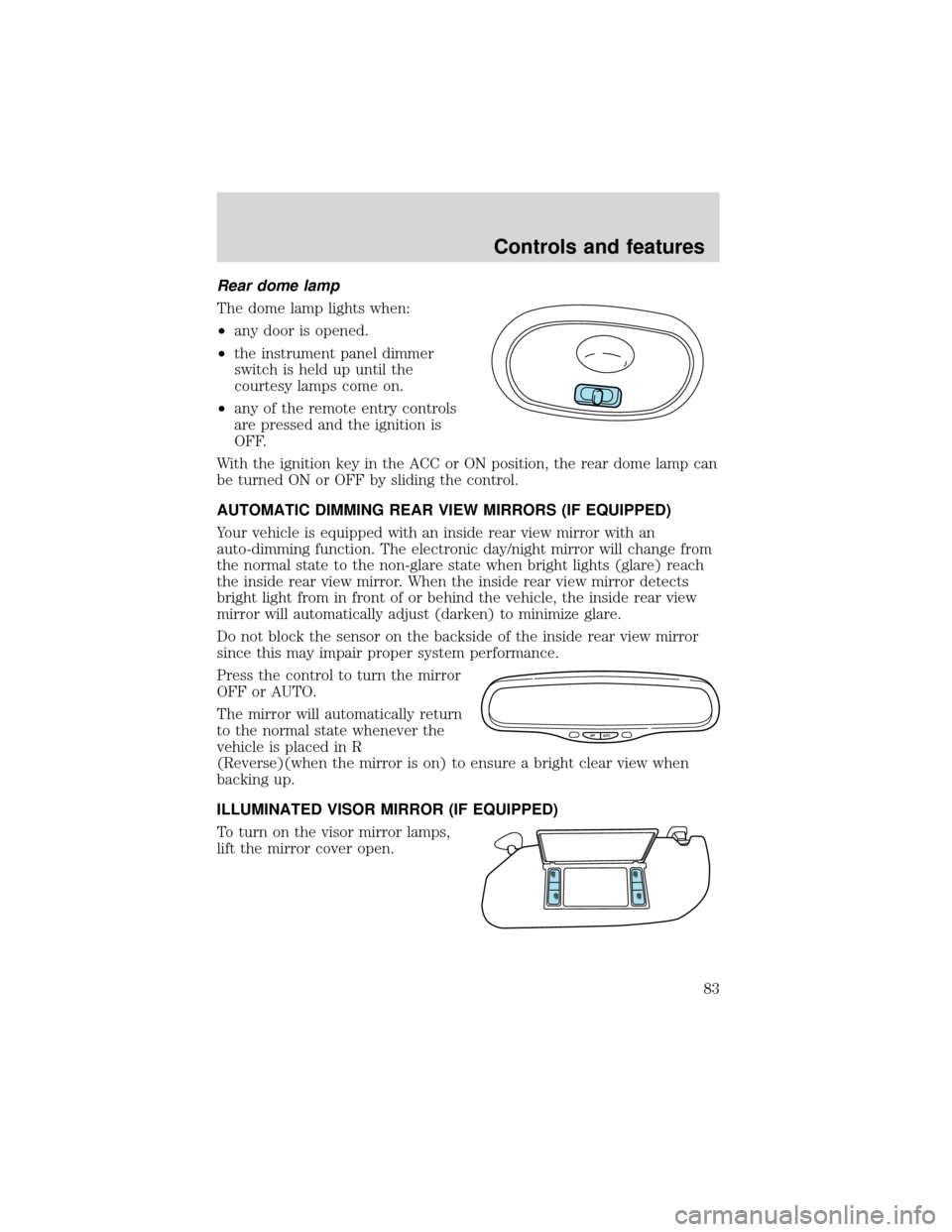
The dome lamp lights when:
•any door is opened.
•the instrument panel dimmer
switch is held up until the
courtesy lamps come on.
•any of the remote entry controls
are pressed and the ignition is
OFF.
With the ignition key in the ACC or ON position, the rear dome lamp can
be turned ON or OFF by sliding the control.
AUTOMATIC DIMMING REAR VIEW MIRRORS (IF EQUIPPED)
Your vehicle is equipped with an inside rear view mirror with an
auto-dimming function. The electronic day/night mirror will change from
the normal state to the non-glare state when bright lights (glare) reach
the inside rear view mirror. When the inside rear view mirror detects
bright light from in front of or behind the vehicle, the inside rear view
mirror will automatically adjust (darken) to minimize glare.
Do not block the sensor on the backside of the inside rear view mirror
since this may impair proper system performance.
Press the control to turn the mirror
OFF or AUTO.
The mirror will automatically return
to the normal state whenever the
vehicle is placed in R
(Reverse)(when the mirror is on) to ensure a bright clear view when
backing up.
ILLUMINATED VISOR MIRROR (IF EQUIPPED)
To turn on the visor mirror lamps,
lift the mirror cover open.
OFF AUTO
Controls and features
83
Page 157 of 280

The air suspension shut-off switch is
located behind an access panel
underneath the passenger side
instrument panel.
On vehicles equipped with
Air Suspension, turn OFF
the Air Suspension switch prior to
jacking, hoisting or towing your
vehicle.
Normal vehicle operation does not
require any action by the driver.
Check air suspension indicator light
The warning and indicator light CK SUSP illuminates when the air
suspension switch is turned off or an air suspension system fault has
been detected.
If the light is illuminated while driving and the air suspension system
switch is not turned off, safely pull off the road at your earliest
convenience. Turn the ignition switch from 4 (On) to 3 (Off) and 4 (On)
again. If the warning light illuminates again, turn the air suspension
switch off and have the vehicle serviced by a dealer or qualified service
technician.
If the vehicle is loaded beyond the recommended maximum payload, the
CK SUSP light may illuminate. To correct this condition, remove or
redistribute the payload according to the recommended requirements
and follow the procedure outlined above.
TRACTION-LOK AXLE (IF EQUIPPED)
This axle provides added traction on slippery surfaces, particularly when
one wheel is on a poor traction surface. Under normal conditions, the
Traction-Lok axle functions like a standard rear axle.
Extended use of other than the manufacturer’s specified size tires on a
Traction-Lok rear axle could result in a permanent reduction in
effectiveness. This loss of effectiveness does not affect normal driving
and should not be noticeable to the driver.
AIR SUSPENSION
SWITCH
INTERRUPTEUR DE
LA SUSPENSION
PNEUMATIQUE
OFF
Driving
157
Page 163 of 280
FOUR-WHEEL DRIVE (4WD) OPERATION (IF EQUIPPED)
For important information regarding safe operation of this type
of vehicle, seePreparing to drive your vehiclein this chapter.
When Four–wheel drive (4WD) is engaged, power is supplied to all four
wheels through a transfer case. 4WD power can be selected when
additional driving power is desired.
If equipped with the Electronic Shift 4WD System, and the
instrument panel control is moved to 4WD Low while the vehicle
is moving, the system will not engage and no damage will occur to
the 4WD system. Before 4WD Low can be engaged, the vehicle
must be at a complete stop with the brake pedal depressed and
the transmission in N (Neutral).
4H or 4L operation is not recommended on dry pavement. Doing
so could result in difficult disengagement of the transfer case,
damage to the transfer case, increased tire wear, decreased fuel
economy and difficulty turning.
CONTROL-TRAC AUTOMATIC FOUR-WHEEL DRIVE SYSTEM
(IF EQUIPPED)
Your 4x4 features the heavy-duty Control-Trac system which includes a
computer-operated transfer case. This unique system is interactive with
the road, continually monitoring and adjusting torque delivery to the
front and rear wheels to optimize vehicle control.
Driving
163
Page 171 of 280
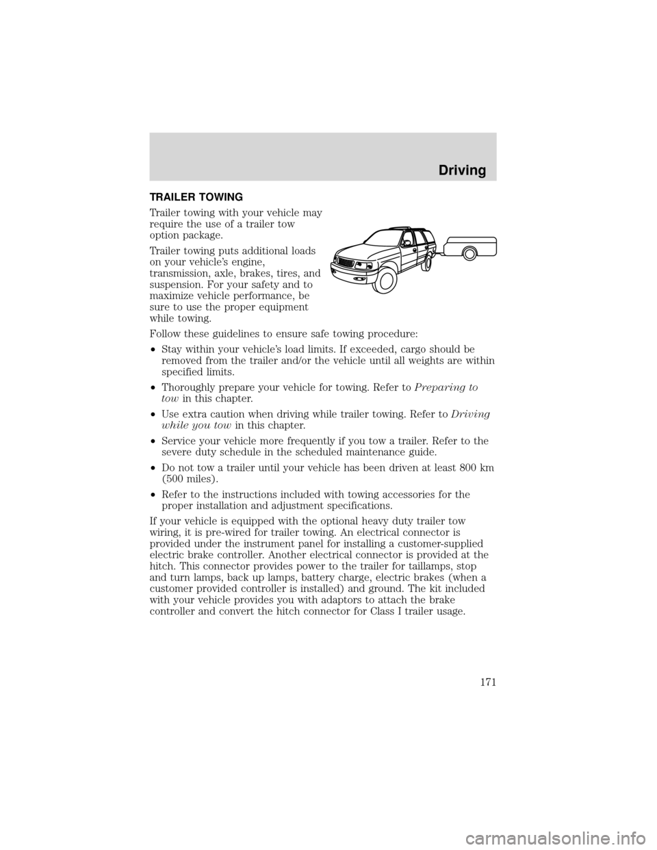
TRAILER TOWING
Trailer towing with your vehicle may
require the use of a trailer tow
option package.
Trailer towing puts additional loads
on your vehicle’s engine,
transmission, axle, brakes, tires, and
suspension. For your safety and to
maximize vehicle performance, be
sure to use the proper equipment
while towing.
Follow these guidelines to ensure safe towing procedure:
•Stay within your vehicle’s load limits. If exceeded, cargo should be
removed from the trailer and/or the vehicle until all weights are within
specified limits.
•Thoroughly prepare your vehicle for towing. Refer toPreparing to
towin this chapter.
•Use extra caution when driving while trailer towing. Refer toDriving
while you towin this chapter.
•Service your vehicle more frequently if you tow a trailer. Refer to the
severe duty schedule in the scheduled maintenance guide.
•Do not tow a trailer until your vehicle has been driven at least 800 km
(500 miles).
•Refer to the instructions included with towing accessories for the
proper installation and adjustment specifications.
If your vehicle is equipped with the optional heavy duty trailer tow
wiring, it is pre-wired for trailer towing. An electrical connector is
provided under the instrument panel for installing a customer-supplied
electric brake controller. Another electrical connector is provided at the
hitch. This connector provides power to the trailer for taillamps, stop
and turn lamps, back up lamps, battery charge, electric brakes (when a
customer provided controller is installed) and ground. The kit included
with your vehicle provides you with adaptors to attach the brake
controller and convert the hitch connector for Class I trailer usage.
Driving
171
Page 184 of 280

Fuse/Relay
LocationFuse Amp
RatingPassenger Compartment Fuse Panel
Description
16 20A Headlamps (Hi Beams), Cluster (Hi Beam
Indicator)
17 10A Heated Mirrors, Heated Grid Switch
Indicator
18 5A Instrument Illumination (Dimmer Switch
Power)
19—Not Used
20 5A Audio, Air Suspension Module, GEM
Module, Memory Module
21 15A Starter Relay, Fuse 20, Transmission
Range Switch
22 10A Air Bag Module, Intelligent Passenger
Airbag Deactivation Module
23 10A Aux A/C, Heated Seats, Trailer Tow
Battery Charge, Turn/Hazard Flasher, 4x4
Clutch Relay, Overhead Console, E/C
Mirror, 4 Wheel Anti-Lock Brake System
(4WABS) Module
24 10A EATC Module, EATC Blower Relay,
Climate Control Switch Assembly, Feeds
Fuse 7
25—Not Used
26 10A Right Side Low Beam Headlamp
27 5A Foglamp Relay and Foglamp Indicator
28 10A Left Side Low Beam Headlamp
29 5A Autolamp Module, Transmission
Overdrive Control Switch
30 30A Passive Anti Theft Transceiver, Cluster,
Ignition Coils, Powertrain Control Module
Relay
31 10A Rear Integrated Control Panel (Audio),
CD Player
Roadside emergencies
184