Page 154 of 248
Roadside coverage beyond basic warranty
In the United States, you may purchase additional roadside assistance
coverage beyond this period through the Ford Auto Club by contacting
your Ford or Lincoln Mercury dealer.
Similarly in Canada, for uninterrupted Roadside Assistance coverage, you
may purchase extended coverage prior to your Basic Warranty's Roadside
Assistance expiring. For more information and enrollment, contact
1±877±294±2582 or visit our website at www.ford.ca.
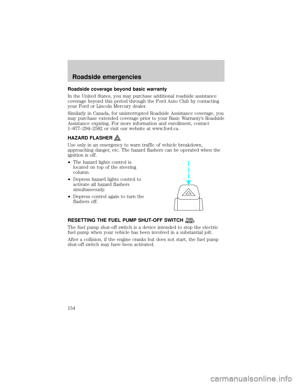
HAZARD FLASHER
Use only in an emergency to warn traffic of vehicle breakdown,
approaching danger, etc. The hazard flashers can be operated when the
ignition is off.
²The hazard lights control is
located on top of the steering
column.
²Depress hazard lights control to
activate all hazard flashers
simultaneously.
²Depress control again to turn the
flashers off.
RESETTING THE FUEL PUMP SHUT-OFF SWITCH
FUEL
RESET
The fuel pump shut-off switch is a device intended to stop the electric
fuel pump when your vehicle has been involved in a substantial jolt.
After a collision, if the engine cranks but does not start, the fuel pump
shut-off switch may have been activated.
Roadside emergencies
154
Page 157 of 248
Passenger compartment fuse panel
The fuse panel is located below and to the left of the steering wheel by
the brake pedal. Remove the panel cover to access the fuses.
To remove a fuse use the fuse puller tool provided on the fuse panel
cover.
The fuses are coded as follows.
Fuse/Relay
LocationFuse Amp
RatingPassenger Compartment Fuse Panel
Description
1 Ð Not Used
2 Ð Not Used
3 Ð Not Used
4 10A Air Bags
5 Ð Not Used
6 15A Instrument Cluster, Warning Lamps
Module, Transmission Control Switch,
Lighting Control Module (LCM)
7 Ð Not Used
27 25
26 2423 21
2219
20
18 16
17 1514 12
131030
32
31
28
29
11
97
8653
41
2
Roadside emergencies
157
Page 158 of 248
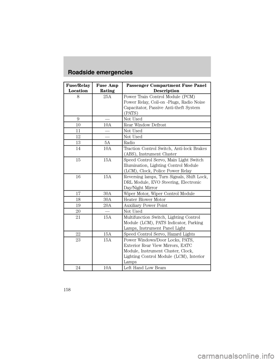
Fuse/Relay
LocationFuse Amp
RatingPassenger Compartment Fuse Panel
Description
8 25A Power Train Control Module (PCM)
Power Relay, Coil-on -Plugs, Radio Noise
Capacitator, Passive Anti-theft System
(PATS)
9 Ð Not Used
10 10A Rear Window Defrost
11 Ð Not Used
12 Ð Not Used
13 5A Radio
14 10A Traction Control Switch, Anti-lock Brakes
(ABS), Instrument Cluster
15 15A Speed Control Servo, Main Light Switch
Illumination, Lighting Control Module
(LCM), Clock, Police Power Relay
16 15A Reversing lamps, Turn Signals, Shift Lock,
DRL Module, EVO Steering, Electronic
Day/Night Mirror
17 30A Wiper Motor, Wiper Control Module
18 30A Heater Blower Motor
19 20A Auxiliary Power Point
20 Ð Not Used
21 15A Multifunction Switch, Lighting Control
Module (LCM), PATS Indicator, Parking
Lamps, Instrument Panel Light
22 15A Speed Control Servo, Hazard Lights
23 15A Power Windows/Door Locks, PATS,
Exterior Rear View Mirrors, EATC
Module, Instrument Cluster, Clock,
Lighting Control Module (LCM), Interior
Lamps
24 10A Left Hand Low Beam
Roadside emergencies
158
Page 161 of 248
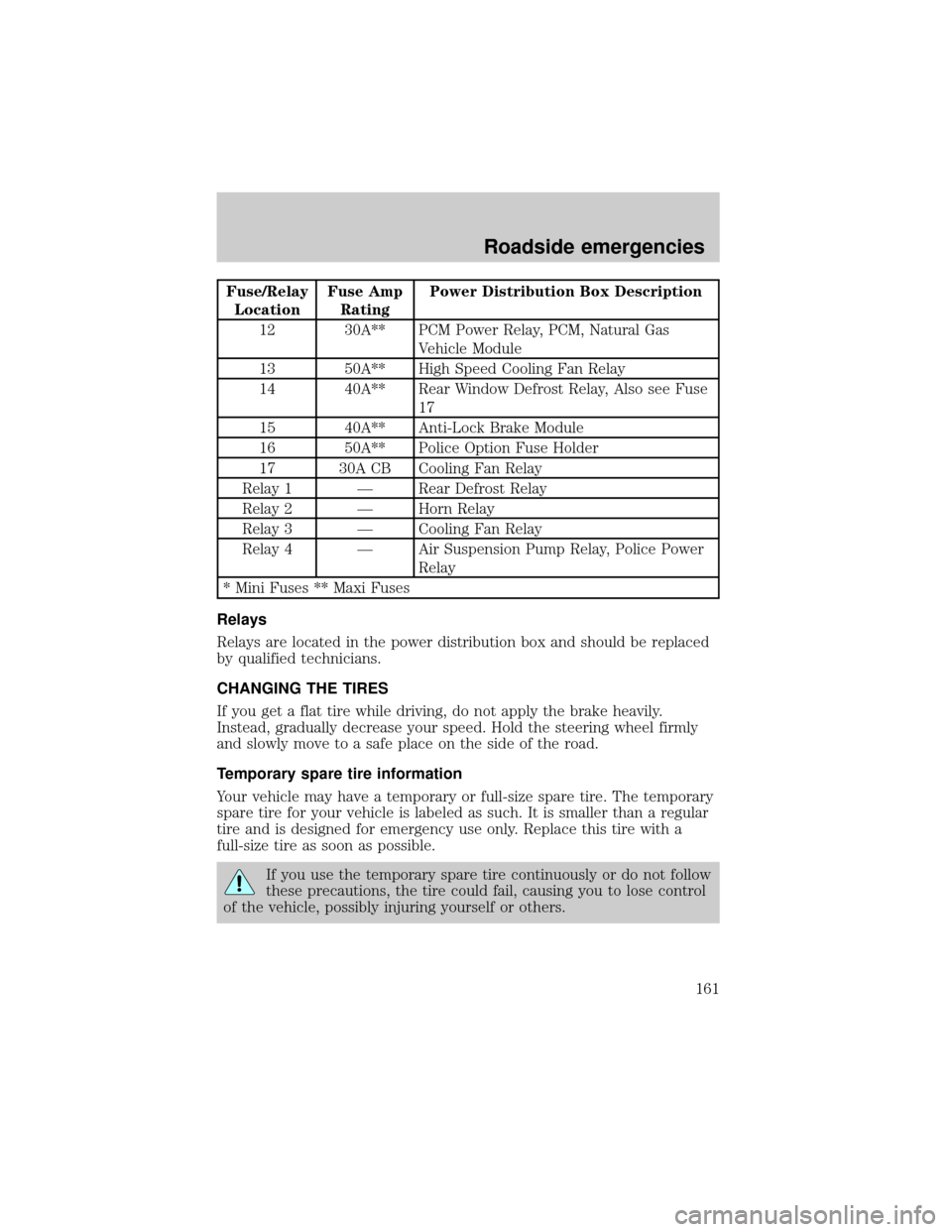
Fuse/Relay
LocationFuse Amp
RatingPower Distribution Box Description
12 30A** PCM Power Relay, PCM, Natural Gas
Vehicle Module
13 50A** High Speed Cooling Fan Relay
14 40A** Rear Window Defrost Relay, Also see Fuse
17
15 40A** Anti-Lock Brake Module
16 50A** Police Option Fuse Holder
17 30A CB Cooling Fan Relay
Relay 1 Ð Rear Defrost Relay
Relay 2 Ð Horn Relay
Relay 3 Ð Cooling Fan Relay
Relay 4 Ð Air Suspension Pump Relay, Police Power
Relay
* Mini Fuses ** Maxi Fuses
Relays
Relays are located in the power distribution box and should be replaced
by qualified technicians.
CHANGING THE TIRES
If you get a flat tire while driving, do not apply the brake heavily.
Instead, gradually decrease your speed. Hold the steering wheel firmly
and slowly move to a safe place on the side of the road.
Temporary spare tire information
Your vehicle may have a temporary or full-size spare tire. The temporary
spare tire for your vehicle is labeled as such. It is smaller than a regular
tire and is designed for emergency use only. Replace this tire with a
full-size tire as soon as possible.
If you use the temporary spare tire continuously or do not follow
these precautions, the tire could fail, causing you to lose control
of the vehicle, possibly injuring yourself or others.
Roadside emergencies
161
Page 174 of 248
IDENTIFYING COMPONENTS IN THE ENGINE COMPARTMENT
4.6L SOHC V8 engine
1. Brake fluid reservoir
2. Engine oil dipstick
3. Engine oil filler cap
4. Windshield washer fluid reservoir
5. Air filter assembly
6. Power steering fluid reservoir
7. Engine coolant reservoir
8. Battery
9. Automatic transmission fluid dipstick
912
3
6578
4
Maintenance and care
174
Page 186 of 248
Continued operation will increase the engine temperature:
²The
symbol will begin to flash.
²If your vehicle is equipped with digital gauges, the gauge bars will
flash and a tone will sound every five seconds for one minute.
²The engine will completely shut down, causing steering and braking
effort to increase.
Once the engine temperature cools, the engine can be re-started. Take
your vehicle to a service facility as soon as possible to minimize engine
damage.
When fail-safe mode is activated
You have limited engine power when in the fail-safe mode, so drive the
vehicle with caution. The vehicle will not be able to maintain high-speed
operation and the engine will run rough. Remember that the engine is
capable of completely shutting down automatically to prevent engine
damage, therefore:
1. Pull off the road as soon as safely possible and turn off the engine.
2. Arrange for the vehicle to be taken to a service facility.
3. If this is not possible, wait a short period for the engine to cool.
4. Check the coolant level and replenish if low.
Never remove the coolant reservoir cap while the engine is
running or hot.
5. Re-start the engine and take your vehicle to a service facility.
Driving the vehicle without repairing the engine problem
increases the chance of engine damage. Take your vehicle to a
service facility as soon as possible.
Maintenance and care
186
Page 187 of 248
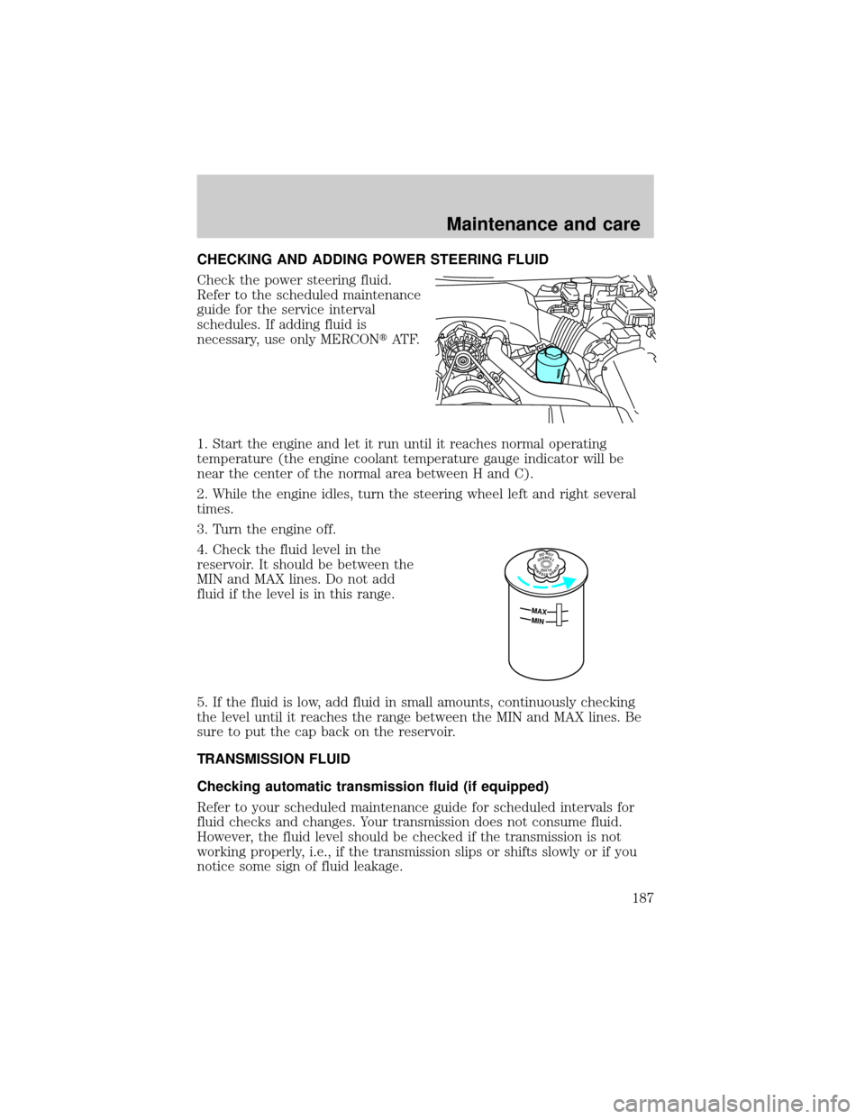
CHECKING AND ADDING POWER STEERING FLUID
Check the power steering fluid.
Refer to the scheduled maintenance
guide for the service interval
schedules. If adding fluid is
necessary, use only MERCONtAT F.
1. Start the engine and let it run until it reaches normal operating
temperature (the engine coolant temperature gauge indicator will be
near the center of the normal area between H and C).
2. While the engine idles, turn the steering wheel left and right several
times.
3. Turn the engine off.
4. Check the fluid level in the
reservoir. It should be between the
MIN and MAX lines. Do not add
fluid if the level is in this range.
5. If the fluid is low, add fluid in small amounts, continuously checking
the level until it reaches the range between the MIN and MAX lines. Be
sure to put the cap back on the reservoir.
TRANSMISSION FLUID
Checking automatic transmission fluid (if equipped)
Refer to your scheduled maintenance guide for scheduled intervals for
fluid checks and changes. Your transmission does not consume fluid.
However, the fluid level should be checked if the transmission is not
working properly, i.e., if the transmission slips or shifts slowly or if you
notice some sign of fluid leakage.
DONOTOVERFILLPOWERSTEERINGFLUID
MAX
MIN
Maintenance and care
187
Page 218 of 248
²Cover the highlighted areas to prevent water damage when cleaning
the engine.
²Never wash or rinse the engine while it is running; water in the
running engine may cause internal damage.
Cleaning the instrument panel
Clean with a damp cloth, then dry with a dry cloth.
Avoid cleaner or polish that increases the gloss of the upper portion of
the instrument panel. The dull finish in this area helps protect the driver
from undesirable windshield reflection.
Do not use chemical solvents or strong detergents when cleaning
the steering wheel or instrument panel to avoid contamination of
the air bag system.
Cleaning the instrument cluster lens
Clean with a damp cloth, then dry with a dry cloth.
Do not use household or glass cleaners as these may damage the lens.
Maintenance and care
218