Page 38 of 248
REAR WINDOW DEFROSTER
The rear defroster control is located
on the instrument panel.
Press the rear defroster control to
clear the rear window of thin ice
and fog.
²A small LED will illuminate when
the rear defroster is activated.
The ignition must be in the ON position to operate the rear window
defroster.
The defroster turns off automatically after 10 minutes or when the
ignition is turned to the OFF position. To manually turn off the defroster
before 10 minutes have passed, push the control again.
USING YOUR AUDIO SYSTEM
AM/FM Stereo
1234AM/FM
SEEKTONE
CLK
TUNE
TONE VOL
12 FMSTDX
VOL
PUSH
ON
Controls and features
38
Page 72 of 248
AUXILIARY POWER POINT
The auxiliary power point is located under the instrument panel on the
left hand side of the front passenger foot well. This outlet should be
used in place of the cigarette lighter for optional electrical accessories.
Power outlets are designed for accessory plugs only. Do not hang
any type of accessory or accessory bracket from the plug.
Improper use of the power outlet can cause damage not covered
by your warranty.
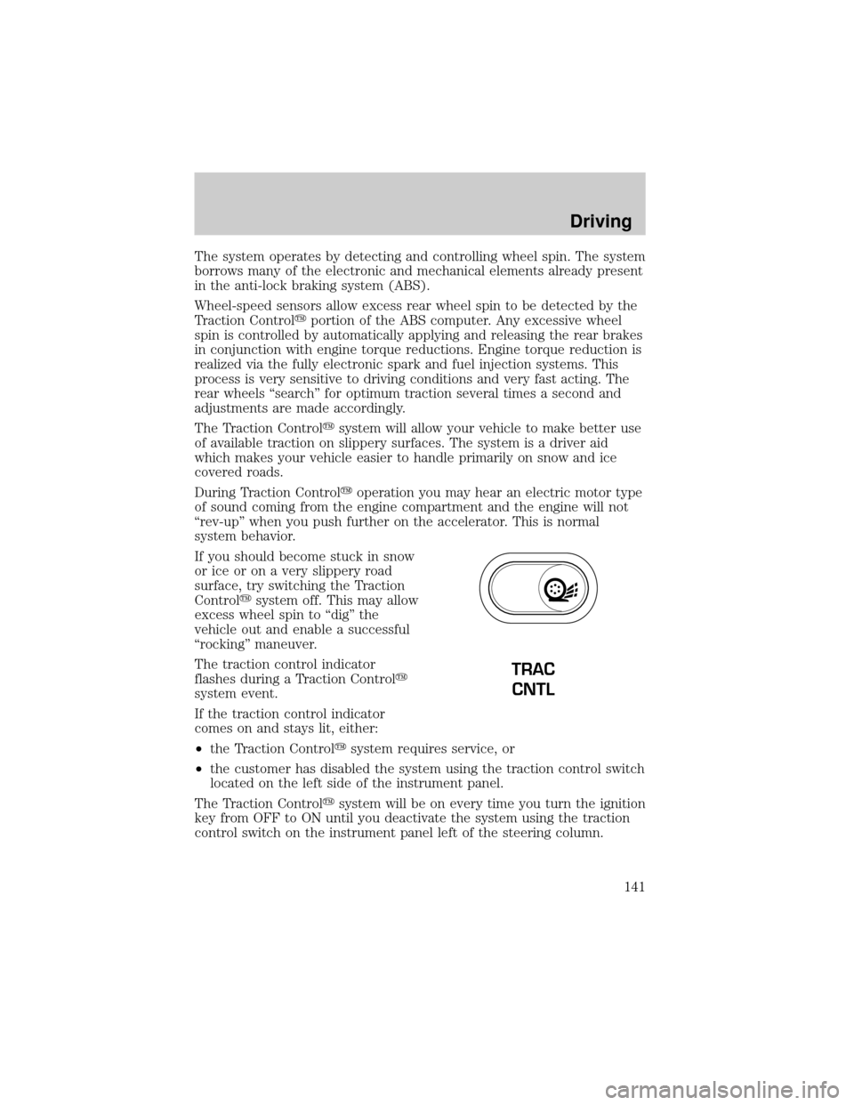
TRACTION CONTROLY(IF EQUIPPED)
This control can be used to turn the
Traction Controlyon or off. Refer
to theTraction Controlysection of
theDrivingchapter for more
information.
TURN SIGNAL CONTROL
²Push down to activate the left
turn signal.
²Push up to activate the right turn
signal.
The flash rate of the turn signal will speed up considerably if the
Lighting Control Module detects a left or right turn lamp bulb (front or
rear) is burned out.
HI
LO
F
S
OFF
Controls and features
72
Page 141 of 248

The system operates by detecting and controlling wheel spin. The system
borrows many of the electronic and mechanical elements already present
in the anti-lock braking system (ABS).
Wheel-speed sensors allow excess rear wheel spin to be detected by the
Traction Controlyportion of the ABS computer. Any excessive wheel
spin is controlled by automatically applying and releasing the rear brakes
in conjunction with engine torque reductions. Engine torque reduction is
realized via the fully electronic spark and fuel injection systems. This
process is very sensitive to driving conditions and very fast acting. The
rear wheels ªsearchº for optimum traction several times a second and
adjustments are made accordingly.
The Traction Controlysystem will allow your vehicle to make better use
of available traction on slippery surfaces. The system is a driver aid
which makes your vehicle easier to handle primarily on snow and ice
covered roads.
During Traction Controlyoperation you may hear an electric motor type
of sound coming from the engine compartment and the engine will not
ªrev-upº when you push further on the accelerator. This is normal
system behavior.
If you should become stuck in snow
or ice or on a very slippery road
surface, try switching the Traction
Controlysystem off. This may allow
excess wheel spin to ªdigº the
vehicle out and enable a successful
ªrockingº maneuver.
The traction control indicator
flashes during a Traction Controly
system event.
If the traction control indicator
comes on and stays lit, either:
²the Traction Controlysystem requires service, or
²the customer has disabled the system using the traction control switch
located on the left side of the instrument panel.
The Traction Controlysystem will be on every time you turn the ignition
key from OFF to ON until you deactivate the system using the traction
control switch on the instrument panel left of the steering column.
TRAC
CNTL
Driving
141
Page 157 of 248
Passenger compartment fuse panel
The fuse panel is located below and to the left of the steering wheel by
the brake pedal. Remove the panel cover to access the fuses.
To remove a fuse use the fuse puller tool provided on the fuse panel
cover.
The fuses are coded as follows.
Fuse/Relay
LocationFuse Amp
RatingPassenger Compartment Fuse Panel
Description
1 Ð Not Used
2 Ð Not Used
3 Ð Not Used
4 10A Air Bags
5 Ð Not Used
6 15A Instrument Cluster, Warning Lamps
Module, Transmission Control Switch,
Lighting Control Module (LCM)
7 Ð Not Used
27 25
26 2423 21
2219
20
18 16
17 1514 12
131030
32
31
28
29
11
97
8653
41
2
Roadside emergencies
157
Page 158 of 248

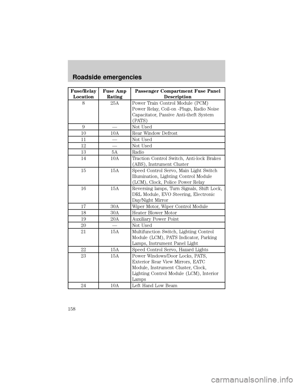
Fuse/Relay
LocationFuse Amp
RatingPassenger Compartment Fuse Panel
Description
8 25A Power Train Control Module (PCM)
Power Relay, Coil-on -Plugs, Radio Noise
Capacitator, Passive Anti-theft System
(PATS)
9 Ð Not Used
10 10A Rear Window Defrost
11 Ð Not Used
12 Ð Not Used
13 5A Radio
14 10A Traction Control Switch, Anti-lock Brakes
(ABS), Instrument Cluster
15 15A Speed Control Servo, Main Light Switch
Illumination, Lighting Control Module
(LCM), Clock, Police Power Relay
16 15A Reversing lamps, Turn Signals, Shift Lock,
DRL Module, EVO Steering, Electronic
Day/Night Mirror
17 30A Wiper Motor, Wiper Control Module
18 30A Heater Blower Motor
19 20A Auxiliary Power Point
20 Ð Not Used
21 15A Multifunction Switch, Lighting Control
Module (LCM), PATS Indicator, Parking
Lamps, Instrument Panel Light
22 15A Speed Control Servo, Hazard Lights
23 15A Power Windows/Door Locks, PATS,
Exterior Rear View Mirrors, EATC
Module, Instrument Cluster, Clock,
Lighting Control Module (LCM), Interior
Lamps
24 10A Left Hand Low Beam
Roadside emergencies
158
Page 173 of 248
Working with the engine off
1. Set the parking brake and ensure the gearshift is securely latched in P
(Park).
2. Turn off the engine and remove the key.
3. Block the wheels to prevent the vehicle from moving unexpectedly.
Working with the engine on
1. Set the parking brake and ensure the gearshift is securely latched in P
(Park).
2. Block the wheels to prevent the vehicle from moving unexpectedly.
NOTE:Do not start your engine with the air cleaner removed and do
not remove it while the engine is running.
OPENING THE HOOD
1. Inside the vehicle, pull the hood
release handle located under the
instrument panel.
2. Go to the front of the vehicle and
release the auxiliary latch that is
located under the front of the hood.
3. Lift the hood until the lift
cylinders hold it open.
Maintenance and care
173
Page 214 of 248

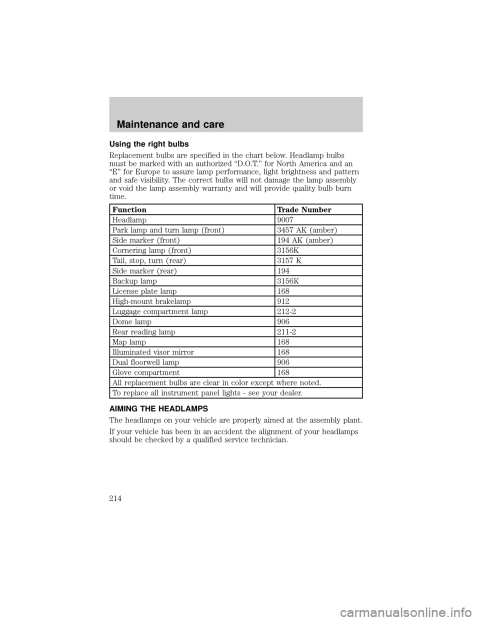
Using the right bulbs
Replacement bulbs are specified in the chart below. Headlamp bulbs
must be marked with an authorized ªD.O.T.º for North America and an
ªEº for Europe to assure lamp performance, light brightness and pattern
and safe visibility. The correct bulbs will not damage the lamp assembly
or void the lamp assembly warranty and will provide quality bulb burn
time.
Function Trade Number
Headlamp 9007
Park lamp and turn lamp (front) 3457 AK (amber)
Side marker (front) 194 AK (amber)
Cornering lamp (front) 3156K
Tail, stop, turn (rear) 3157 K
Side marker (rear) 194
Backup lamp 3156K
License plate lamp 168
High-mount brakelamp 912
Luggage compartment lamp 212-2
Dome lamp 906
Rear reading lamp 211-2
Map lamp 168
Illuminated visor mirror 168
Dual floorwell lamp 906
Glove compartment 168
All replacement bulbs are clear in color except where noted.
To replace all instrument panel lights - see your dealer.
AIMING THE HEADLAMPS
The headlamps on your vehicle are properly aimed at the assembly plant.
If your vehicle has been in an accident the alignment of your headlamps
should be checked by a qualified service technician.
Maintenance and care
214
Page 218 of 248
²Cover the highlighted areas to prevent water damage when cleaning
the engine.
²Never wash or rinse the engine while it is running; water in the
running engine may cause internal damage.
Cleaning the instrument panel
Clean with a damp cloth, then dry with a dry cloth.
Avoid cleaner or polish that increases the gloss of the upper portion of
the instrument panel. The dull finish in this area helps protect the driver
from undesirable windshield reflection.
Do not use chemical solvents or strong detergents when cleaning
the steering wheel or instrument panel to avoid contamination of
the air bag system.
Cleaning the instrument cluster lens
Clean with a damp cloth, then dry with a dry cloth.
Do not use household or glass cleaners as these may damage the lens.
Maintenance and care
218