Page 52 of 330

Marea Weekend Technical Data
2000 range o Rear suspension
00.44
Rear suspension independent with track control arms anchored to an auxiliary crossmember. Variable
flexibility coil springs and anti-roll bar. Gas shock absorbers with low friction coefficient lower bushes.
ENGINE TYPE
Coil springs
Wire diameter mm 12.3±0.1 12.8±0.1
Number of effective coils 5.93 5.93
Coil direction clockwise
Released spring height mm 320 322
419-445 daN mm
Spring height under
184 -
a load of:
432 daN mm -184
Spring are divided into two categories,
identified by markings
412 daN
yellow (1) for those: oT mm
>184 _
under a load of hpinht
432 daN a
of mm
->184
412 daN aJS* green (1) for those ot mm
<184 -
under a load of: _ hpiflht 432 daN a "eif£J ot mm -<184
(1) Springs of the same type must be fitted.
Dampers
Make double acting, telesopic, gas
Open (start of damping action) mm 321 ± 2
Closed (iron against iron) mm 224 ± 2
Stroke mm 97
Anti-roll bar
Anti-roll bar diameter mm 17
Copyright by Fiat A uto 45
Page 60 of 330
Marengo^™ Introduction and technical data
2000 range Index
oo.
page
INTRODUCTION
- Identification data 1
- Dimensions 1
- Weights 2
- Performance 2
- Fuel consumption 2
TECHNICAL DATA
- Front suspension 3
- Rear suspension 3
NOTE
This section gives technical data for the Fiat Marengo 2000 range equipped with a 1910 JTD EC F3 en
gine. For further information, see the Fiat Marea - Fiat Marea Weekend manual publication no. 506.763
and subsequent updates
Copyright by Fiat Auto
Page 63 of 330
Marengo 0 ™ Technical Data
2000 range Suspension and wheels
OO.o
Rear suspension independent with track control arms anchored to an auxiliary crossmember. Variable
rate coil springs and antiroll bar. Gas shock absorbers with low friction coefficient lower bushes.
ENGINE TYPE
Coil springs
Diameter of wire mm 13.9 ± 0.1
Number of coils 5.93
Direction of coil clockwise
Height of spring released mm 323
Height under 424 ± 456 daN mm a load of : 207
The springs are divided into two categories,
identifiable by a mark:
XX°l 440 daN having a heigh, of i -i x mm load of:
> 207
green (1) for having a height of those under a 440 daN a a i J x. mm load of:
^ 207
(1) When fitting, match springs of the same type.
Shock absorbers
Make double acting, telesopic, gas
Open (start of damping action) mm 321 ± 2
Closed (metal against metal) mm 224 ± 2
Travel mm 97
Anti-roll bar
Anti-roll bar diameter mm 19
FRONT SUSPENSION
Anti-roll bar
Anti-roll bar diameter mm 18
Copyright by Fiat Auto 3
Page 68 of 330
Marea- Marea Weekend • *» Engine
2000 range (§) Fuel feed system
10.
Pages
FUEL FEED SYSTEM
- Engine management system 1
- Diagram showing engine exhaust assem
bly 1
- Fuel anti-evaporation system ~2
- Location of diagnostic socket 2
- Location of injection/ignition system
components in the engine compartment 3
- Front Lambda sensor . 4
- Rear Lambda sensor 4
- Catalytic converter heat shield 5
- Catalytic converter 5
- Exhaust manifold 6
- Electric fuel pump with level sender unit 7
Copyright by Fiat Auto
Page 69 of 330

Marea- Marea Weekend • ^ Engine
2000 range (Q) Fuel feed system
10.
ENGINE MANAGEMENT SYSTEM
The Marea-Marea Weekend 1596 16v has a 4 cylinder in line engine, with 16 valves, 1596 cc, twin over
head camshaft and a Marelli IAW 4EF integrated electronic injection/ignition system.
The fuel system differs from the one described for the 1581 16v "99 range" version through the addition
of several variants to make it compatible with the EEC Stage 3 EOBD regulations.
The main modifications to the system can be summarized as follows:
- Engine management control unit with IAW 4EF
- Catalytic converter near the exhaust manifold to take maximum advantage of the heat of the gases.
- Two Lambda senors, one upstream (front) and one downstream (rear) which check the quality of the
exhaust gases and the operation of the catalyzer.
- Adoption of a timing sensor on the inlet side timing pulley.
DIAGRAM SHOWING ENGINE EXHAUST ASSEMBLY
1. Exhaust manifold
2. Catalytic converter
3. Front Lambda sensor
4. Rear Lambda sensor
5. Silencers
Copyright by Fiat Auto 1
Page 72 of 330

Engine
Fuel feed system
Marea- Marea Weekend •
2000 range @
FRONT LAMBDA SENSOR
Removing
- Disconnect the negative battery terminal.
1. Disconect the electrical conection (1a), re
lease the wiring from the retaining band
(2) and disconnect the Lambda sensor (3).
Refitting
- Position the sensor and tighten it to torque
avoiding forcing the component which
would damage it irreparably.
Apply special grease (e.g. Bosch 5
964080112) to the threaded part of the
sensor.
REAR LAMBDA SENSOR
Removing
- Position the vehicle on a lift.
- Disconnect the negative battery terminal.
2. Disconnect the electrical connection (1)
and release the wiring from the retaining
bands.
3. Raise the vehicle and disconnect the
Lambda sensor.
Refitting
- Position the sensor and tighten it to torque
avoiding force on the component which
would damage it irreparably.
Apply special grease (e.g. Bosch 5
964080112) to the threaded part of the
sensor.
- Connect the connector and renew the
Lambda senor cable fastenings.
4 Print n° 506.763/23
Page 74 of 330
Engine
Fuel feed system
16v Marea- Marea Weekend ©
2000 range @
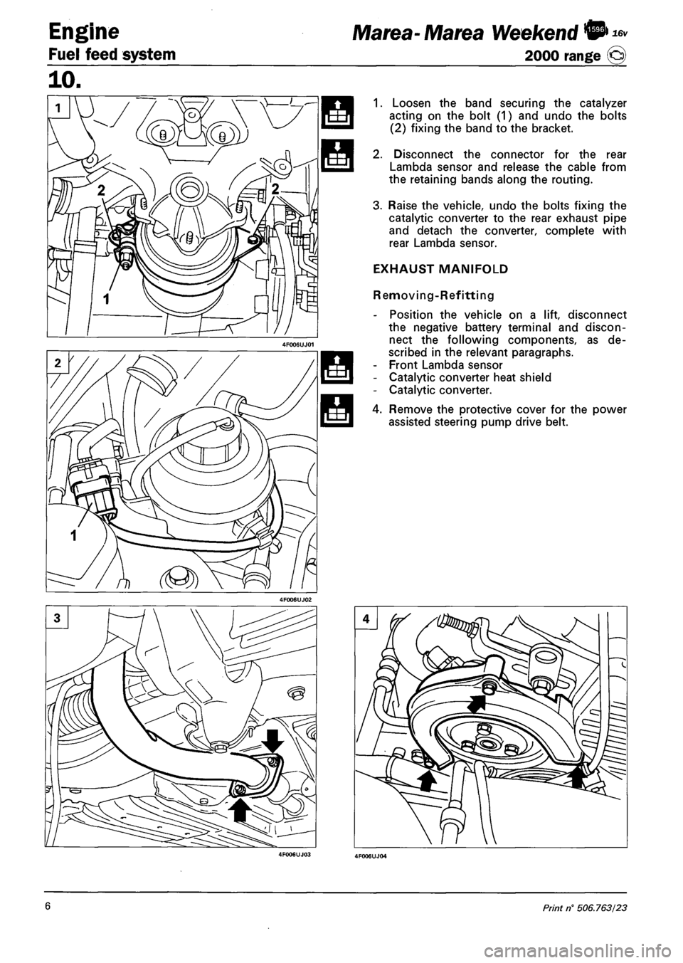
1. Loosen the band securing the catalyzer
acting on the bolt (1) and undo the bolts
(2) fixing the band to the bracket.
2. Disconnect the connector for the rear
Lambda sensor and release the cable from
the retaining bands along the routing.
3. Raise the vehicle, undo the bolts fixing the
catalytic converter to the rear exhaust pipe
and detach the converter, complete with
rear Lambda sensor.
EXHAUST MANIFOLD
Removing-Refitting
- Position the vehicle on a lift, disconnect
the negative battery terminal and discon
nect the following components, as de
scribed in the relevant paragraphs.
- Front Lambda sensor
- Catalytic converter heat shield
- Catalytic converter.
4. Remove the protective cover for the power
assisted steering pump drive belt.
6 Print n° 506.763/23
Page 77 of 330
Marea- MareaWeekend • ** Engine
2000 range @ . . Index
10.
. Page
FUEL FEED SYSTEM
- Engine management system 1
- Location of injection/ignition system
components 2
- Location of diagnostic socket 2
- Removing-refitting accelorometer 3
- Removing-refitting front Lambda sensor 3
- Removing-refitting rear Lambda sensor 4
- Removing-refitting heat shield 5
- Removing-refitting catalytic converter 7
Copyright by Fiat Auto