2001 DODGE TOWN AND COUNTRY check oil
[x] Cancel search: check oilPage 423 of 2321
Spiral plate technology is the process by which the
plates holding the active material in the battery are
wound tightly in coils instead of hanging flat, like
conventional batteries. This design has a lower inter-
nal resistance and also increases the active material
surface area.
WARNING: NEVER EXCEED 14.4 VOLTS WHEN
CHARGING A SPIRAL PLATE BATTERY. PERSONAL
INJURY AND/OR BATTERY DAMAGE MAY RESULT.
Due to the maintanance-free design, distilled water
cannot be added to this battery. Therefore, if more
than 14.4 volts are used during the spiral plate bat-
tery charging process, water vapor can be exhausted
through the pressure-sensitive battery vents and lost
for good. This can permanently damage the spiral
plate battery. Never exceed 14.4 volts when charging
a spiral plate battery. Personal injury and/or battery
damage may result.
CONVENTIONAL BATTERY - GASOLINE ENGINE
Low-maintenance conventional batteries are used
on vehicles equipped with a gasoline engine, these
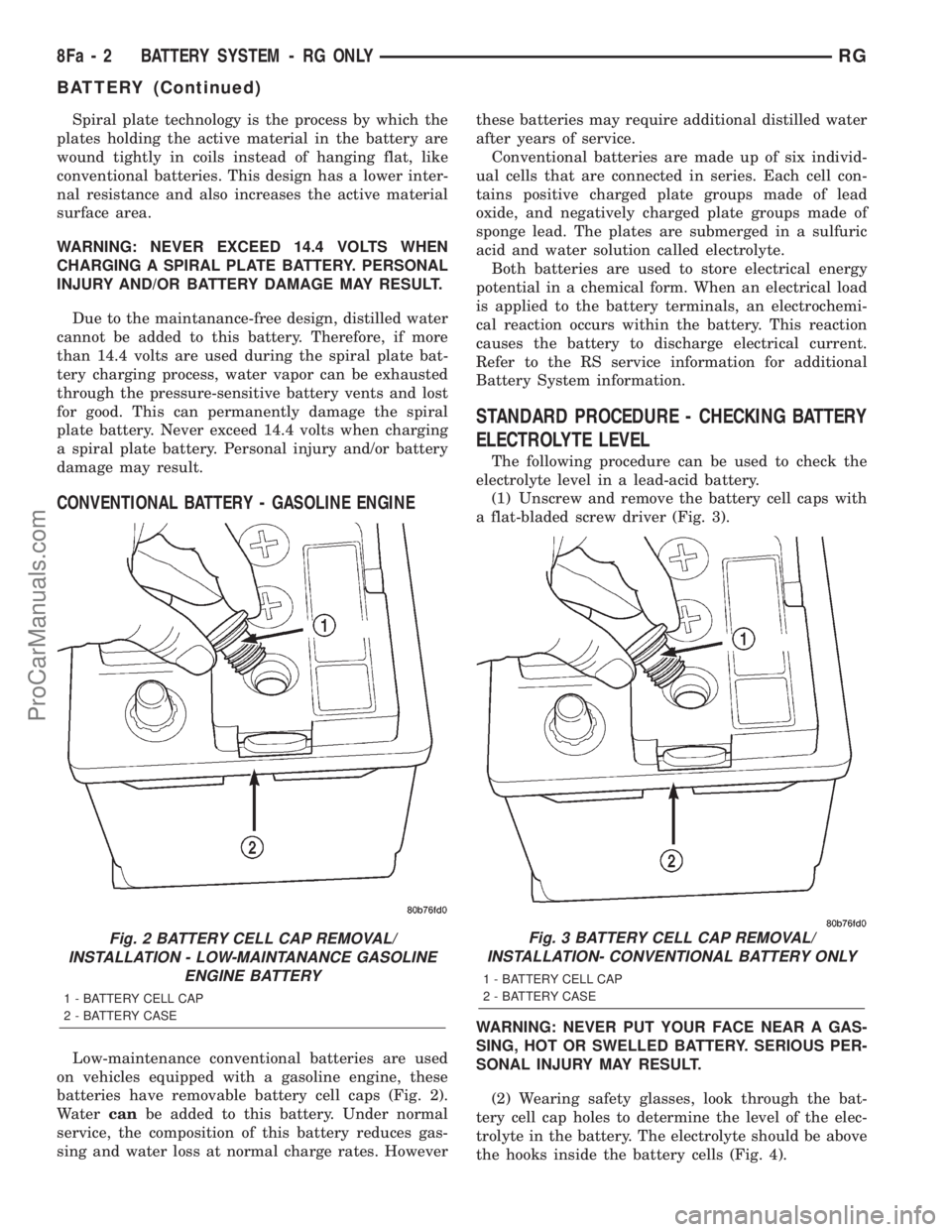
batteries have removable battery cell caps (Fig. 2).
Watercanbe added to this battery. Under normal
service, the composition of this battery reduces gas-
sing and water loss at normal charge rates. Howeverthese batteries may require additional distilled water
after years of service.
Conventional batteries are made up of six individ-
ual cells that are connected in series. Each cell con-
tains positive charged plate groups made of lead
oxide, and negatively charged plate groups made of
sponge lead. The plates are submerged in a sulfuric
acid and water solution called electrolyte.
Both batteries are used to store electrical energy
potential in a chemical form. When an electrical load
is applied to the battery terminals, an electrochemi-
cal reaction occurs within the battery. This reaction
causes the battery to discharge electrical current.
Refer to the RS service information for additional
Battery System information.
STANDARD PROCEDURE - CHECKING BATTERY
ELECTROLYTE LEVEL
The following procedure can be used to check the
electrolyte level in a lead-acid battery.
(1) Unscrew and remove the battery cell caps with
a flat-bladed screw driver (Fig. 3).
WARNING: NEVER PUT YOUR FACE NEAR A GAS-
SING, HOT OR SWELLED BATTERY. SERIOUS PER-
SONAL INJURY MAY RESULT.
(2) Wearing safety glasses, look through the bat-
tery cell cap holes to determine the level of the elec-
trolyte in the battery. The electrolyte should be above
the hooks inside the battery cells (Fig. 4).
Fig. 2 BATTERY CELL CAP REMOVAL/
INSTALLATION - LOW-MAINTANANCE GASOLINE
ENGINE BATTERY
1 - BATTERY CELL CAP
2 - BATTERY CASE
Fig. 3 BATTERY CELL CAP REMOVAL/
INSTALLATION- CONVENTIONAL BATTERY ONLY
1 - BATTERY CELL CAP
2 - BATTERY CASE
8Fa - 2 BATTERY SYSTEM - RG ONLYRG
BATTERY (Continued)
ProCarManuals.com
Page 452 of 2321

AUTO SHUT DOWN RELAY
DESCRIPTION
The relay is located in the Power Distribution Cen-
ter (PDC). For the location of the relay within the
PDC, refer to the PDC cover for location. Check elec-
trical terminals for corrosion and repair as necessary
OPERATION
The ASD sense circuit informs the PCM when the
ASD relay energizes. A 12 volt signal at this input
indicates to the PCM that the ASD has been acti-
vated. This input is used only to sense that the ASD
relay is energized.
When energized, the ASD relay supplies battery
voltage to the fuel injectors, ignition coils and the
heating element in each oxygen sensor. If the PCM
does not receive 12 volts from this input after
grounding the ASD relay, it sets a Diagnostic Trouble
Code (DTC).
When energized, the ASD relay provides power to
operate the injectors, ignition coil, generator field, O2
sensor heaters (both upstream and downstream), and
also provides a sense circuit to the PCM for diagnos-
tic purposes. The PCM energizes the ASD any time
there is a Crankshaft Position sensor signal that
exceeds a predetermined value. The ASD relay can
also be energized after the engine has been turned
off to perform an O2 sensor heater test, if vehicle is
equipped with OBD II diagnostics.
As mentioned earlier, the PCM energizes the ASD
relay during an O2 sensor heater test. This test is
performed only after the engine has been shut off.
The PCM still operates internally to perform several
checks, including monitoring the O2 sensor heaters.
CAMSHAFT POSITION
SENSOR
DESCRIPTION
The camshaft position sensorfor the 3.3/3.8L is
mounted in the front of the timing case cover (Fig. 7)
and the camshaft position sensor for the 2.4L is
mounted on the end of the cylinder head (Fig. 4).
OPERATION
The camshaft position sensor provides cylinder
identification to the Powertrain Control Module
(PCM) (Fig. 2). The sensor generates pulses as
groups of notches on the camshaft sprocket pass
underneath it (Fig. 3). The PCM keeps track of
crankshaft rotation and identifies each cylinder by
the pulses generated by the notches on the camshaftsprocket. Four crankshaft pulses follow each group of
camshaft pulses.
When the PCM receives 2 cam pulses followed by
the long flat spot on the camshaft sprocket, it knows
that the crankshaft timing marks for cylinder 1 are
next (on driveplate). When the PCM receives one
camshaft pulse after the long flat spot on the
sprocket, cylinder number 2 crankshaft timing marks
are next. After 3 camshaft pulses, the PCM knows
cylinder 4 crankshaft timing marks follow. One cam-
shaft pulse after the 3 pulses indicates cylinder 5.
The 2 camshaft pulses after cylinder 5 signals cylin-
der 6 (Fig. 3). The PCM can synchronize on cylinders
1or4.
When metal aligns with the sensor, voltage goes
low (less than 0.3 volts). When a notch aligns with
the sensor, voltage switches high (5.0 volts). As a
group of notches pass under the sensor, the voltage
switches from low (metal) to high (notch) then back
to low. The number of notches determine the amount
of pulses. If available, an oscilloscope can display the
square wave patterns of each timing event.
Top Dead Center (TDC) does not occur when
notches on the camshaft sprocket pass below the cyl-
inder. TDC occurs after the camshaft pulse (or
pulses) and after the 4 crankshaft pulses associated
with the particular cylinder. The arrows and cylinder
call outs on Figure 4 represent which cylinder the
flat spot and notches identify, they do not indicate
TDC position.
REMOVAL - 2.4L
The camshaft position sensor is mounted to the
rear of the cylinder head.
(1) Remove the negative battery cable.
Fig. 2 Camshaft Position Sensor
1 - ELECTRICAL CONNECTOR
2 - O-RING
3 - PAPER SPACER
RSIGNITION CONTROL8I-3
ProCarManuals.com
Page 458 of 2321

CAUTION: Cleaning of the platinum plug may dam-
age the platinum tip.
REMOVAL
When replacing the spark plugs and spark plug
cables, route the cables correctly and secure them in
the appropriate retainers. Failure to route the cables
properly can cause the radio to reproduce ignition
noise, cross ignition of the spark plugs orshort cir-
cuit the cables to ground.
Always remove cables by grasping at the boot,
rotating the boot 1/2 turn, and pulling straight back
in a steady motion.
(1) Prior to removing the spark plug, spray com-
pressed air around the spark plug hole and the area
around the spark plug.
(2) Remove the spark plug using a quality socket
with a foam insert.
(3) Inspect the spark plug condition.
INSTALLATION
When replacing the spark plugs and spark plug
cables, route the cables correctly and secure them in
the appropriate retainers. Failure to route the cables
properly can cause the radio to reproduce ignition
noise, cross ignition of the spark plugs orshort cir-
cuit the cables to ground.(1) To avoid cross threading, start the spark plug
into the cylinder head by hand.
(2) Tighten spark plugs to 17.5 N´m (13 ft. lbs.)
torque.
(3) Install spark plug cables over spark plugs. A
click will be heard and felt when the cable properly
attaches to the spark plug.
SPARK PLUG CABLE
DESCRIPTION
Spark Plug cables are sometimes referred to as
secondary ignition wires. The wires transfer electri-
cal current from the ignition coil pack to individual
spark plugs at each cylinder. The resistive spark plug
cables are of nonmetallic construction. The cables
provide suppression of radio frequency emissions
from the ignition system.
Check the spark plug cable connections for good
contact at the coil, and spark plugs. Terminals should
be fully seated. The insulators should be in good con-
dition and should fit tightly on the coil, and spark
plugs. Spark plug cables with insulators that are
cracked or torn must be replaced.
Clean Spark Plug cables with a cloth moistened
with a non-flammable solvent. Wipe the cables dry.
Check for brittle or cracked insulation. The spark
plug cables and spark plug boots are made from high
temperature silicone materials. All spark plug cable
leads are properly identified with cylinder numbers.
The inside of most the spark plug boot is coated with
a special high temperature silicone grease for greater
sealing and to minimize boot bonding to the spark
plug insulator.
REMOVAL
Failure to route the cables properly could cause the
radio to reproduce ignition noise, cross ignition of the
spark plugs or short circuit the cables to ground.
Remove spark plug cable from coil first.
Always remove the spark plug cable by grasping
the top of the spark plug insulator, turning the boot
1/2 turn and pulling straight up in a steady motion.
INSTALLATION
Failure to route the cables properly could cause the
radio to reproduce ignition noise, cross ignition of the
spark plugs or short circuit the cables to ground.
Install spark plug insulators over spark plugs.
Ensure the top of the spark plug insulator covers the
upper end of the spark plug tube.Then connect the
other end to coil pack.
Fig. 15 Setting Spark Plug Electrode Gap
1 - TAPER GAUGE
RSIGNITION CONTROL8I-9
SPARK PLUG (Continued)
ProCarManuals.com
Page 476 of 2321
DAYTIME RUNNING LAMPS
Power is reduced using pulse-width modulation to
the high beams, where by the power is switched on
and off rapidly instead of remaining on continuously.
The duration and interval of the power pulses is pro-
grammed into the Front Control Module (FCM).
HEADLAMP SYSTEM
The headlamp system will default to headlamps
ON position when ignition switch is ON and when an
open or short circuit failure occurs on the headlamp
switch input. The system will return to normal oper-
ation when the open or short is repaired. A fault will
be reported by the BCM when a failure occurs on the
dimmer or headlamp switch input.
If the exterior lamps are ON and the headlamp
switch is in any position other than OFF or AUTO
and with the ignition switch OFF (LOCK) after 3
minutes the BCM sends a message via J1850 to the
FCM informing the FCM to turn off the headlamps,
park lamps and fog lamps. This feature prevents the
vehicle battery from being discharged when the vehi-
cle lights have been left ON.
HEADLAMP TIME DELAY SYSTEM
The headlamp time delay system is activated by
turning the headlamps ON (high or low beam) while
the engine is running, turning the ignition switch
OFF, and then turning the headlamp switch OFF
within 45 seconds. The system will not activate if
more than 45 seconds elapse between ignition switch
OFF and headlamp switch OFF. The BCM will allow
the headlamps to remain ON for 90 seconds (config-
urable) before they automatically turn off (If the key
is in the ignition during the headlamp time delay
mode, then both the headlamps and park lamps
(including panel dimming) will be ON). Refer to the
Owner's Manual for more information.
If the headlamp switch is in the Auto Headlamp
Position, the headlamps are ON due to the night sig-
nal from the CMTC and the ignition switch is in any
position other than run/start, the BCM shall enter a
90 second (configurable) Auto Headlamps time delay
mode. If the key is in the ignition during the head-
lamp time delay mode, then both the headlamps and
park lamps (including panel dimming) will be ON. If
the key is not in the ignition, then only the head-
lamps will be ON. The BCM will allow the head-
lamps to remain ON for 90 seconds before they
automatically turn OFF. Refer to the Owner's Man-
ual for more information.
LAMP OUTAGE
If one or more of the following lamps (Low and/or
High beams) are out, then a ªlamps outº indicator
located in the cluster will illuminate.
OPTICAL HORN/HIGH BEAMS
When the multifunction switch is pulled to the first
detent (optical horn) signal, the headlamps are ON,
key-in the ignition the BCM shall send a message via
J1850 to the FCM to turn on the headlamps drivers
to illuminate all four filaments (Low and High
beams). When the multifunction switch is pulled to
the second detent (high beam) signal and the head-
lamps are ON, the BCM shall send a message via
J1850 to the FCM to turn on the headlamps drivers.
The High Beams are illuminated and the Low Beams
and Fog Lamps (if ON) are extinguished. If the head-
lamps were in the high beam configuration when
power was removed from the headlamps, the head-
lamps will be configured as low beam the next time
they are activated.
DIAGNOSIS AND TESTING
WARNING: EYE PROTECTION SHOULD BE USED
WHEN SERVICING GLASS COMPONENTS. PER-
SONAL INJURY CAN RESULT.
CAUTION: Do not touch the glass of halogen bulbs
with fingers or other possibly oily surface, reduced
bulb life will result. Do not use bulbs other than
those indicated in the Bulb Application table. Dam-
age to lamp and/or Daytime Running Lamp Module
can result. Do not use fuses, circuit breakers or
relays having greater amperage value than indi-
cated on the fuse panel or in the Owners Manual.
When a vehicle experiences problems with the
headlamp system, verify the condition of the battery
connections, fuses, charging system, headlamp bulbs,
wire connectors, relay, high beam switch, dimmer
switch, and headlamp switch. Refer to the appropri-
ate wiring information. The wiring information
includes wiring diagrams, proper wire and connector
repair procedures, details of wire harness routing
and retention, connector pin-out information and
location views for the various wire harness connec-
tors, splices and grounds.
Each vehicle is equipped with various lamp assem-
blies. A good ground is necessary for proper lighting
operation. Grounding is provided by the lamp socket
when it comes in contact with the metal body, or
through a separate ground wire.
When changing lamp bulbs check the socket for
corrosion. If corrosion is present, clean it with a wire
brush.
When it is necessary to remove components to ser-
vice another, it should not be necessary to apply
excessive force or bend a component to remove it.
Before damaging a trim component, verify hidden
fasteners or captured edges are not holding the com-
ponent in place.
RSLAMPS/LIGHTING - EXTERIOR8L-3
LAMPS/LIGHTING - EXTERIOR (Continued)
ProCarManuals.com
Page 582 of 2321
AIRBAG SQUIB STATUS
(1) Using a DRBIIItread Airbag DTC's
Ifthe following active codes are present:
DTC CONDITIONS ACTIVE SQUIB
Driver Squib 1 openAND IFthe stored minutes for both are within 15
minutes of each other, both Driver Squib 1 and 2 were
used.Both Driver Squib 1 and
2 were used.
Driver Squib 2 open
Driver Squib 1 openAND IFthe stored minutes for Driver Squib 2 open is
GREATER than the stored minutes for Driver Squib 1
by 15 minutes or more.Driver Squib 1 was used;
Driver Squib 2 is live.
Driver Squib 2 open
Driver Squib 1 openAND IFthe stored minutes for Driver Squib 1 open is
GREATER than the stored minutes for Driver Squib 2
by 15 minutes or more.Driver Squib 1 is live;
Driver Squib 2 was used.
Driver Squib 2 open
IfDriver Squib 1 open is
an active codeAND IFDriver Squib 2 open is NOT an active code.Driver Squib 1 was used;
Driver Squib 2 is live.
IfDriver Squib 2 open is
an active codeAND IFDriver Squib 1 open is NOT an active code.Driver Squib 1 is live;
Driver Squib 2 was used.
Ifneither of the following codes is an active code:
DTC ACTIVE SQUIB
Driver squib 1 open
Status of Airbag is
Unknown.
Driver squib 2 open
NOTE: If the Driver/Passenger Airbag is defective
and not deployed, refer to DaimlerChrysler Motors
Corporation current return policies for proper han-
dling procedures.
DIAGNOSIS AND TESTING - AIRBAG SYSTEM
(1) Connect a DRBIIItscan tool to the Data Link
Connector (DLC), located at left side of the steering
column and at the lower edge of the lower instru-
ment panel.
(2) Turn the ignition key to ON position. Exit vehi-
cle with scan tool. Use the latest version of the
proper cartridge.
(3) After checking that no one is inside the vehicle,
connect the battery negative terminal.
(4) Using the DRBIIItscan tool, read and record
active diagnostic code data.
(5) Read and record any stored diagnostic codes.
(6) Refer to the proper Body Diagnostic Procedures
manual if any diagnostic codes are found in Step 4 or
Step 5.
(7) Erase stored diagnostic codes if there are no
active diagnostic codes. If problems remain, diagnos-
tic codes will not erase. Refer to the Proper Body
Diagnostic Procedures Manual to diagnose the prob-
lem.If airbag warning lamp either fails to light,
or goes on and stays on, there is a system mal-function. Refer to the proper Body Diagnostic
Procedures manual to diagnose the problem.
CLOCK SPRING
DESCRIPTION
The clock spring is screwed to a plastic mounting
platform on the steering column behind the steering
wheel. The clock spring is used to maintain a contin-
uous electrical circuit between the wiring harness
and the drivers airbag.
OPERATION
This assembly consists of a flat ribbon like electri-
cally conductive tape which winds and unwinds with
the steering wheel rotation. The clock spring cannot
be repaired. If the clock spring is faulty, damaged, or
if the airbag has been deployed, the clock spring
must be replaced.
STANDARD PROCEDURE - CLOCK SPRING
CENTERING
If the rotating tape (wire coil) in the clock spring is
not positioned properly with the steering wheel and
the front wheels, the clock spring may fail. The fol-
lowing procedure MUST BE USED to center the
clock spring if it is not known to be properly posi-
tioned, or if the front wheels were moved from the
straight ahead position.
(1) Adjust the steering wheel so that the tires are
in a straight ahead position.
(2) Remove Driver Airbag from steering wheel.
(3) Disconnect wire connectors from back of airbag.
RSRESTRAINTS8O-3
RESTRAINTS (Continued)
ProCarManuals.com
Page 1159 of 2321
CLEANING..............................35
INSPECTION............................35
CONNECTING ROD BEARINGS
STANDARD PROCEDURE..................35
CONNECTING ROD - FITTING.............35
CRANKSHAFT
DESCRIPTION...........................36
OPERATION.............................36
STANDARD PROCEDURE..................36
CRANKSHAFT END-PLAY................36
REMOVAL..............................36
INSPECTION............................37
INSTALLATION...........................37
CRANKSHAFT MAIN BEARINGS
STANDARD PROCEDURE..................38
MAIN BEARING - FITTING................38
CRANKSHAFT OIL SEAL - FRONT
REMOVAL..............................40
INSTALLATION...........................40
CRANKSHAFT OIL SEAL - REAR
REMOVAL..............................41
INSTALLATION...........................41
PISTON & CONNECTING ROD
DESCRIPTION...........................42
OPERATION.............................42
REMOVAL..............................42
INSTALLATION...........................43
PISTON RINGS
STANDARD PROCEDURE..................44
PISTON RING - FITTING.................44
VIBRATION DAMPER
REMOVAL..............................46
INSTALLATION...........................46
STRUCTURAL COLLAR
REMOVAL..............................46
INSTALLATION...........................46
ENGINE MOUNTING
DESCRIPTION...........................47
FRONT MOUNT
REMOVAL..............................47
INSTALLATION...........................47
LEFT MOUNT
REMOVAL..............................47
INSTALLATION...........................48
REAR MOUNT
REMOVAL..............................48
INSTALLATION...........................48
RIGHT MOUNT
REMOVAL..............................50
INSTALLATION...........................50
LUBRICATION
DESCRIPTION...........................50
OPERATION.............................50
DIAGNOSIS AND TESTING.................50
ENGINE OIL PRESSURE CHECKING........50
OIL
STANDARD PROCEDURE..................51ENGINE OIL LEVEL CHECK...............51
ENGINE OIL CHANGE...................51
OIL FILTER
DESCRIPTION...........................51
REMOVAL..............................51
INSTALLATION...........................52
OIL PAN
REMOVAL..............................52
INSTALLATION...........................52
OIL PUMP
REMOVAL..............................52
DISASSEMBLY...........................53
CLEANING..............................53
INSPECTION............................53
ASSEMBLY.............................55
INSTALLATION...........................55
INTAKE MANIFOLD
DESCRIPTION...........................56
OPERATION.............................56
DIAGNOSIS AND TESTING.................56
INTAKE MANIFOLD LEAKS...............56
INTAKE MANIFOLD - UPPER
REMOVAL..............................56
INSPECTION............................57
INSTALLATION...........................57
INTAKE MANIFOLD - LOWER
REMOVAL..............................58
INSPECTION............................58
INSTALLATION...........................58
EXHAUST MANIFOLD
DESCRIPTION...........................59
OPERATION.............................59
REMOVAL..............................59
CLEANING..............................59
INSPECTION............................59
INSTALLATION...........................59
TIMING BELT COVER(S)
REMOVAL..............................60
INSTALLATION...........................61
TIMING BELT AND SPROCKET(S)
REMOVAL..............................61
CLEANING..............................62
INSTALLATION...........................62
TIMING BELT TENSIONER & PULLEY
REMOVAL..............................64
INSTALLATION...........................65
BALANCE SHAFT
DESCRIPTION...........................66
OPERATION.............................66
REMOVAL..............................66
INSTALLATION...........................67
BALANCE SHAFT CARRIER
REMOVAL..............................70
INSTALLATION...........................70
BALANCE SHAFT CHAIN
REMOVAL..............................70
INSTALLATION...........................70
9 - 2 ENGINE 2.4LRS
ProCarManuals.com
Page 1160 of 2321
ENGINE 2.4L
DESCRIPTION
The 2.4 Liter (148 cu. in.) in-line four cylinder
engine is a double over head camshaft with hydraulic
lifters and four valve per cylinder design. The engine
is free-wheeling; meaning it has provisions for piston-
to-valve clearance. However valve-to-valve interfer-
ence can occur, if camshafts are rotated
independently.
The cylinders are numbered from front of the
engine to the rear. The firing order is 1±3±4±2.
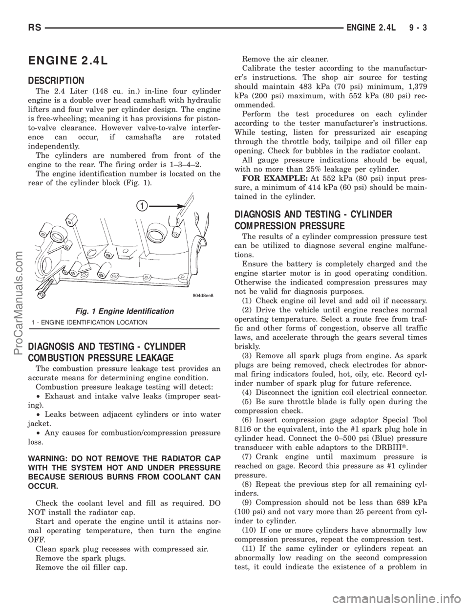
The engine identification number is located on the
rear of the cylinder block (Fig. 1).
DIAGNOSIS AND TESTING - CYLINDER
COMBUSTION PRESSURE LEAKAGE
The combustion pressure leakage test provides an
accurate means for determining engine condition.
Combustion pressure leakage testing will detect:
²Exhaust and intake valve leaks (improper seat-
ing).
²Leaks between adjacent cylinders or into water
jacket.
²Any causes for combustion/compression pressure
loss.
WARNING: DO NOT REMOVE THE RADIATOR CAP
WITH THE SYSTEM HOT AND UNDER PRESSURE
BECAUSE SERIOUS BURNS FROM COOLANT CAN
OCCUR.
Check the coolant level and fill as required. DO
NOT install the radiator cap.
Start and operate the engine until it attains nor-
mal operating temperature, then turn the engine
OFF.
Clean spark plug recesses with compressed air.
Remove the spark plugs.
Remove the oil filler cap.Remove the air cleaner.
Calibrate the tester according to the manufactur-
er's instructions. The shop air source for testing
should maintain 483 kPa (70 psi) minimum, 1,379
kPa (200 psi) maximum, with 552 kPa (80 psi) rec-
ommended.
Perform the test procedures on each cylinder
according to the tester manufacturer's instructions.
While testing, listen for pressurized air escaping
through the throttle body, tailpipe and oil filler cap
opening. Check for bubbles in the radiator coolant.
All gauge pressure indications should be equal,
with no more than 25% leakage per cylinder.
FOR EXAMPLE:At 552 kPa (80 psi) input pres-
sure, a minimum of 414 kPa (60 psi) should be main-
tained in the cylinder.
DIAGNOSIS AND TESTING - CYLINDER
COMPRESSION PRESSURE
The results of a cylinder compression pressure test
can be utilized to diagnose several engine malfunc-
tions.
Ensure the battery is completely charged and the
engine starter motor is in good operating condition.
Otherwise the indicated compression pressures may
not be valid for diagnosis purposes.
(1) Check engine oil level and add oil if necessary.
(2) Drive the vehicle until engine reaches normal
operating temperature. Select a route free from traf-
fic and other forms of congestion, observe all traffic
laws, and accelerate through the gears several times
briskly.
(3) Remove all spark plugs from engine. As spark
plugs are being removed, check electrodes for abnor-
mal firing indicators fouled, hot, oily, etc. Record cyl-
inder number of spark plug for future reference.
(4) Disconnect the ignition coil electrical connector.
(5) Be sure throttle blade is fully open during the
compression check.
(6) Insert compression gage adaptor Special Tool
8116 or the equivalent, into the #1 spark plug hole in
cylinder head. Connect the 0±500 psi (Blue) pressure
transducer with cable adaptors to the DRBIIIt.
(7) Crank engine until maximum pressure is
reached on gage. Record this pressure as #1 cylinder
pressure.
(8) Repeat the previous step for all remaining cyl-
inders.
(9) Compression should not be less than 689 kPa
(100 psi) and not vary more than 25 percent from cyl-
inder to cylinder.
(10) If one or more cylinders have abnormally low
compression pressures, repeat the compression test.
(11) If the same cylinder or cylinders repeat an
abnormally low reading on the second compression
test, it could indicate the existence of a problem in
Fig. 1 Engine Identification
1 - ENGINE IDENTIFICATION LOCATION
RSENGINE 2.4L9-3
ProCarManuals.com
Page 1161 of 2321
the cylinder in question.The recommended com-
pression pressures are to be used only as a
guide to diagnosing engine problems. An engine
should not be disassembled to determine the
cause of low compression unless some malfunc-
tion is present.
DIAGNOSIS AND TESTING - ENGINE OIL LEAK
Begin with a thorough visual inspection of the
engine, particularly at the area of the suspected leak.
If an oil leak source is not readily identifiable, the
following steps should be followed:
(1) Do not clean or degrease the engine at this
time because some solvents may cause rubber to
swell, temporarily stopping the leak.
(2) Add an oil soluble dye (use as recommended by
manufacturer). Start the engine and let idle for
approximately 15 minutes. Check the oil dipstick to
make sure the dye is thoroughly mixed as indicated
with a bright yellow color under a black light.
(3) Using a black light, inspect the entire engine
for fluorescent dye, particularly at the suspected area
of oil leak. If the oil leak is found and identified,
repair as necessary.
(4) If dye is not observed, drive the vehicle at var-
ious speeds for approximately 24 km (15 miles), and
repeat inspection.
(5)If the oil leak source is not positively
identified at this time, proceed with the air leak
detection test method as follows:
²Disconnect the fresh air hose (make-up air) at
the cylinder head cover and plug or cap the nipple on
the cover.
²Remove the PCV valve hose from the cylinder
head cover. Cap or plug the PCV valve nipple on the
cover.
²Attach an air hose with pressure gauge and reg-
ulator to the dipstick tube.
CAUTION: Do not subject the engine assembly to
more than 20.6 kpa (3 PSI) of test pressure.
²Gradually apply air pressure from 1 psi to 2.5
psi maximum while applying soapy water at the sus-
pected source. Adjust the regulator to the suitable
test pressure that provides the best bubbles which
will pinpoint the leak source. If the oil leak is
detected and identified, repair per service manual
procedures.
²If the leakage occurs at the crankshaft rear oil
seal area, refer to the section, Inspection for Rear
Seal Area Leak.
(6) If no leaks are detected, turn off the air supply.
Remove the air hose, all plugs, and caps. Install the
PCV valve and fresh air hose (make-up air). Proceed
to next step.(7) Clean the oil off the suspect oil leak area using
a suitable solvent. Drive the vehicle at various
speeds approximately 24 km (15 miles). Inspect the
engine for signs of an oil leak by using a black light.
NOTE: If oil leakage is observed at the dipstick tube
to block location; remove the tube, clean and reseal
using MoparTStud & Bearing Mount (press fit tube
applications only), and for O-ring style tubes,
remove tube and replace the O-ring seal.
INSPECTION FOR REAR SEAL AREA LEAKS
Since it is sometimes difficult to determine the
source of an oil leak in the rear seal area of the
engine, a more involved inspection is necessary. The
following steps should be followed to help pinpoint
the source of the leak.
If the leakage occurs at the crankshaft rear oil seal
area:
(1) Disconnect the battery.
(2) Raise the vehicle.
(3) Remove torque converter or clutch housing
cover and inspect rear of block for evidence of oil.
Use a black light to check for the oil leak. If a leak is
present in this area, remove transmission for further
inspection.
(a) Circular spray pattern generally indicates
seal leakage or crankshaft damage.
(b) Where leakage tends to run straight down,
possible causes are a porous block, oil gallery cup
plug, bedplate to cylinder block mating surfaces
and seal bore. See proper repair procedures for
these items.
(4) If no leaks are detected, pressurize the crank-
case as previously described.
CAUTION: Do not exceed 20.6 kPa (3 psi).
(5) If the leak is not detected, very slowly turn the
crankshaft and watch for leakage. If a leak is
detected between the crankshaft and seal while
slowly turning the crankshaft, it is possible the
crankshaft seal surface is damaged. The seal area on
the crankshaft could have minor nicks or scratches
that can be polished out with emery cloth.
CAUTION: Use extreme caution when crankshaft
polishing is necessary to remove minor nicks and
scratches. The crankshaft seal flange is especially
machined to complement the function of the rear oil
seal.
(6) For bubbles that remain steady with shaft
rotation, no further inspection can be done until dis-
assembled.
9 - 4 ENGINE 2.4LRS
ENGINE 2.4L (Continued)
ProCarManuals.com