2001 DODGE TOWN AND COUNTRY diagram
[x] Cancel search: diagramPage 563 of 2321

A eight-way power seat is standard on highline
models and optional on others. This option includes a
six-way adjustable seat cushion track and a two-way
power seat back.
The eight-way power seat is also available with the
heated seat and memory seat system that automati-
cally positions the power seat for two different driv-
ers. Refer toHeated Seat Systemfor more
information on the heated seat option. Refer toMem-
ory Systemin the Memory System section of this
group for more information on the memory system.
The power seat system includes the following com-
ponents:
²Power seat recliner
²Power seat switch
²Power seat track.
The power seat system with memory and heated
seat options includes the following components:
²Power seat recliner
²Power seat switch
²Power seat track.
²Memory Heated Seat Module (MHSM)
²Memory set switch
²Heated seat switch
²Electronic Vehicle Information Center (EVIC)
²Programmable Communications Interface (PCI)
data bus network
Refer to Wiring Diagrams for complete circuit dia-
grams. Following are general descriptions and opera-
tions for the major components in the power seat
system and memory seat system.
DESCRIPTION - MEMORY SEAT SYSTEM
An electronic memory and heated seat system is
available on some models. The memory system is
able to store and recall the driver side power seat
positions (including the power recliner position), and
both outside power mirror positions for two drivers.
For vehicles with a radio and heated / memory seat
system connected to the Programmable Communica-
tions Interface (PCI) data bus network, the memory
system is also able to store and recall radio station
presets for two drivers. The memory system also will
store and recall the last station listened to for each
driver, even if it is not one of the preset stations.
The memory system will automatically return to
all of these settings when the corresponding num-
bered and button of the memory switch on the driver
side seat side shield is depressed, or when the doors
are unlocked using the Remote Keyless Entry (RKE)
transmitter. A customer programmable feature of the
memory system allows the RKE recall of memory fea-
tures to be disabled in cases where there are more
than two drivers of the vehicle.
A Memory Heated Seat Module (MHSM) is used on
some models to control and integrate the many elec-tronic functions and features included in the memory
/ heated seat system.
The memory system includes the following compo-
nents:
²Heated seat switch
²Memory heated seat module (MHSM)
²Memory switch
²Position potentiometers on both outside power
mirrors
²Position potentiometers on the driver side power
seat track and power seat recliner motors.
²Radio receiver (if PCI data bus capable).
Certain functions and features of the memory system
rely upon resources shared with other electronic mod-
ules in the vehicle over the Programmable Communica-
tions Interface (PCI) J1850 data bus network. The PCI
data bus network allows the sharing of sensor informa-
tion. This helps to reduce wire harness complexity,
internal controller hardware, and component sensor cur-
rent loads. At the same time, this system provides
increased reliability, enhanced diagnostics, and allows
the addition of many new feature capabilities. For diag-
nosis of these electronic modules or of the PCI data bus
network, the use of a DRBtscan tool and the proper
Diagnostic Procedures manual are recommended.
The other electronic modules that may affect mem-
ory system operation are as follows:
²Body Control Module (BCM)- Refer toBody
Control Modulein Electronic Control Modules for
more information.
²
Electronic Vehicle Information Center (EVIC)
- Refer toElectronic Vehicle Information Center
in Overhead Console Systems for more information.
²Powertrain Control Module (PCM)- Refer to
Powertrain Control Modulein Electronic Control
Modules for more information.
²Radio Receiver- Refer toRadio Receiverin
Audio Systems for more information.
Refer toHeated Seat Systemfor more informa-
tion on the heated seat system. Refer toRemote
Keyless Entry Systemin Power Lock Systems for
more information on the RKE system. Refer to
Power Mirrorin Power Mirrors for more informa-
tion on the mirror position potentiometers. Refer to
Power Seat TrackandPower Seat Reclinerin
the Power Seat System section of this group for more
information on the driver side power seat position
potentiometers.
Refer toPower Seatin the Contents of Wiring
Diagrams for complete circuit diagrams. Following
are general descriptions of the remaining major com-
ponents in the factory-installed memory system.
OPERATION - POWER SEAT SYSTEM
The power seat system allows the driver and/or
front passenger seating positions to be adjusted elec-
8N - 50 POWER SEATSRS
POWER SEATS (Continued)
ProCarManuals.com
Page 564 of 2321
trically and independently using the separate power
seat switches found on the outboard seat cushion
side shield of each front seat. See the owner's manual
in the vehicle glove box for more information on the
features, use and operation of the power seat system.
OPERATION - MEMORY SYSTEM
The Memory Seat/Mirror Module (MSMM) will
drive a maximum of 2 motors at a time in a given
direction. If conflicting directions are requested, the
priority for response will be as follows:
²Seat Track Rearward
²Seat Front Down
²Seat Rear Down
²Recliner Rearward
²Seat Track Forward
²Seat Front Up
²Seat Rear Up
²Recliner Forward
The inputs from these switches to the MSMM is a
current limited battery source fed by the MSMM.
This protects the MSMM printed circuit board traces
from acting as fuses. All of these switch contact
inputs to the MSMM are normally closed to ground,
except when actuated.
Soft stops are incorporated to prevent the motor
from being driven into a stall. Should the seat have
restricted travel, refer to Resetting Soft Stops in this
section.
See the owner's manual in the vehicle glove box for
more information on the features, use and operation
of the memory system. For diagnosis of the MSM, the
PCI data bus, or the other electronic modules on the
PCI data bus that provide inputs and outputs for the
memory system, the use of a DRBtscan tool and the
proper Diagnostic Procedures manual are recom-
mended.
ELECTRONIC VEHICLE INFORMATION CENTER
The Electronic Vehicle Information Center (EVIC)
serves as the user interface for the memory system.
It displays memory system status messages and pro-
vides the user with the means for enabling and dis-
abling the many customer programmable features
available on the vehicle, including those for the mem-
ory system.
See the owner's manual in the vehicle glove box for
more information on the features, use and operation
of the EVIC. Refer toElectronic Vehicle Informa-
tion Centerin Overhead Console Systems for more
information on the EVIC.
DIAGNOSIS AND TESTING - POWER SEAT
SYSTEM
Following are tests that will help to diagnose the
hard wired components and circuits of the power seatsystem. However, if the vehicle is also equipped with
the optional memory system, these tests may not
prove conclusive in the diagnosis of the driver side
power seat. In order to obtain conclusive testing of
the driver side power seat with the memory system
option, the Programmable Communications Interface
(PCI) data bus network and all of the electronic mod-
ules that provide inputs to, or receive outputs from
the memory system components must be checked.
The most reliable, efficient, and accurate means to
diagnose the driver side power seat with the memory
system option requires the use of a DRBtscan tool
and the proper Diagnostic Procedures manual. The
DRBtscan tool can provide confirmation that the
PCI data bus is functional, that all of the electronic
modules are sending and receiving the proper mes-
sages on the PCI data bus, and that the memory sys-
tem is receiving the proper hard wired inputs and
relaying the proper hard wired outputs to perform its
driver side power seat functions.
WARNING: SOME VEHICLES ARE EQUIPPED WITH
SEATBACK MOUNTED AIRBAGS (Fig. 1). BEFORE
ATTEMPTING TO DIAGNOSE OR SERVICE ANY
SEAT OR POWER SEAT SYSTEM COMPONENT
YOU MUST FIRST DISCONNECT AND ISOLATE THE
BATTERY NEGATIVE CABLE. THEN WAIT TWO MIN-
UTES FOR THE SYSTEM CAPACITOR TO DIS-
CHARGE BEFORE FURTHER SYSTEM SERVICE.
THIS IS THE ONLY SURE WAY TO DISABLE THE
AIRBAG SYSTEM. FAILURE TO DO SO COULD
RESULT IN ACCIDENTAL AIRBAG DEPLOYMENT
AND POSSIBLE PERSONAL INJURY.
Before any testing of the power seat system is
attempted, the battery should be fully-charged and
all of the power seat system wire harness connections
and pins cleaned and tightened to ensure proper cir-
cuit continuity and ground paths. For complete cir-
cuit diagrams, refer toPower Seatin Wiring
Diagrams.
With the dome lamp on, apply the power seat
switch in the direction of the failure. If the dome
lamp dims, the seat may be jamming. Check under
and behind the seat for binding or obstructions. If
the dome lamp does not dim, proceed with testing of
the individual components and circuits.
DIAGNOSIS AND TESTING - MEMORY SYSTEM
CHECK AND RESET SOFT STOPS
To check and reset the power memory seat soft
stops, use the power seat control switches to move
the seat in one direction to the end of travel, allow a
couple of seconds before re-energizing the seat in the
same direction until it stops and for three additional
seconds after it stops. (The amount the seat moved
RSPOWER SEATS8N-51
POWER SEATS (Continued)
ProCarManuals.com
Page 567 of 2321
(7) Remove the power seat switch from the out-
board seat cushion side shield.
INSTALLATION
(1) Position the power seat switch onto the out-
board seat cushion side shield.
(2) Install and tighten the screws that secure the
power seat switch to the inside of the outboard seat
cushion side shield. Tighten the screws to 1.5 N´m
(14 in. lbs.).
(3) Reconnect the power seat wire harness connec-
tor to the power seat switch connector receptacle.
(4) Position the outboard seat cushion side shield
onto the seat cushion frame
(5) Install and tighten the screws that secure the
outboard seat cushion side shield to the seat cushion
frame. Tighten the screws to 1.5 N´m (14 in. lbs.).
(6) Reconnect the battery negative cable.
MEMORY SET SWITCH
DESCRIPTION
Vehicles equipped with the memory system have a
memory switch mounted to the driver side front door
trim panel. This switch is used to set and recall all of
the memory system settings for up to two drivers.
The memory switch is a resistor multiplexed unit
that is hard wired to the Body Control Module
(BCM). The BCM sends out the memory system set
and recall requests to the other electronic modules
over the Programmable Communications Interface
(PCI) data bus.
The memory switch cannot be adjusted or repaired
and, if faulty or damaged, it must be replaced. For
complete circuit diagrams, refer toWiring Dia-
grams.
OPERATION
The memory switch has three momentary switch
buttons labeled Set, 1 and 2. The Driver 1 and Driver
2 buttons are back-lit with Light-Emitting Diodes
(LED) for visibility, and are also color-coded to coin-
cide with the color-coded Driver 1 and Driver 2
Remote Keyless Entry (RKE) transmitters. The
Driver 1 memory switch button and RKE transmitter
are black, and the Driver 2 memory switch button
and RKE transmitter are gray. The memory switch
Set button also has an LED that will illuminate and
flash to indicate that the memory system is in the set
mode. This LED will automatically be extinguished
when a set request has been successfully completed.
See the owner's manual in the vehicle glove box for
more information on the features, use and operation
of the memory switch.
DIAGNOSIS AND TESTING - MEMORY SWITCH
For complete circuit diagrams, refer toWiring
Diagrams.
(1) Disconnect and isolate the battery negative
cable.
(2) Remove the driver side front door trim panel
switch bezel. Using a small thin bladed pry tool, gen-
tly pry the switch bezel away from the door trim
panel.
(3) Disconnect the memory switch wire harness
connector from the memory switch.
(4) Use an ohmmeter to test the resistances of the
memory switch in each switch position. See the Mem-
ory Switch Test chart. If OK, refer toMemory Sys-
temin the Diagnosis and Testing section of this
group. If not OK, replace the faulty memory switch.
MEMORY SWITCH TEST
MEMORY
SWITCH
POSITIONRESISTANCE
BETWEEN
PINSRESISTANCE
RANGE
(OHMS)
NEUTRAL 1&2 24560 1%
(24.56 k)
MEMORY 1 1&2 6830 1%
(6.83 k)
MEMORY 2 1&2 2090 1%
(2.09 k)
SET 1&2 4490 1%
(4.49 k)
REMOVAL
(1) Disconnect and isolate the battery negative
cable.
(2) Remove the front door trim panel switch bezel
from the driver side front door. Using a thin flat-
bladed pry tool, gently pry the switch bezel away
from the drivers door trim panel.
(3) Disconnect the memory switch wire harness
connector from the memory switch.
(4) Remove the two screws that secure the memory
switch to the back of the driver side front door trim
panel switch bezel.
(5) Remove the memory switch.
INSTALLATION
(1)Position the memory switch and install and
tighten the two screws that secure the memory switch
to the back of the driver side front door trim panel
switch bezel. Tighten the screws to 2.2 N´m (20 in. lbs.).
(2) Reconnect the memory switch wire harness
connector to the memory switch.
(3) Install the trim panel switch bezel onto the
driver side front door.
(4) Reconnect the battery negative cable.
8N - 54 POWER SEATSRS
DRIVER SEAT SWITCH (Continued)
ProCarManuals.com
Page 570 of 2321
DIAGNOSIS AND TESTING - POWER SEAT
RECLINER
Following are tests that will help to diagnose the
hard wired components and circuits of the power seat
system. However, if the vehicle is also equipped with
the optional memory system, these tests may not
prove conclusive in the diagnosis of the driver side
power seat. In order to obtain conclusive testing of
the driver side power seat with the memory system
option, the Programmable Communications Interface
(PCI) data bus network and all of the electronic mod-
ules that provide inputs to, or receive outputs from
the memory system components must be checked.The most reliable, efficient, and accurate means to
diagnose the driver side power seat with the memory
system option requires the use of a DRBtscan tool
and the proper Diagnostic Procedures manual. The
DRBtscan tool can provide confirmation that the
PCI data bus is functional, that all of the electronic
modules are sending and receiving the proper mes-
sages on the PCI data bus, and that the memory sys-
tem is receiving the proper hard wired inputs and
relaying the proper hard wired outputs to perform its
driver side power seat functions.
Actuate the power seat recliner switch to move the
power seat recliner adjuster in each direction. The
power seat recliner adjuster should move in both
directions. If the power seat recliner adjuster fails to
operate in only one direction, move the adjuster a
short distance in the opposite direction and test
again to be certain that the adjuster is not at its
travel limit. If the power seat recliner adjuster still
fails to operate in only one direction, refer toPower
Seat Switchin the Diagnosis and Testing section of
this group. If the power recliner adjuster fails to
operate in either direction, perform the following
tests. For complete circuit diagrams, refer toPower
Seatin Wiring Diagrams.
(1) Check the power seat circuit breaker under the
seat. If OK, go to Step 2. If not OK, replace the
faulty power seat circuit breaker.
(2) Check for battery voltage at the power seat cir-
cuit breaker under the seat. If OK, go to Step 3. If
not OK, repair the open fused B(+) circuit to the fuse
in the Intelligent Power Module as required.
(3) Remove the outboard seat cushion side shield
from the seat. Disconnect the seat wire harness con-
nector from the power seat switch connector recepta-
cle. Check for battery voltage at the fused B(+)
circuit cavity of the power seat wire harness connec-
tor for the power seat switch. If OK, go to Step 4. If
not OK, repair the open fused B(+) circuit to the
power seat circuit breaker under the seat as
required.
(4) Check for continuity between the ground cir-
cuit cavity of the power seat wire harness connector
for the power seat switch and a good ground. There
should be continuity. If OK, go to Step 5. If not OK,
repair the open ground circuit to ground as required.
(5) Test the power seat switch. Refer toPower
Seat Switchin the Diagnosis and Testing section of
this group. If the switch tests OK, test the circuits of
the power seat wire harness between the power seat
recliner adjuster motor and the power seat switch for
shorts or opens. If the circuits check OK, replace the
faulty power seat recliner unit. If the circuits are not
OK, repair the power seat wire harness as required.
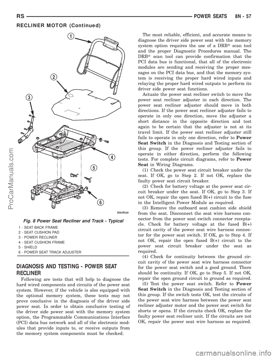
Fig. 8 Power Seat Recliner and Track - Typical
1 - SEAT BACK FRAME
2 - SEAT CUSHION PAD
3 - POWER RECLINER
4 - SEAT CUSHION FRAME
5 - SHIELD
6 - POWER SEAT TRACK ADJUSTER
RSPOWER SEATS8N-57
RECLINER MOTOR (Continued)
ProCarManuals.com
Page 572 of 2321
fails to operate in more than one direction, perform
the following tests. For complete circuit diagrams,
refer toPower Seatin Wiring Diagrams.
(1) Check the power seat circuit breaker under the
seat. If OK, go to Step 2. If not OK, replace the
faulty power seat circuit breaker.
(2) Check for battery voltage at the power seat cir-
cuit breaker under the seat. If OK, go to Step 3. If
not OK, repair the open fused B(+) circuit to the fuse
in the Intelligent Power Module as required.
(3) Remove the outboard seat cushion side shield
from the seat. Disconnect the seat wire harness con-
nector from the power seat switch connector recepta-
cle. Check for battery voltage at the fused B(+)
circuit cavity of the power seat wire harness connec-
tor for the power seat switch. If OK, go to Step 4. If
not OK, repair the open fused B(+) circuit to the
power seat circuit breaker under the seat as
required.
(4) Check for continuity between the ground cir-
cuit cavity of the power seat wire harness connector
for the power seat switch and a good ground. There
should be continuity. If OK, go to Step 5. If not OK,
repair the open ground circuit to ground as required.
(5) Test the power seat switch. Refer toPower
Seat Switchin the Diagnosis and Testing section of
this group. If the switch tests OK, test the circuits of
the power seat wire harness between the inoperative
power seat track adjuster motor and the power seat
switch for shorts or opens. If the circuits check OK,
replace the faulty power seat track unit. If the cir-
cuits are not OK, repair the power seat wire harness
as required.
REMOVAL
WARNING: SOME VEHICLES ARE EQUIPPED WITH
SEATBACK MOUNTED AIRBAGS. BEFORE
ATTEMPTING TO DIAGNOSE OR SERVICE ANY
SEAT OR POWER SEAT SYSTEM COMPONENT
YOU MUST FIRST DISCONNECT AND ISOLATE THE
BATTERY NEGATIVE CABLE. THEN WAIT TWO MIN-
UTES FOR THE SYSTEM CAPACITOR TO DIS-
CHARGE BEFORE FURTHER SYSTEM SERVICE.
THIS IS THE ONLY SURE WAY TO DISABLE THE
AIRBAG SYSTEM. FAILURE TO DO SO COULD
RESULT IN ACCIDENTAL AIRBAG DEPLOYMENT
AND POSSIBLE PERSONAL INJURY.(1) Remove the appropriate seat from the vehicle.
Refer to Body for the procedure.
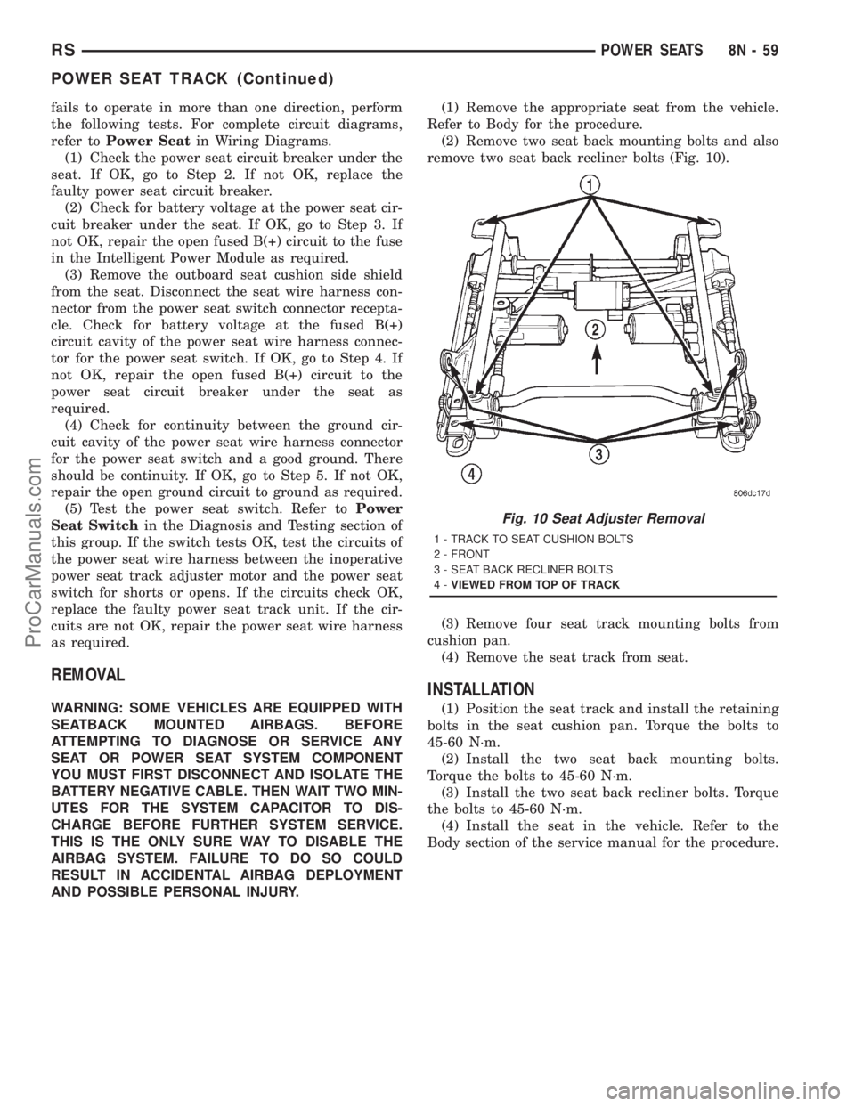
(2) Remove two seat back mounting bolts and also
remove two seat back recliner bolts (Fig. 10).
(3) Remove four seat track mounting bolts from
cushion pan.
(4) Remove the seat track from seat.
INSTALLATION
(1) Position the seat track and install the retaining
bolts in the seat cushion pan. Torque the bolts to
45-60 N´m.
(2) Install the two seat back mounting bolts.
Torque the bolts to 45-60 N´m.
(3) Install the two seat back recliner bolts. Torque
the bolts to 45-60 N´m.
(4) Install the seat in the vehicle. Refer to the
Body section of the service manual for the procedure.
Fig. 10 Seat Adjuster Removal
1 - TRACK TO SEAT CUSHION BOLTS
2 - FRONT
3 - SEAT BACK RECLINER BOLTS
4-VIEWED FROM TOP OF TRACK
RSPOWER SEATS8N-59
POWER SEAT TRACK (Continued)
ProCarManuals.com
Page 573 of 2321
POWER WINDOWS
TABLE OF CONTENTS
page page
POWER WINDOWS
DESCRIPTION...........................60
OPERATION.............................60
DIAGNOSIS AND TESTING.................60
POWER WINDOWS.....................60
VENT WINDOW MOTOR
DIAGNOSIS AND TESTING.................61
VENT WINDOW MOTOR.................61
REMOVAL..............................61INSTALLATION...........................62
WINDOW MOTOR
REMOVAL..............................62
WINDOW SWITCH
DIAGNOSIS AND TESTING.................62
WINDOW SWITCH......................62
REMOVAL..............................63
INSTALLATION...........................63
POWER WINDOWS
DESCRIPTION
The Power Window System is activated through
switches mounted on the driver and passenger door
panels.
OPERATION
Front door window lift motors use permanent type
magnets. The B+ and ground applied at the motor ter-
minal pins will cause the motor to rotate in one direc-
tion. Reversing current through the motor terminals
will cause the motor to rotate in the opposite direction.
The power window motors ground through the
master switch in the driver door by a black wire
attached to the left cowl panel. Refer to the appropri-
ate wiring information. The wiring information
includes wiring diagrams, proper wire and connector
repair procedures, details of wire harness routing
and retention, connector pin-out information and
location views for the various wire harness connec-
tors, splices and grounds.
The power rear vent windows, if equipped, are oper-
ated by switches mounted in the driver door switch
bezel. A separate switch is used for each window. Per-
manent magnet type motors connected to a crank sys-
tem are used to open and close the rear vent windows.
A battery positive and negative connection to either of
the two motor terminals will cause the motor to rotate
in one direction. Reversing current through these same
two connections will cause the motor to rotate in the
opposite direction. Refer to the appropriate wiring infor-
mation. The wiring information includes wiring dia-
grams, proper wire and connector repair procedures,
details of wire harness routing and retention, connector
pin-out information and location views for the various
wire harness connectors, splices and grounds.
DIAGNOSIS AND TESTING - POWER
WINDOWS
POWER WINDOW MOTOR TEST
If the power window motor is receiving proper cur-
rent and ground and does not operate, proceed with
motor test. Refer to the appropriate wiring informa-
tion. The wiring information includes wiring dia-
grams, proper wire and connector repair procedures,
details of wire harness routing and retention, connec-
tor pin-out information and location views for the
various wire harness connectors, splices and grounds.
(1) Remove front door trim panel and sound pad as
necessary to gain access to power window motor wire
connector, (Refer to 23 - BODY/DOOR - FRONT/
TRIM PANEL - REMOVAL).
(2) Disconnect power window motor wire connector
from door harness.
(3) Using two jumper wires, connect one to a bat-
tery (+) source and the other to a good ground (-).
(4) Connect the Negative (-) jumper probe to one of
the motor connector terminals.
(5) Momentarily touch the Positive (+) jumper
probe to the other motor connector terminal.
When positive probe is connected the motor should
rotate in one direction to either move window up or
down. If window is all the way up or down the motor
will grunt and the inner door panel will flex when
actuated in that one direction.
(6) Reverse jumper probes at the motor connector
terminals and window should now move in opposite
direction. If window does not move or grunt, replace
the motor.
If window moved completely up or down, reverse
the jumper probes and cycle window to the opposite
position to verify full operation.
If motor grunts and does not move, verify that reg-
ulator is not binding.
8N - 60 POWER WINDOWSRS
ProCarManuals.com
Page 574 of 2321
WIRING VOLTAGE TEST
The following wiring test determines whether or
not voltage is continuous through the body harness
to switch.
(1) Remove the power window switch and bezel
assembly from the driver door. (Refer to 8 - ELEC-
TRICAL/POWER WINDOWS/POWER WINDOW
SWITCH - REMOVAL).
(2) Disconnect wire connector from back of power
window switch.
(3) Switch ignition ON position.
(4) Connect the clip end of a 12 volt test light to
Pin 13 in door harness connector at the window
switch. Touch the test light probe to Pin 9 and then
to Pin 11.
²If the test light illuminates, the wiring circuit
between the battery and switch is OK.
²If the lamp does not illuminate, first check the
25 amp circuit breaker attached to the electrical dis-
tribution wiring bracket. If the circuit breaker is OK,
then check the 40 amp fuse (#28) in the Intelligent
Power Module. If both components are OK, then
check for a broken wire.
²Refer to the appropriate wiring information.
The wiring information includes wiring diagrams,
proper wire and connector repair procedures, details
of wire harness routing and retention, connector pin-
out information and location views for the various
wire harness connectors, splices and grounds.
VENT WINDOW MOTOR
DIAGNOSIS AND TESTING - VENT WINDOW
MOTOR
If the power vent window motor is receiving proper
current and ground and does not operate proceed
with motor test. Refer to the appropriate wiring
information. The wiring information includes wiring
diagrams, proper wire and connector repair proce-
dures, details of wire harness routing and retention,
connector pin-out information and location views for
the various wire harness connectors, splices and
grounds.
(1) Remove D-pillar trim panel necessary to gain
access to power vent window motor wire connector,
(Refer to 23 - BODY/INTERIOR/LEFT D-PILLAR
TRIM PANEL - REMOVAL) or (Refer to 23 - BODY/
INTERIOR/RIGHT D-PILLAR TRIM PANEL -
REMOVAL).
(2) Disconnect power vent window motor wire con-
nector from body harness.
(3) Using two jumper wires, connect one to a bat-
tery (+) source and the other to a good ground (-).
(4) Connect the Negative (-) jumper probe to one of
the motor connector terminals.(5) Momentarily touch the Positive (+) jumper
probe to the other motor connector terminal.
When positive probe is connected the motor should
rotate in one direction to either move window open or
closed. If window is all the way open or closed the
motor will grunt and the crank system will flex when
actuated in that one direction.
Reverse jumper probes at the motor connector ter-
minals and window should now move in opposite
direction. If window does not move or grunt, replace
the motor.
If window moved completely open or closed, reverse
the jumper probes and cycle window to the opposite
position to verify full operation.
If motor grunts and does not move, verify that
crank system is not binding.
REMOVAL
(1) Disconnect and isolate the battery negative
cable.
(2) Remove D-pillar trim panel. (Refer to 23 -
BODY/INTERIOR/LEFT D-PILLAR TRIM PANEL -
REMOVAL) or (Refer to 23 - BODY/INTERIOR/
RIGHT D-PILLAR TRIM PANEL - REMOVAL).
(3) Disconnect wire connector from power vent
motor.
(4) Using a flat bladed tool, carefully lift the circu-
lar actuator link tab. Remove link from window ball
socket.
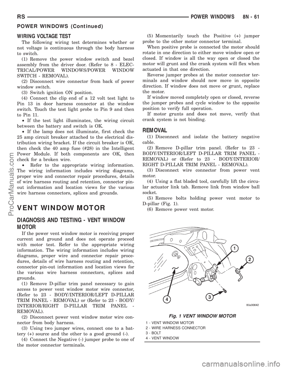
(5) Remove bolts holding power vent motor to
D-pillar (Fig. 1).
(6) Remove power vent motor.
Fig. 1 VENT WINDOW MOTOR
1 - VENT WINDOW MOTOR
2 - WIRE HARNESS CONNECTOR
3 - BOLT
4 - VENT WINDOW
RSPOWER WINDOWS8N-61
POWER WINDOWS (Continued)
ProCarManuals.com
Page 578 of 2321
POWER SYSTEMS
TABLE OF CONTENTS
page page
POWER FOLDAWAY MIRROR SWITCH
DESCRIPTION............................1
OPERATION.............................1REMOVAL...............................1
INSTALLATION............................2
POWER FOLDAWAY MIRROR
SWITCH
DESCRIPTION
These vehicles may be equipped with Power Fold-
away Mirrors. This feature allows both the driver
and passenger side view mirrors to fold inward
(retract) on demand. The vehicle has an additional
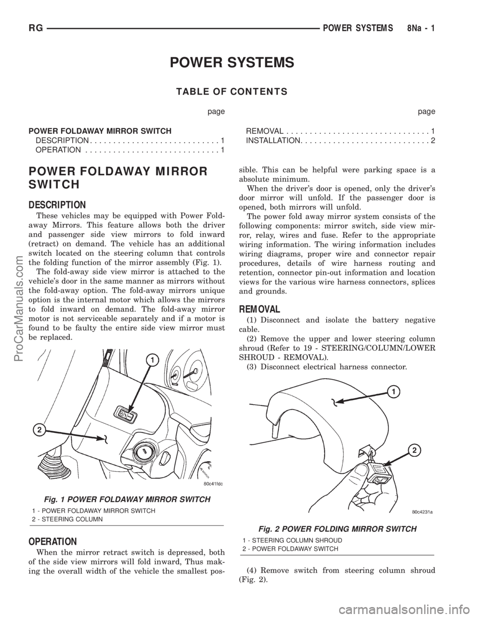
switch located on the steering column that controls
the folding function of the mirror assembly (Fig. 1).
The fold-away side view mirror is attached to the
vehicle's door in the same manner as mirrors without
the fold-away option. The fold-away mirrors unique
option is the internal motor which allows the mirrors
to fold inward on demand. The fold-away mirror
motor is not serviceable separately and if a motor is
found to be faulty the entire side view mirror must
be replaced.
OPERATION
When the mirror retract switch is depressed, both
of the side view mirrors will fold inward, Thus mak-
ing the overall width of the vehicle the smallest pos-sible. This can be helpful were parking space is a
absolute minimum.
When the driver's door is opened, only the driver's
door mirror will unfold. If the passenger door is
opened, both mirrors will unfold.
The power fold away mirror system consists of the
following components: mirror switch, side view mir-
ror, relay, wires and fuse. Refer to the appropriate
wiring information. The wiring information includes
wiring diagrams, proper wire and connector repair
procedures, details of wire harness routing and
retention, connector pin-out information and location
views for the various wire harness connectors, splices
and grounds.
REMOVAL
(1) Disconnect and isolate the battery negative
cable.
(2) Remove the upper and lower steering column
shroud (Refer to 19 - STEERING/COLUMN/LOWER
SHROUD - REMOVAL).
(3) Disconnect electrical harness connector.
(4) Remove switch from steering column shroud
(Fig. 2).
Fig. 1 POWER FOLDAWAY MIRROR SWITCH
1 - POWER FOLDAWAY MIRROR SWITCH
2 - STEERING COLUMN
Fig. 2 POWER FOLDING MIRROR SWITCH
1 - STEERING COLUMN SHROUD
2 - POWER FOLDAWAY SWITCH
RGPOWER SYSTEMS8Na-1
ProCarManuals.com