Page 1102 of 2321

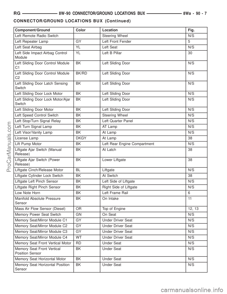
Component/Ground Color Location Fig.
Left Remote Radio Switch Steering Wheel N/S
Left Repeater Lamp GY Left Front Fender 5
Left Seat Airbag YL Left Seat N/S
Left Side Impact Airbag Control
ModuleYL Left B Pillar 30
Left Sliding Door Control Module
C1BK Left Sliding Door N/S
Left Sliding Door Control Module
C2BK/RD Left Sliding Door N/S
Left Sliding Door Latch Sensing
SwitchBK Left Sliding Door N/S
Left Sliding Door Lock Motor BK Left Sliding Door N/S
Left Sliding Door Lock Motor/Ajar
SwitchBK Left Sliding Door N/S
Left Sliding Door Motor BK Left Sliding Door N/S
Left Speed Control Switch BK Steering Wheel N/S
Left Stop/Turn Signal Relay BK Left Quarter Panel N/S
Left Turn Signal Lamp BK AT Lamp N/S
Left Visor/Vanity Lamp BK At Lamp N/S
License Lamp DKGY At Lamp 38
Lift Pump Motor BK Left Rear Engine Compartment N/S
Liftgate Ajar Switch (Manual
Release)BK At Latch 38
Liftgate Ajar Switch (Power
Release)BK Lower Liftgate 38
Liftgate Cinch/Release Motor BL Liftgate N/S
Liftgate Cylinder Lock Switch BK At Switch 38
Liftgate Left Pinch Sensor BK Left Side of Liftgate N/S
Liftgate Right Pinch Sensor BK Right Side of Liftgate N/S
Low Note Horn BK Left Frame Rail 6
Manifold Absolute Pressure
SensorBK On Intake 11
Mass Air Flow Sensor (Diesel) OR Top of Engine 12, 13
Memory Power Seat Switch GN On Seat N/S
Memory Seat/Mirror Module C1 GY Under Driver Seat N/S
Memory Seat/Mirror Module C2 GY Under Driver Seat N/S
Memory Seat/Mirror Module C3 GY Under Driver Seat N/S
Memory Seat/Mirror Module C4 WT Under Driver Seat N/S
Memory Seat Front Vertical Motor RD Under Seat N/S
Memory Seat Front Vertical
Position SensorBK Under Seat N/S
Memory Seat Horizontal Motor BK Under Seat N/S
Memory Seat Horizontal Position
SensorBK Under Seat N/S
RG8W-90 CONNECTOR/GROUND LOCATIONS BUX8Wa-90-7
CONNECTOR/GROUND LOCATIONS BUX (Continued)
ProCarManuals.com
Page 1103 of 2321

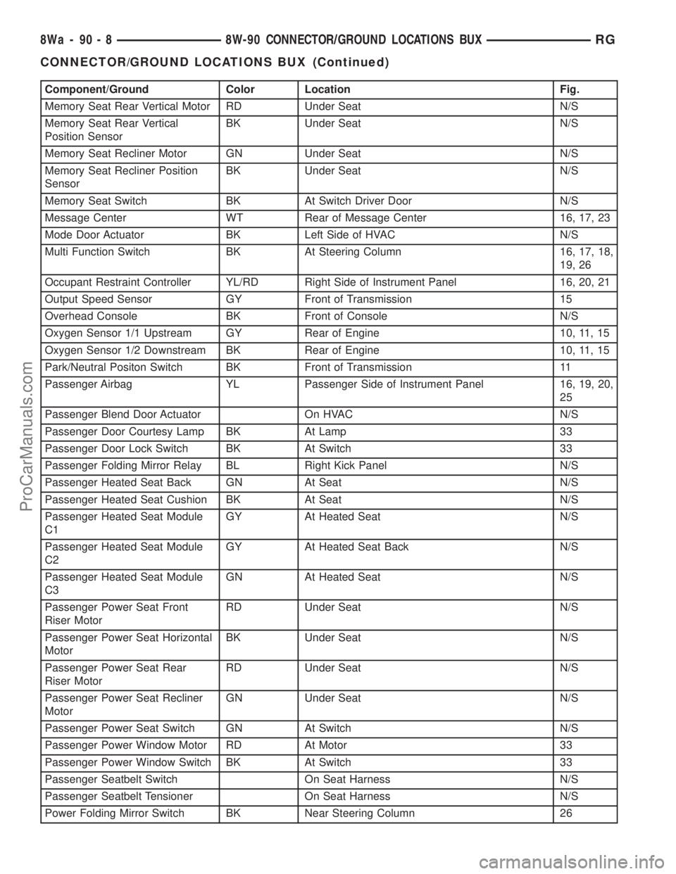
Component/Ground Color Location Fig.
Memory Seat Rear Vertical Motor RD Under Seat N/S
Memory Seat Rear Vertical
Position SensorBK Under Seat N/S
Memory Seat Recliner Motor GN Under Seat N/S
Memory Seat Recliner Position
SensorBK Under Seat N/S
Memory Seat Switch BK At Switch Driver Door N/S
Message Center WT Rear of Message Center 16, 17, 23
Mode Door Actuator BK Left Side of HVAC N/S
Multi Function Switch BK At Steering Column 16, 17, 18,
19, 26
Occupant Restraint Controller YL/RD Right Side of Instrument Panel 16, 20, 21
Output Speed Sensor GY Front of Transmission 15
Overhead Console BK Front of Console N/S
Oxygen Sensor 1/1 Upstream GY Rear of Engine 10, 11, 15
Oxygen Sensor 1/2 Downstream BK Rear of Engine 10, 11, 15
Park/Neutral Positon Switch BK Front of Transmission 11
Passenger Airbag YL Passenger Side of Instrument Panel 16, 19, 20,
25
Passenger Blend Door Actuator On HVAC N/S
Passenger Door Courtesy Lamp BK At Lamp 33
Passenger Door Lock Switch BK At Switch 33
Passenger Folding Mirror Relay BL Right Kick Panel N/S
Passenger Heated Seat Back GN At Seat N/S
Passenger Heated Seat Cushion BK At Seat N/S
Passenger Heated Seat Module
C1GY At Heated Seat N/S
Passenger Heated Seat Module
C2GY At Heated Seat Back N/S
Passenger Heated Seat Module
C3GN At Heated Seat N/S
Passenger Power Seat Front
Riser MotorRD Under Seat N/S
Passenger Power Seat Horizontal
MotorBK Under Seat N/S
Passenger Power Seat Rear
Riser MotorRD Under Seat N/S
Passenger Power Seat Recliner
MotorGN Under Seat N/S
Passenger Power Seat Switch GN At Switch N/S
Passenger Power Window Motor RD At Motor 33
Passenger Power Window Switch BK At Switch 33
Passenger Seatbelt Switch On Seat Harness N/S
Passenger Seatbelt Tensioner On Seat Harness N/S
Power Folding Mirror Switch BK Near Steering Column 26
8Wa - 90 - 8 8W-90 CONNECTOR/GROUND LOCATIONS BUXRG
CONNECTOR/GROUND LOCATIONS BUX (Continued)
ProCarManuals.com
Page 1140 of 2321

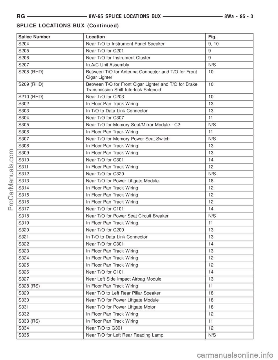
Splice Number Location Fig.
S204 Near T/O to Instrument Panel Speaker 9, 10
S205 Near T/O for C201 9
S206 Near T/O for Instrument Cluster 9
S207 In A/C Unit Assembly N/S
S208 (RHD) Between T/O for Antenna Connector and T/O for Front
Cigar Lighter10
S209 (RHD) Between T/O for Front Cigar Lighter and T/O for Brake
Transmission Shift Interlock Solenoid10
S210 (RHD) Near T/O for C203 10
S302 In Floor Pan Track Wiring 13
S303 In T/O to Data Link Connector 13
S304 Near T/O for C307 11
S305 Near T/O for Memory Seat/Mirror Module - C2 N/S
S306 In Floor Pan Track Wiring 11
S307 Near T/O for Memory Power Seat Switch N/S
S308 In Floor Pan Track Wiring 13
S309 In Floor Pan Track Wiring 13
S310 Near T/O for C301 14
S311 In Floor Pan Track Wiring 12
S312 Near T/O for C320 N/S
S313 Near T/O for Power Liftgate Module 18
S314 In Floor Pan Track Wiring 12
S315 In Floor Pan Track Wiring 12
S316 In Floor Pan Track Wiring 12
S317 Near T/O for C101 14
S318 Near T/O for Power Seat Circuit Breaker N/S
S319 In Floor Pan Track Wiring 11
S320 Near T/O for C200 13
S321 In T/O to Data Link Connector 13
S322 Near T/O for C301 14
S323 In Floor Pan Track Wiring 13
S324 In Floor Pan Track Wiring 12
S325 In Floor Pan Track Wiring 12
S326 Near T/O for C101 14
S327 Near Left Side Impact Airbag Module 13
S328 (RS) In Floor Pan Track Wiring 11
S329 Near T/O to Left Rear Pillar Speaker 18
S330 Near T/O for Power Liftgate Module 18
S331 Near T/O for Power Liftgate Motor 18
S332 In Floor Pan Track Wiring 12
S333 (RS) In Floor Pan Track Wiring 11
S334 Near T/O to G301 12
S335 Near T/O for Left Rear Reading Lamp N/S
RG8W-95 SPLICE LOCATIONS BUX8Wa-95-3
SPLICE LOCATIONS BUX (Continued)
ProCarManuals.com
Page 2071 of 2321

(9) Verify door latch operation.
(10) Install watershield and door trim panel.
TRIM PANEL
REMOVAL
(1) Remove the plug and remove screw attaching
door pull cup to inner door panel.
(2) Remove screws attaching trim panel to door
from below map pocket.
(3) If equipped, remove window crank. (Refer to 23
- BODY/DOOR - FRONT/WINDOW CRANK -
REMOVAL)(4) Remove screw holding door trim to door panel
from behind inside latch release handle .
(5) Disengage clips attaching door trim to door
frame around perimeter of panel.
(6) Lift trim panel upward to disengage flange
from inner belt molding at top of door.
(7) Tilt top of trim panel away from door to gain
access to latch linkage.
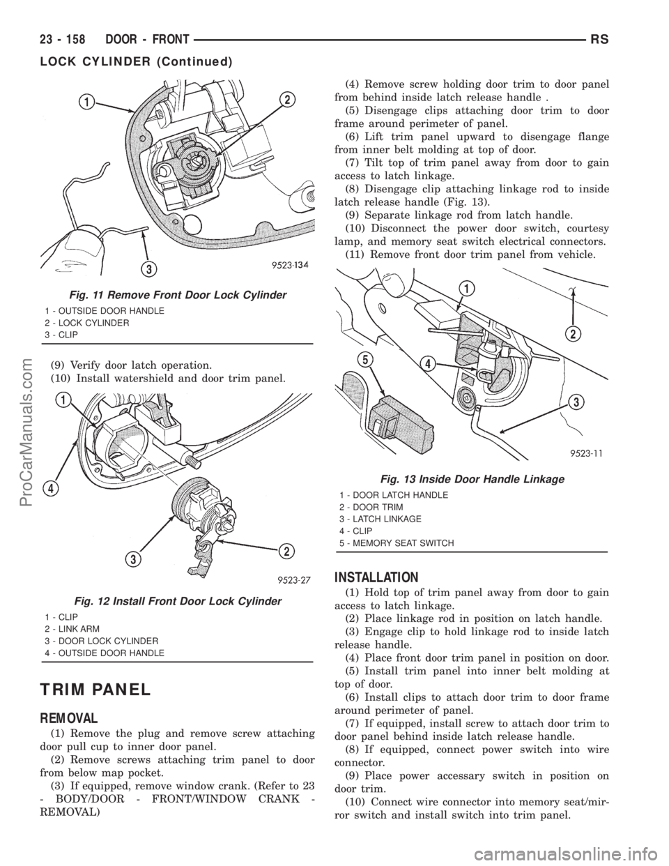
(8) Disengage clip attaching linkage rod to inside
latch release handle (Fig. 13).
(9) Separate linkage rod from latch handle.
(10) Disconnect the power door switch, courtesy
lamp, and memory seat switch electrical connectors.
(11) Remove front door trim panel from vehicle.
INSTALLATION
(1) Hold top of trim panel away from door to gain
access to latch linkage.
(2) Place linkage rod in position on latch handle.
(3) Engage clip to hold linkage rod to inside latch
release handle.
(4) Place front door trim panel in position on door.
(5) Install trim panel into inner belt molding at
top of door.
(6) Install clips to attach door trim to door frame
around perimeter of panel.
(7) If equipped, install screw to attach door trim to
door panel behind inside latch release handle.
(8) If equipped, connect power switch into wire
connector.
(9) Place power accessary switch in position on
door trim.
(10) Connect wire connector into memory seat/mir-
ror switch and install switch into trim panel.
Fig. 11 Remove Front Door Lock Cylinder
1 - OUTSIDE DOOR HANDLE
2 - LOCK CYLINDER
3 - CLIP
Fig. 12 Install Front Door Lock Cylinder
1 - CLIP
2 - LINK ARM
3 - DOOR LOCK CYLINDER
4 - OUTSIDE DOOR HANDLE
Fig. 13 Inside Door Handle Linkage
1 - DOOR LATCH HANDLE
2 - DOOR TRIM
3 - LATCH LINKAGE
4 - CLIP
5 - MEMORY SEAT SWITCH
23 - 158 DOOR - FRONTRS
LOCK CYLINDER (Continued)
ProCarManuals.com