2001 DODGE TOWN AND COUNTRY oil level
[x] Cancel search: oil levelPage 456 of 2321

INSTALLATION - 3.3/3.8L
(1) Install coil over studs on bracket.
(2) Install 2 bolts to ignition coil.
(3) Install 2 nuts to the ignition coil studs. Tighten
nuts and bolts.
(4) Connect the electrical connector to the ignition
coil.
(5) Install the ignition cables to the ignition coil.
(6) Reposition the Power steering reservoir. Slide
bracket over the mounting stud (Fig. 12).
(7) Install 2 bolts the Power steering reservoir to
intake manifold.
(8) Tighten the lower nut to stud on ignition coil
bracket.
(9) Install the throttle and speed control cables to
clip.
(10) Connect the negative battery cable.
KNOCK SENSOR
DESCRIPTION
The knock sensor threads into the cylinder block.
The knock sensor is designed to detect engine vibra-
tion that is caused by detonation.
OPERATION
When the knock sensor detects a knock in one of
the cylinders, it sends an input signal to the PCM. In
response, the PCM retards ignition timing for all cyl-
inders by a scheduled amount.Knock sensors contain a piezoelectric material
which constantly vibrates and sends an input voltage
(signal) to the PCM while the engine operates. As the
intensity of the crystal's vibration increases, the
knock sensor output voltage also increases.
The voltage signal produced by the knock sensor
increases with the amplitude of vibration. The PCM
receives as an input the knock sensor voltage signal.
If the signal rises above a predetermined level, the
PCM will store that value in memory and retard
ignition timing to reduce engine knock. If the knock
sensor voltage exceeds a preset value, the PCM
retards ignition timing for all cylinders. It is not a
selective cylinder retard.
The PCM ignores knock sensor input during engine
idle conditions. Once the engine speed exceeds a
specified value, knock retard is allowed.
Knock retard uses its own short term and long
term memory program.
Long term memory stores previous detonation
information in its battery-backed RAM. The maxi-
mum authority that long term memory has over tim-
ing retard can be calibrated.
Short term memory is allowed to retard timing up
to a preset amount under all operating conditions (as
long as rpm is above the minimum rpm) except WOT.
The PCM, using short term memory, can respond
quickly to retard timing when engine knock is
detected. Short term memory is lost any time the
ignition key is turned off.
NOTE: Over or under tightening affects knock sen-
sor performance, possibly causing improper spark
control.
REMOVAL - 2.4L
The knock sensor threads into the side of the cyl-
inder block in front of the starter (Fig. 13).
(1) Disconnect electrical connector from knock sen-
sor.
(2) Use a crow foot socket to remove the knock
sensors.
REMOVAL - 3.8L
The knock sensor threads into the side of the cyl-
inder block in the rear.
(1) Disconnect the negative battery cable.
(2) Raise vehicle and support.
(3) On All Wheel Drive vehicles remove the PTU
(Power Transfer Unit), refer to the Transmission sec-
tion for more information.
(4) Disconnect electrical connector from knock sen-
sor.
(5) Use a crow foot socket to remove the knock
sensor.
Fig. 12 IGNITION COIL BRACKET 3.3/3.8L
RSIGNITION CONTROL8I-7
IGNITION COIL (Continued)
ProCarManuals.com
Page 632 of 2321
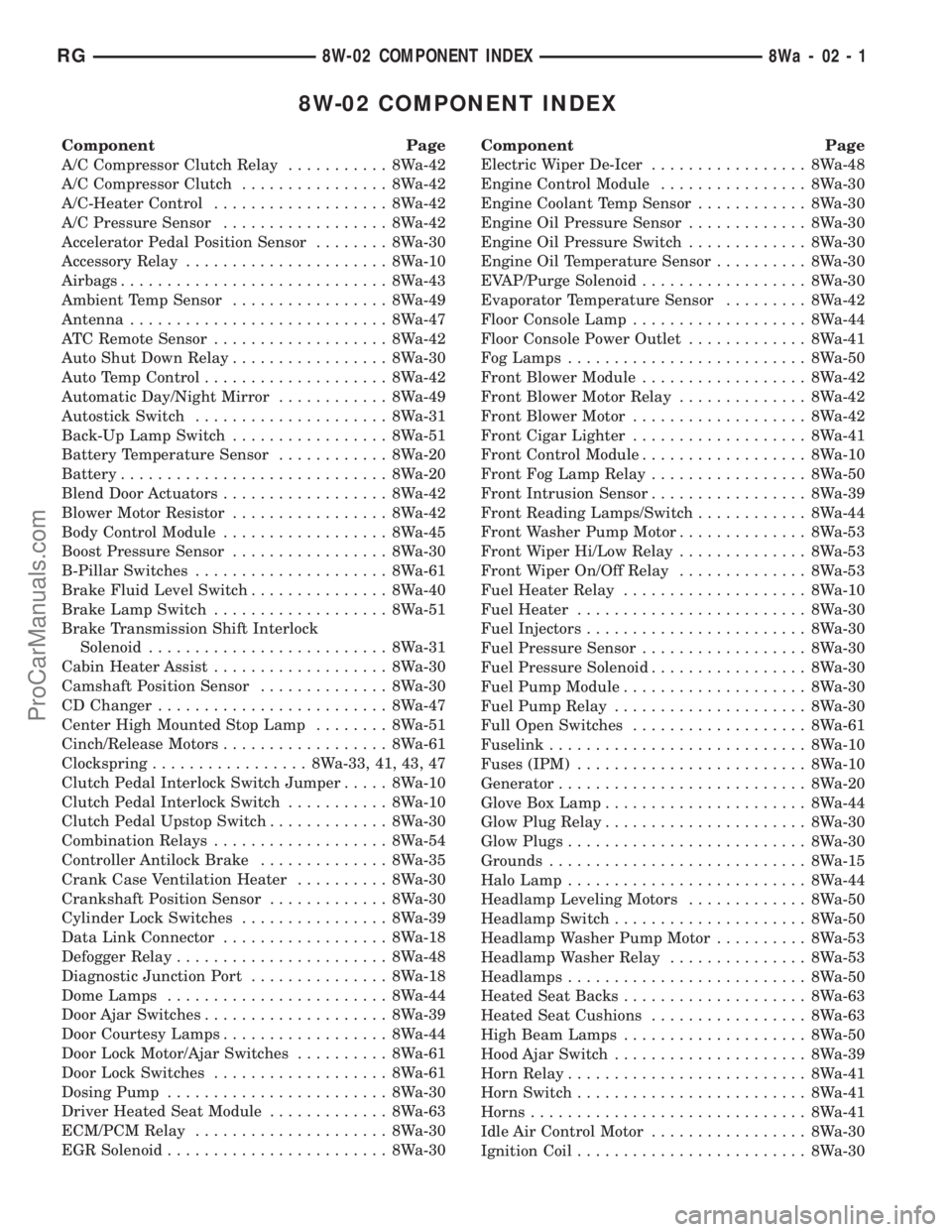
8W-02 COMPONENT INDEX
Component Page
A/C Compressor Clutch Relay........... 8Wa-42
A/C Compressor Clutch................ 8Wa-42
A/C-Heater Control................... 8Wa-42
A/C Pressure Sensor.................. 8Wa-42
Accelerator Pedal Position Sensor........ 8Wa-30
Accessory Relay...................... 8Wa-10
Airbags............................. 8Wa-43
Ambient Temp Sensor................. 8Wa-49
Antenna............................ 8Wa-47
ATC Remote Sensor................... 8Wa-42
Auto Shut Down Relay................. 8Wa-30
Auto Temp Control.................... 8Wa-42
Automatic Day/Night Mirror............ 8Wa-49
Autostick Switch..................... 8Wa-31
Back-Up Lamp Switch................. 8Wa-51
Battery Temperature Sensor............ 8Wa-20
Battery............................. 8Wa-20
Blend Door Actuators.................. 8Wa-42
Blower Motor Resistor................. 8Wa-42
Body Control Module.................. 8Wa-45
Boost Pressure Sensor................. 8Wa-30
B-Pillar Switches..................... 8Wa-61
Brake Fluid Level Switch............... 8Wa-40
Brake Lamp Switch................... 8Wa-51
Brake Transmission Shift Interlock
Solenoid.......................... 8Wa-31
Cabin Heater Assist................... 8Wa-30
Camshaft Position Sensor.............. 8Wa-30
CD Changer......................... 8Wa-47
Center High Mounted Stop Lamp........ 8Wa-51
Cinch/Release Motors.................. 8Wa-61
Clockspring................. 8Wa-33, 41, 43, 47
Clutch Pedal Interlock Switch Jumper..... 8Wa-10
Clutch Pedal Interlock Switch........... 8Wa-10
Clutch Pedal Upstop Switch............. 8Wa-30
Combination Relays................... 8Wa-54
Controller Antilock Brake.............. 8Wa-35
Crank Case Ventilation Heater.......... 8Wa-30
Crankshaft Position Sensor............. 8Wa-30
Cylinder Lock Switches................ 8Wa-39
Data Link Connector.................. 8Wa-18
Defogger Relay....................... 8Wa-48
Diagnostic Junction Port............... 8Wa-18
Dome Lamps........................ 8Wa-44
Door Ajar Switches.................... 8Wa-39
Door Courtesy Lamps.................. 8Wa-44
Door Lock Motor/Ajar Switches.......... 8Wa-61
Door Lock Switches................... 8Wa-61
Dosing Pump........................ 8Wa-30
Driver Heated Seat Module............. 8Wa-63
ECM/PCM Relay..................... 8Wa-30
EGR Solenoid........................ 8Wa-30Component Page
Electric Wiper De-Icer................. 8Wa-48
Engine Control Module................ 8Wa-30
Engine Coolant Temp Sensor............ 8Wa-30
Engine Oil Pressure Sensor............. 8Wa-30
Engine Oil Pressure Switch............. 8Wa-30
Engine Oil Temperature Sensor.......... 8Wa-30
EVAP/Purge Solenoid.................. 8Wa-30
Evaporator Temperature Sensor......... 8Wa-42
Floor Console Lamp................... 8Wa-44
Floor Console Power Outlet............. 8Wa-41
Fog Lamps.......................... 8Wa-50
Front Blower Module.................. 8Wa-42
Front Blower Motor Relay.............. 8Wa-42
Front Blower Motor................... 8Wa-42
Front Cigar Lighter................... 8Wa-41
Front Control Module.................. 8Wa-10
Front Fog Lamp Relay................. 8Wa-50
Front Intrusion Sensor................. 8Wa-39
Front Reading Lamps/Switch............ 8Wa-44
Front Washer Pump Motor.............. 8Wa-53
Front Wiper Hi/Low Relay.............. 8Wa-53
Front Wiper On/Off Relay.............. 8Wa-53
Fuel Heater Relay.................... 8Wa-10
Fuel Heater......................... 8Wa-30
Fuel Injectors........................ 8Wa-30
Fuel Pressure Sensor.................. 8Wa-30
Fuel Pressure Solenoid................. 8Wa-30
Fuel Pump Module.................... 8Wa-30
Fuel Pump Relay..................... 8Wa-30
Full Open Switches................... 8Wa-61
Fuselink............................ 8Wa-10
Fuses (IPM)......................... 8Wa-10
Generator........................... 8Wa-20
Glove Box Lamp...................... 8Wa-44
Glow Plug Relay...................... 8Wa-30
Glow Plugs.......................... 8Wa-30
Grounds............................ 8Wa-15
Halo Lamp.......................... 8Wa-44
Headlamp Leveling Motors............. 8Wa-50
Headlamp Switch..................... 8Wa-50
Headlamp Washer Pump Motor.......... 8Wa-53
Headlamp Washer Relay............... 8Wa-53
Headlamps.......................... 8Wa-50
Heated Seat Backs.................... 8Wa-63
Heated Seat Cushions................. 8Wa-63
High Beam Lamps.................... 8Wa-50
Hood Ajar Switch..................... 8Wa-39
Horn Relay.......................... 8Wa-41
Horn Switch......................... 8Wa-41
Horns.............................. 8Wa-41
Idle Air Control Motor................. 8Wa-30
Ignition Coil......................... 8Wa-30
RG8W-02 COMPONENT INDEX8Wa-02-1
ProCarManuals.com
Page 636 of 2321
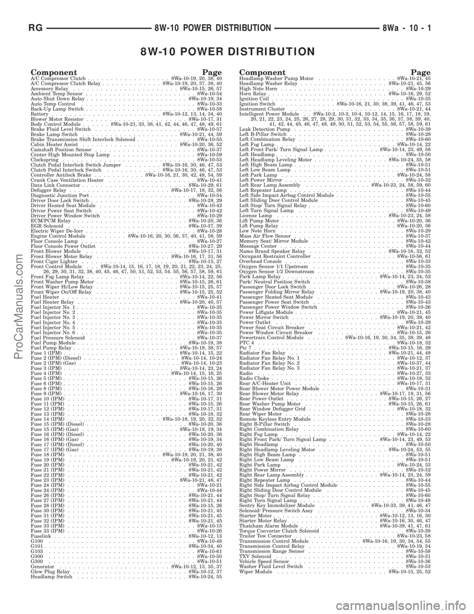
8W-10 POWER DISTRIBUTION
Component PageA/C Compressor Clutch..................8Wa-10-19, 20, 38, 40
A/C Compressor Clutch Relay.............8Wa-10-19, 20, 37, 38, 40
Accessory Relay.......................8Wa-10-15, 26, 57
Ambient Temp Sensor........................8Wa-10-54
Auto Shut Down Relay......................8Wa-10-19, 34
Auto Temp Control.........................8Wa-10-33
Back-Up Lamp Switch........................8Wa-10-58
Battery........................8Wa-10-12, 13, 14, 34, 40
Blower Motor Resistor......................8Wa-10-17, 31
Body Control Module......8Wa-10-21, 33, 38, 41, 42, 44, 46, 47, 48, 49, 61
Brake Fluid Level Switch......................8Wa-10-57
Brake Lamp Switch.....................8Wa-10-21, 44, 59
Brake Transmission Shift Interlock Solenoid.............8Wa-10-55
Cabin Heater Assist.....................8Wa-10-20, 36, 52
Camshaft Position Sensor......................8Wa-10-37
Center High Mounted Stop Lamp..................8Wa-10-59
Clockspring.............................8Wa-10-53
Clutch Pedal Interlock Switch Jumper........8Wa-10-16, 30, 46, 47, 53
Clutch Pedal Interlock Switch............8Wa-10-16, 30, 46, 47, 53
Controller Antilock Brake...........8Wa-10-16, 21, 30, 42, 48, 54, 59
Crank Case Ventilation Heater...................8Wa-10-41
Data Link Connector.......................8Wa-10-29, 61
Defogger Relay......................8Wa-10-17, 18, 32, 56
Diagnostic Junction Port.......................8Wa-10-54
Driver Door Lock Switch.....................8Wa-10-28, 29
Driver Heated Seat Module.....................8Wa-10-42
Driver Power Seat Switch......................8Wa-10-42
Driver Power Window Switch....................8Wa-10-29
ECM/PCM Relay.........................8Wa-10-20, 36
EGR Solenoid..........................8Wa-10-37, 39
Electric Wiper De-Icer........................8Wa-10-28
Engine Control Module........8Wa-10-16, 20, 30, 36, 37, 40, 41, 58, 59
Floor Console Lamp.........................8Wa-10-27
Floor Console Power Outlet...................8Wa-10-27, 29
Front Blower Module......................8Wa-10-17, 31
Front Blower Motor Relay................8Wa-10-16, 17, 31, 56
Front Cigar Lighter.......................8Wa-10-15, 27
Front Control Module . . . 8Wa-10-14, 15, 16, 17, 18, 19, 20, 21, 22, 23, 24, 25,
26, 29, 30, 31, 32, 38, 40, 45, 46, 47, 50, 51, 52, 53, 54. 55, 56, 57, 58, 59, 61
Front Fog Lamp Relay....................8Wa-10-14, 22, 56
Front Washer Pump Motor..................8Wa-10-15, 26, 61
Front Wiper Hi/Low Relay..................8Wa-10-15, 25, 57
Front Wiper On/Off Relay..................8Wa-10-15, 25, 52
Fuel Heater.............................8Wa-10-41
Fuel Heater Relay......................8Wa-10-20, 40, 57
Fuel Injector No. 1..........................8Wa-10-35
Fuel Injector No. 2..........................8Wa-10-35
Fuel Injector No. 3..........................8Wa-10-35
Fuel Injector No. 4..........................8Wa-10-35
Fuel Injector No. 5..........................8Wa-10-35
Fuel Injector No. 6..........................8Wa-10-35
Fuel Pressure Solenoid.......................8Wa-10-37
Fuel Pump Module........................8Wa-10-19, 38
Fuel Pump Relay.......................8Wa-10-19, 38, 57
Fuse 1 (IPM).........................8Wa-10-14, 15, 22
Fuse 2 (IPM) (Diesel).....................8Wa-10-14, 10-24
Fuse 2 (IPM) (Gas)......................8Wa-10-14, 10-23
Fuse 3 (IPM).........................8Wa-10-14, 23, 24
Fuse 4 (IPM).......................8Wa-10-14, 15, 16, 25
Fuse 5 (IPM)...........................8Wa-10-15, 26
Fuse 6 (IPM)...........................8Wa-10-15, 26
Fuse 8 (IPM)...........................8Wa-10-16, 29
Fuse 9 (IPM).........................8Wa-10-16, 17, 30
Fuse 10 (IPM)..........................8Wa-10-17, 31
Fuse 11 (IPM)..........................8Wa-10-15, 26
Fuse 12 (IPM)..........................8Wa-10-17, 31
Fuse 13 (IPM)..........................8Wa-10-18, 32
Fuse 14 (IPM)....................8Wa-10-18, 19, 20, 32, 52
Fuse 15 (IPM) (Diesel)......................8Wa-10-20, 36
Fuse 15 (IPM) (Gas).....................8Wa-10-18, 19, 34
Fuse 16 (IPM) (Diesel)......................8Wa-10-20, 36
Fuse 16 (IPM) (Gas).......................8Wa-10-19, 34
Fuse 17 (IPM) (Diesel)......................8Wa-10-20, 40
Fuse 17 (IPM) (Gas).......................8Wa-10-19, 38
Fuse 18 (IPM)....................8Wa-10-19, 20, 21, 38, 40
Fuse 19 (IPM)......................8Wa-10-19, 20, 21, 42
Fuse 20 (IPM)..........................8Wa-10-21, 42
Fuse 21 (IPM)..........................8Wa-10-21, 42
Fuse 22 (IPM)..........................8Wa-10-21, 42
Fuse 23 (IPM)........................8Wa-10-21, 46, 47
Fuse 24 (IPM)............................8Wa-10-21
Fuse 24 (IPM)............................8Wa-10-44
Fuse 26 (IPM)..........................8Wa-10-21, 44
Fuse 27 (IPM)..........................8Wa-10-21, 44
Fuse 28 (IPM)..........................8Wa-10-15, 26
Fuse 30 (IPM)..........................8Wa-10-21, 45
Fuse 31 (IPM)..........................8Wa-10-21, 45
Fuse 32 (IPM)..........................8Wa-10-21, 45
Fuse 33 (IPM)............................8Wa-10-15
Fuse 33 (IPM)............................8Wa-10-26
Fuselink.............................8Wa-10-12, 13
G100................................8Wa-10-48
G101...............................8Wa-10-34, 40
G103................................8Wa-10-61
G300................................8Wa-10-50
G300................................8Wa-10-51
Generator........................8Wa-10-12, 13, 35, 37
Glow Plug Relay.........................8Wa-10-12, 37
Headlamp Switch........................8Wa-10-24, 55Component PageHeadlamp Washer Pump Motor.................8Wa-10-21, 45
Headlamp Washer Relay...................8Wa-10-21, 45, 56
High Note Horn...........................8Wa-10-29
Horn Relay..........................8Wa-10-16, 29, 52
Ignition Coil.............................8Wa-10-35
Ignition Switch............8Wa-10-16, 21, 30, 38, 39, 41, 46, 47, 53
Instrument Cluster.......................8Wa-10-21, 44
Intelligent Power Module . . 8Wa-10-2, 10-3, 10-4, 10-12, 14, 15, 16, 17, 18, 19,
20, 21, 22, 23, 24, 25, 26, 27, 28, 29, 30, 31, 32, 33, 34, 35, 36, 37, 38, 39, 40,
41, 42, 44, 45, 46, 47, 48, 49, 50, 51, 52, 53, 54, 55, 56, 57, 58, 59, 61
Leak Detection Pump........................8Wa-10-39
Left B-Pillar Switch.........................8Wa-10-28
Left Combination Relay.......................8Wa-10-60
Left Fog Lamp..........................8Wa-10-14, 22
Left Front Park/ Turn Signal Lamp............8Wa-10-14, 23, 49, 58
Left Headlamp............................8Wa-10-50
Left Headlamp Leveling Motor................8Wa-10-24, 55, 58
Left High Beam Lamp........................8Wa-10-51
Left Low Beam Lamp........................8Wa-10-51
Left Park Lamp.........................8Wa-10-24, 58
Left Power Mirror..........................8Wa-10-32
Left Rear Lamp Assembly..............8Wa-10-23, 24, 58, 59, 60
Left Repeater Lamp.........................8Wa-10-44
Left Side Impact Airbag Control Module...............8Wa-10-55
Left Sliding Door Control Module..................8Wa-10-45
Left Stop/ Turn Signal Relay.....................8Wa-10-60
Left Turn Signal Lamp.......................8Wa-10-49
License Lamp........................8Wa-10-23, 24, 58
Lift Pump Motor.........................8Wa-10-20, 36
Lift Pump Relay.........................8Wa-10-20, 36
Low Note Horn...........................8Wa-10-29
Mass Air Flow Sensor........................8Wa-10-37
Memory Seat/ Mirror Module....................8Wa-10-42
Message Center...........................8Wa-10-44
Name Brand Speaker Relay.................8Wa-10-18, 32, 52
Occupant Restraint Controller..................8Wa-10-56, 61
Overhead Console..........................8Wa-10-33
Oxygen Sensor 1/1 Upstream....................8Wa-10-35
Oxygen Sensor 1/2 Downstream...................8Wa-10-35
Park Lamp Relay.....................8Wa-10-14, 23, 24, 52
Park/ Neutral Position Switch....................8Wa-10-58
Passenger Door Lock Switch...................8Wa-10-26, 28
Passenger Folding Mirror Relay.............8Wa-10-19, 20, 38, 40
Passenger Heated Seat Module...................8Wa-10-43
Passenger Power Seat Switch....................8Wa-10-43
Passenger Power Window Switch..................8Wa-10-26
Power Liftgate Module......................8Wa-10-21, 45
Power Mirror Switch...................8Wa-10-19, 20, 39, 40
Power Outlet............................8Wa-10-29
Power Seat Circuit Breaker...................8Wa-10-21, 42
Power Window Circuit Breaker.................8Wa-10-15, 26
Powertrain Control Module........8Wa-10-16, 19, 30, 34, 35, 38, 39, 48
PTC4 ..............................8Wa-10-18, 32
Ptc7.............................8Wa-10-15, 16, 29
Radiator Fan Relay.....................8Wa-10-21, 44, 48
Radiator Fan Relay No. 1....................8Wa-10-12, 37
Radiator Fan Relay No. 2....................8Wa-10-37, 44
Radiator Fan Relay No. 3....................8Wa-10-21, 37
Radio..............................8Wa-10-27, 33
Radio Choke...........................8Wa-10-18, 32
Rear A/C-Heater Unit......................8Wa-10-17, 31
Rear Blower Motor Power Module..................8Wa-10-31
Rear Blower Motor Relay.................8Wa-10-17, 18, 31, 56
Rear Power Outlet......................8Wa-10-15, 26, 27
Rear Washer Pump Motor..................8Wa-10-15, 26, 61
Rear Window Defogger Grid...................8Wa-10-18, 32
Rear Wiper Motor..........................8Wa-10-28
Remote Keyless Entry Module....................8Wa-10-33
Right B-Pillar Switch........................8Wa-10-28
Right Combination Relay......................8Wa-10-60
Right Fog Lamp.........................8Wa-10-14, 22
Right Front Park/ Turn Signal Lamp...........8Wa-10-14, 23, 49, 53
Right Headlamp...........................8Wa-10-50
Right Headlamp Leveling Motor...............8Wa-10-24, 53, 55
Right High Beam Lamp.......................8Wa-10-51
Right Low Beam Lamp.......................8Wa-10-51
Right Park Lamp........................8Wa-10-24, 53
Right Power Mirror.........................8Wa-10-32
Right Rear Lamp Assembly................8Wa-10-14, 23, 24, 59
Right Repeater Lamp........................8Wa-10-44
Right Side Impact Airbag Control Module..............8Wa-10-55
Right Sliding Door Control Module.................8Wa-10-45
Right Stop/ Turn Signal Relay....................8Wa-10-60
Right Turn Signal Lamp.......................8Wa-10-49
Sentry Key Immobilizer Module...........8Wa-10-33, 39, 41, 46, 47
Solenoid/ Pressure Switch Assy...................8Wa-10-34
Starter Motor.......................8Wa-10-12, 13, 16, 30
Starter Motor Relay...................8Wa-10-16, 30, 46, 47
Thatcham Alarm Module.................8Wa-10-39, 41, 47, 61
Torque Converter Clutch Solenoid..................8Wa-10-39
Trailer Tow Connector......................8Wa-10-23, 58
Transmission Control Module...........8Wa-10-16, 19, 30, 34, 54, 55
Transmission Control Relay...................8Wa-10-19, 34
Transmission Range Sensor.....................8Wa-10-58
TXV Solenoid............................8Wa-10-31
Vehicle Speed Sensor........................8Wa-10-36
Washer Fluid Level Switch.....................8Wa-10-53
Wiper Module........................8Wa-10-15, 25, 52
RG8W-10 POWER DISTRIBUTION8Wa-10-1
ProCarManuals.com
Page 802 of 2321

8W-40 INSTRUMENT CLUSTER
Component Page
Body Control Module . . 8Wa-40-2, 3, 4, 5, 6, 7, 8, 9,
10, 11
Brake Fluid Level Switch............. 8Wa-40-9
Clockspring........................ 8Wa-40-9
Diagnostic Junction Port . . 8Wa-40-2, 3, 4, 5, 6, 7, 8,
9, 12
Engine Control Module.......... 8Wa-40-8, 9, 12
Engine Coolant Temp Sensor........ 8Wa-40-7, 8
Engine Oil Pressure Sensor........... 8Wa-40-12
Engine Oil Pressure Switch........... 8Wa-40-12
Front Control Module................ 8Wa-40-9
Fuel Pump Module.................. 8Wa-40-2
Fuse 24 (IPM)...................... 8Wa-40-2
G200.................... 8Wa-40-2, 10, 11, 12
G300............................. 8Wa-40-9
Instrument Cluster . 8Wa-40-2, 3, 4, 5, 6, 7, 8, 9, 10,
11 , 1 2
Intelligent Power Module........... 8Wa-40-2, 9
Left Front Door Ajar Switch........... 8Wa-40-3
Left Front Door Lock Motor/Ajar Switch . . 8Wa-40-3
Left Sliding Door Control Module....... 8Wa-40-4
Left Sliding Door Latch Sensing Switch . . 8Wa-40-4
Left Sliding Door Lock Motor/Ajar Switch . 8Wa-40-4
Left Speed Control Switch............. 8Wa-40-9
Liftgate Ajar Switch................. 8Wa-40-3
Liftgate Cinch/Release Motor.......... 8Wa-40-3
Message Center.................. 8Wa-40-6, 12
Multi- Function Switch............... 8Wa-40-6
Occupant Restraint Controller......... 8Wa-40-2
Parking Brake Switch............ 8Wa-40-10, 11
Powertrain Control Module....... 8Wa-40-7, 9, 12
Right Front Door Ajar Switch.......... 8Wa-40-3
Right Front Door Lock Motor/Ajar Switch . 8Wa-40-3
Right Sliding Door Control Module...... 8Wa-40-5
Right Sliding Door Latch Sensing Switch . 8Wa-40-5
Right Sliding Door Lock Motor/Ajar Switch. 8Wa-40-5
Right Speed Control Switch........... 8Wa-40-9
Traction Control Switch............ 8Wa-40-7, 8
Transmission Control Module.......... 8Wa-40-7
Vehicle Speed Sensor............... 8Wa-40-7, 8
Washer Fluid Level Switch............ 8Wa-40-9
RG8W-40 INSTRUMENT CLUSTER8Wa-40-1
ProCarManuals.com
Page 1159 of 2321
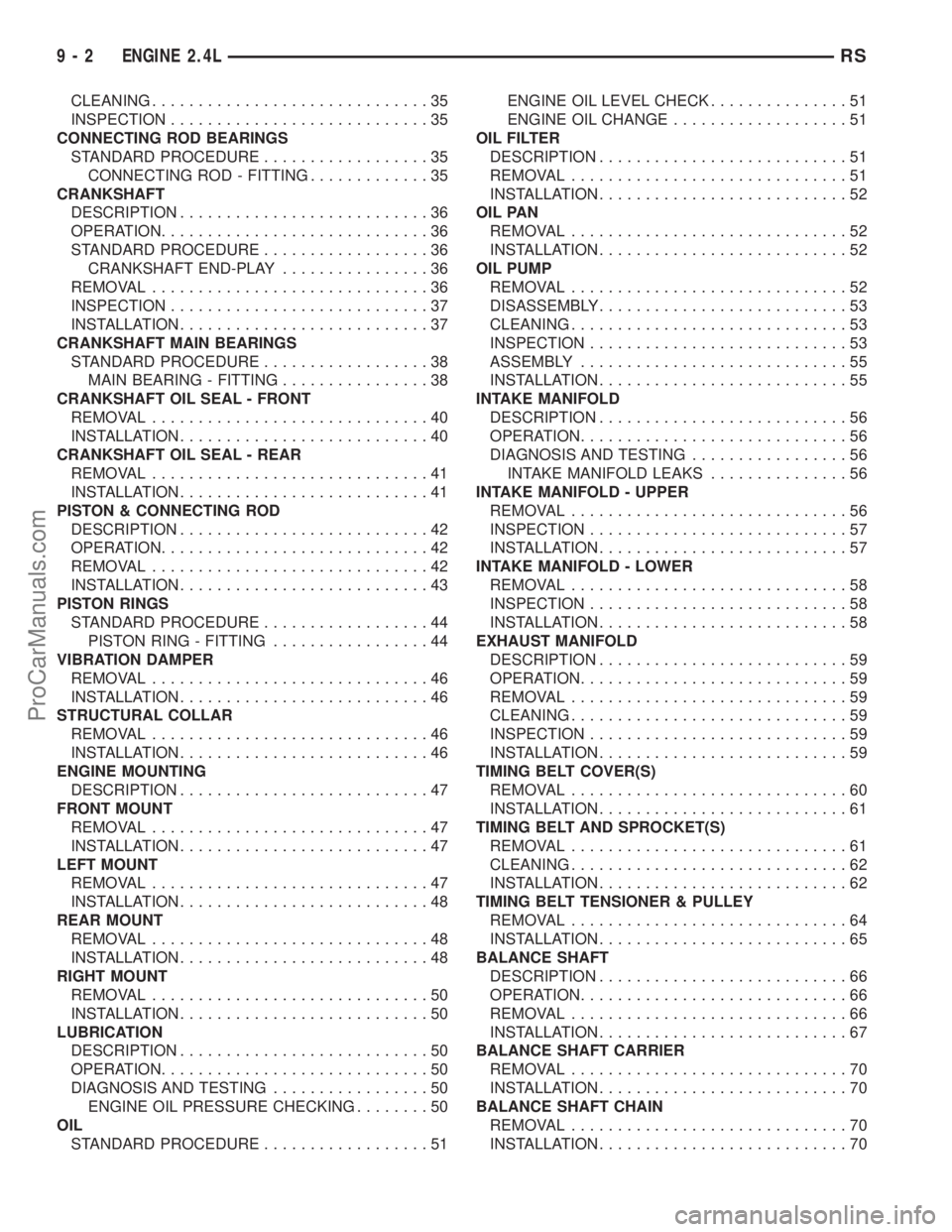
CLEANING..............................35
INSPECTION............................35
CONNECTING ROD BEARINGS
STANDARD PROCEDURE..................35
CONNECTING ROD - FITTING.............35
CRANKSHAFT
DESCRIPTION...........................36
OPERATION.............................36
STANDARD PROCEDURE..................36
CRANKSHAFT END-PLAY................36
REMOVAL..............................36
INSPECTION............................37
INSTALLATION...........................37
CRANKSHAFT MAIN BEARINGS
STANDARD PROCEDURE..................38
MAIN BEARING - FITTING................38
CRANKSHAFT OIL SEAL - FRONT
REMOVAL..............................40
INSTALLATION...........................40
CRANKSHAFT OIL SEAL - REAR
REMOVAL..............................41
INSTALLATION...........................41
PISTON & CONNECTING ROD
DESCRIPTION...........................42
OPERATION.............................42
REMOVAL..............................42
INSTALLATION...........................43
PISTON RINGS
STANDARD PROCEDURE..................44
PISTON RING - FITTING.................44
VIBRATION DAMPER
REMOVAL..............................46
INSTALLATION...........................46
STRUCTURAL COLLAR
REMOVAL..............................46
INSTALLATION...........................46
ENGINE MOUNTING
DESCRIPTION...........................47
FRONT MOUNT
REMOVAL..............................47
INSTALLATION...........................47
LEFT MOUNT
REMOVAL..............................47
INSTALLATION...........................48
REAR MOUNT
REMOVAL..............................48
INSTALLATION...........................48
RIGHT MOUNT
REMOVAL..............................50
INSTALLATION...........................50
LUBRICATION
DESCRIPTION...........................50
OPERATION.............................50
DIAGNOSIS AND TESTING.................50
ENGINE OIL PRESSURE CHECKING........50
OIL
STANDARD PROCEDURE..................51ENGINE OIL LEVEL CHECK...............51
ENGINE OIL CHANGE...................51
OIL FILTER
DESCRIPTION...........................51
REMOVAL..............................51
INSTALLATION...........................52
OIL PAN
REMOVAL..............................52
INSTALLATION...........................52
OIL PUMP
REMOVAL..............................52
DISASSEMBLY...........................53
CLEANING..............................53
INSPECTION............................53
ASSEMBLY.............................55
INSTALLATION...........................55
INTAKE MANIFOLD
DESCRIPTION...........................56
OPERATION.............................56
DIAGNOSIS AND TESTING.................56
INTAKE MANIFOLD LEAKS...............56
INTAKE MANIFOLD - UPPER
REMOVAL..............................56
INSPECTION............................57
INSTALLATION...........................57
INTAKE MANIFOLD - LOWER
REMOVAL..............................58
INSPECTION............................58
INSTALLATION...........................58
EXHAUST MANIFOLD
DESCRIPTION...........................59
OPERATION.............................59
REMOVAL..............................59
CLEANING..............................59
INSPECTION............................59
INSTALLATION...........................59
TIMING BELT COVER(S)
REMOVAL..............................60
INSTALLATION...........................61
TIMING BELT AND SPROCKET(S)
REMOVAL..............................61
CLEANING..............................62
INSTALLATION...........................62
TIMING BELT TENSIONER & PULLEY
REMOVAL..............................64
INSTALLATION...........................65
BALANCE SHAFT
DESCRIPTION...........................66
OPERATION.............................66
REMOVAL..............................66
INSTALLATION...........................67
BALANCE SHAFT CARRIER
REMOVAL..............................70
INSTALLATION...........................70
BALANCE SHAFT CHAIN
REMOVAL..............................70
INSTALLATION...........................70
9 - 2 ENGINE 2.4LRS
ProCarManuals.com
Page 1160 of 2321
ENGINE 2.4L
DESCRIPTION
The 2.4 Liter (148 cu. in.) in-line four cylinder
engine is a double over head camshaft with hydraulic
lifters and four valve per cylinder design. The engine
is free-wheeling; meaning it has provisions for piston-
to-valve clearance. However valve-to-valve interfer-
ence can occur, if camshafts are rotated
independently.
The cylinders are numbered from front of the
engine to the rear. The firing order is 1±3±4±2.
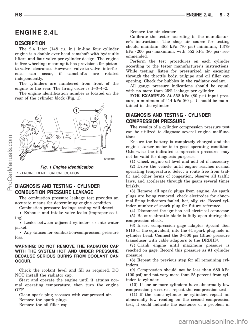
The engine identification number is located on the
rear of the cylinder block (Fig. 1).
DIAGNOSIS AND TESTING - CYLINDER
COMBUSTION PRESSURE LEAKAGE
The combustion pressure leakage test provides an
accurate means for determining engine condition.
Combustion pressure leakage testing will detect:
²Exhaust and intake valve leaks (improper seat-
ing).
²Leaks between adjacent cylinders or into water
jacket.
²Any causes for combustion/compression pressure
loss.
WARNING: DO NOT REMOVE THE RADIATOR CAP
WITH THE SYSTEM HOT AND UNDER PRESSURE
BECAUSE SERIOUS BURNS FROM COOLANT CAN
OCCUR.
Check the coolant level and fill as required. DO
NOT install the radiator cap.
Start and operate the engine until it attains nor-
mal operating temperature, then turn the engine
OFF.
Clean spark plug recesses with compressed air.
Remove the spark plugs.
Remove the oil filler cap.Remove the air cleaner.
Calibrate the tester according to the manufactur-
er's instructions. The shop air source for testing
should maintain 483 kPa (70 psi) minimum, 1,379
kPa (200 psi) maximum, with 552 kPa (80 psi) rec-
ommended.
Perform the test procedures on each cylinder
according to the tester manufacturer's instructions.
While testing, listen for pressurized air escaping
through the throttle body, tailpipe and oil filler cap
opening. Check for bubbles in the radiator coolant.
All gauge pressure indications should be equal,
with no more than 25% leakage per cylinder.
FOR EXAMPLE:At 552 kPa (80 psi) input pres-
sure, a minimum of 414 kPa (60 psi) should be main-
tained in the cylinder.
DIAGNOSIS AND TESTING - CYLINDER
COMPRESSION PRESSURE
The results of a cylinder compression pressure test
can be utilized to diagnose several engine malfunc-
tions.
Ensure the battery is completely charged and the
engine starter motor is in good operating condition.
Otherwise the indicated compression pressures may
not be valid for diagnosis purposes.
(1) Check engine oil level and add oil if necessary.
(2) Drive the vehicle until engine reaches normal
operating temperature. Select a route free from traf-
fic and other forms of congestion, observe all traffic
laws, and accelerate through the gears several times
briskly.
(3) Remove all spark plugs from engine. As spark
plugs are being removed, check electrodes for abnor-
mal firing indicators fouled, hot, oily, etc. Record cyl-
inder number of spark plug for future reference.
(4) Disconnect the ignition coil electrical connector.
(5) Be sure throttle blade is fully open during the
compression check.
(6) Insert compression gage adaptor Special Tool
8116 or the equivalent, into the #1 spark plug hole in
cylinder head. Connect the 0±500 psi (Blue) pressure
transducer with cable adaptors to the DRBIIIt.
(7) Crank engine until maximum pressure is
reached on gage. Record this pressure as #1 cylinder
pressure.
(8) Repeat the previous step for all remaining cyl-
inders.
(9) Compression should not be less than 689 kPa
(100 psi) and not vary more than 25 percent from cyl-
inder to cylinder.
(10) If one or more cylinders have abnormally low
compression pressures, repeat the compression test.
(11) If the same cylinder or cylinders repeat an
abnormally low reading on the second compression
test, it could indicate the existence of a problem in
Fig. 1 Engine Identification
1 - ENGINE IDENTIFICATION LOCATION
RSENGINE 2.4L9-3
ProCarManuals.com
Page 1164 of 2321
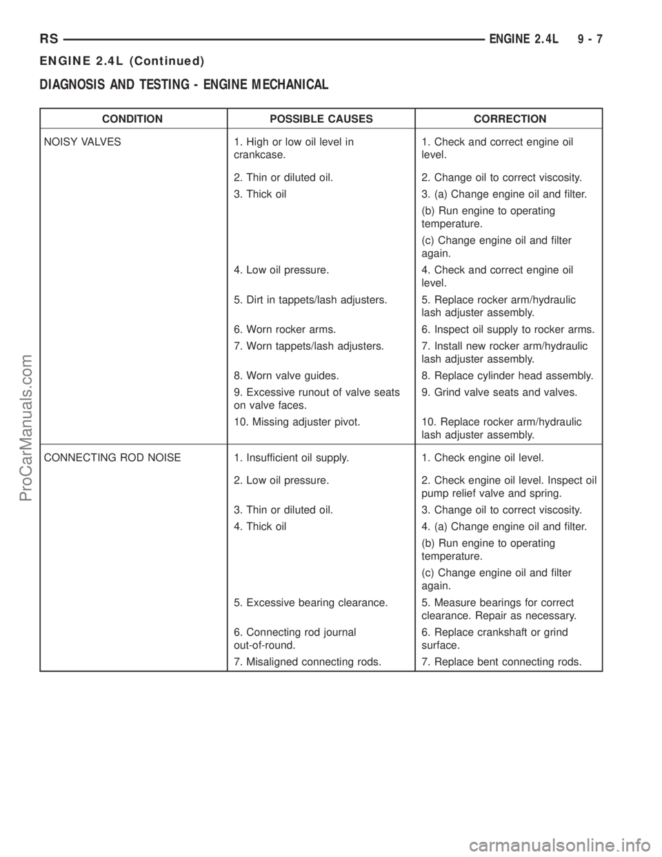
DIAGNOSIS AND TESTING - ENGINE MECHANICAL
CONDITION POSSIBLE CAUSES CORRECTION
NOISY VALVES 1. High or low oil level in
crankcase.1. Check and correct engine oil
level.
2. Thin or diluted oil. 2. Change oil to correct viscosity.
3. Thick oil 3. (a) Change engine oil and filter.
(b) Run engine to operating
temperature.
(c) Change engine oil and filter
again.
4. Low oil pressure. 4. Check and correct engine oil
level.
5. Dirt in tappets/lash adjusters. 5. Replace rocker arm/hydraulic
lash adjuster assembly.
6. Worn rocker arms. 6. Inspect oil supply to rocker arms.
7. Worn tappets/lash adjusters. 7. Install new rocker arm/hydraulic
lash adjuster assembly.
8. Worn valve guides. 8. Replace cylinder head assembly.
9. Excessive runout of valve seats
on valve faces.9. Grind valve seats and valves.
10. Missing adjuster pivot. 10. Replace rocker arm/hydraulic
lash adjuster assembly.
CONNECTING ROD NOISE 1. Insufficient oil supply. 1. Check engine oil level.
2. Low oil pressure. 2. Check engine oil level. Inspect oil
pump relief valve and spring.
3. Thin or diluted oil. 3. Change oil to correct viscosity.
4. Thick oil 4. (a) Change engine oil and filter.
(b) Run engine to operating
temperature.
(c) Change engine oil and filter
again.
5. Excessive bearing clearance. 5. Measure bearings for correct
clearance. Repair as necessary.
6. Connecting rod journal
out-of-round.6. Replace crankshaft or grind
surface.
7. Misaligned connecting rods. 7. Replace bent connecting rods.
RSENGINE 2.4L9-7
ENGINE 2.4L (Continued)
ProCarManuals.com
Page 1165 of 2321
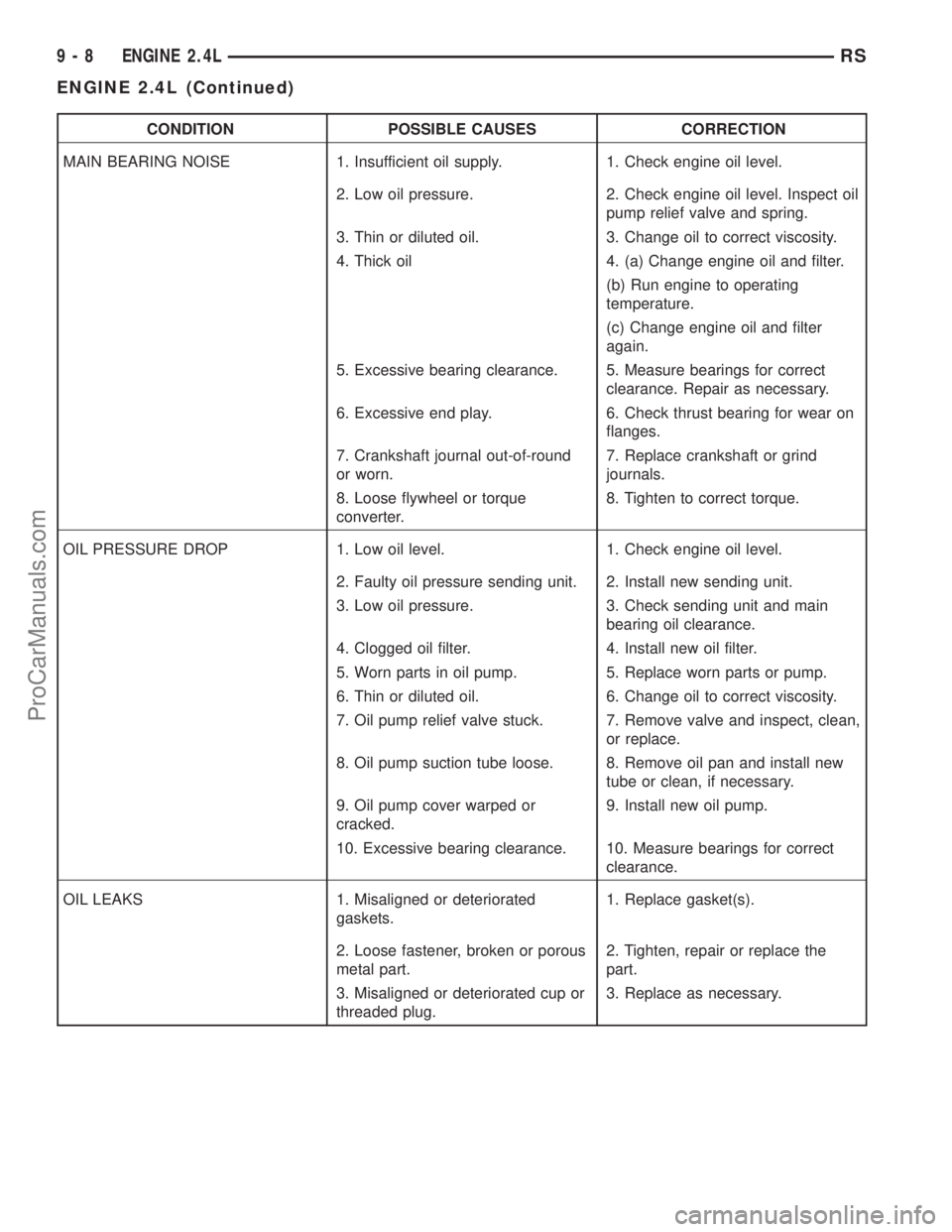
CONDITION POSSIBLE CAUSES CORRECTION
MAIN BEARING NOISE 1. Insufficient oil supply. 1. Check engine oil level.
2. Low oil pressure. 2. Check engine oil level. Inspect oil
pump relief valve and spring.
3. Thin or diluted oil. 3. Change oil to correct viscosity.
4. Thick oil 4. (a) Change engine oil and filter.
(b) Run engine to operating
temperature.
(c) Change engine oil and filter
again.
5. Excessive bearing clearance. 5. Measure bearings for correct
clearance. Repair as necessary.
6. Excessive end play. 6. Check thrust bearing for wear on
flanges.
7. Crankshaft journal out-of-round
or worn.7. Replace crankshaft or grind
journals.
8. Loose flywheel or torque
converter.8. Tighten to correct torque.
OIL PRESSURE DROP 1. Low oil level. 1. Check engine oil level.
2. Faulty oil pressure sending unit. 2. Install new sending unit.
3. Low oil pressure. 3. Check sending unit and main
bearing oil clearance.
4. Clogged oil filter. 4. Install new oil filter.
5. Worn parts in oil pump. 5. Replace worn parts or pump.
6. Thin or diluted oil. 6. Change oil to correct viscosity.
7. Oil pump relief valve stuck. 7. Remove valve and inspect, clean,
or replace.
8. Oil pump suction tube loose. 8. Remove oil pan and install new
tube or clean, if necessary.
9. Oil pump cover warped or
cracked.9. Install new oil pump.
10. Excessive bearing clearance. 10. Measure bearings for correct
clearance.
OIL LEAKS 1. Misaligned or deteriorated
gaskets.1. Replace gasket(s).
2. Loose fastener, broken or porous
metal part.2. Tighten, repair or replace the
part.
3. Misaligned or deteriorated cup or
threaded plug.3. Replace as necessary.
9 - 8 ENGINE 2.4LRS
ENGINE 2.4L (Continued)
ProCarManuals.com